ASSIGNMENT
Group
- Compare the performance and development workflows for othe architectures.
Individual
- Program your board to do something.
TOOLS and SOFTWARE
Arduino IDE
Microcontroller Datasheet
The first part of this week was to go through a microcontroller's datasheet. Since I'm going to use my "Hello World" board which I designed during the week of Electronic design and has the ATTiny44 microcontroller, I'm going to go through the this datasheet of ATTiny44.
Datasheets are basically a summary (a pretty huge one) of the component and it includes all the information related to the performance, specifications and other technical details. Now, reading the whole datasheet can be overwhelming because it is usually very long and can be difficult to read specially for beginners so it is good to know the most important pieces of information needed.
During my university years, I went through my fair share of datasheets and I can say that the most common information I was looking for are:
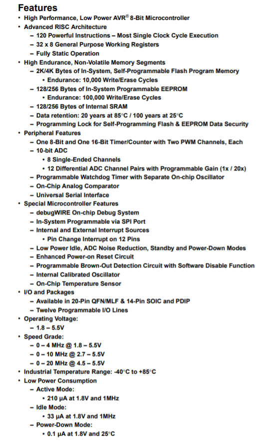
- - Component Features which are usually located in the first few pages of a datasheet. These features can be considered like a summary which can help you identify if the component is right for your application.
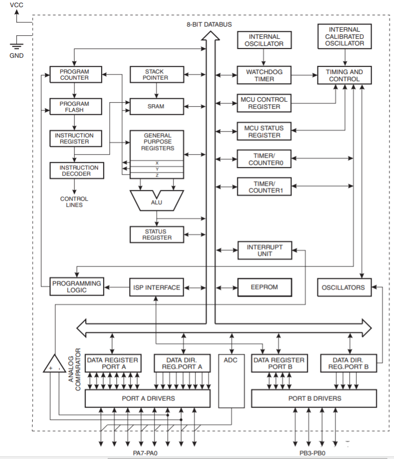
- - Component Block Diagram which explains how the different internal systems inside the component work.
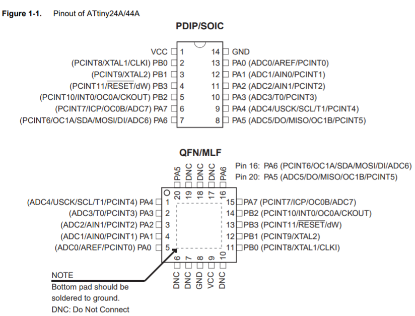
- - The Pinout schematic which helps in identifying the functions of the different pins and where they're located.
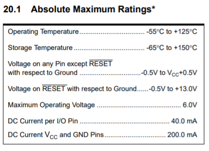
- - Absolute Maximum Ratings which are part of the electrical characteristics that contain the values of the maximum ratings such as voltage a component can withstand before it gets damaged.
There after going through the ATTiny44 datasheet, here are the main information I gathered:
Microcontroller Features
Microcontroller Block Diagram
Microcontroller Pinout
Absolute Maximum Ratings
Programming Using Arduino IDE
As I mentioned previously, I'm going to use my "Hello World" board which I designed during the week of Electronic design (Week 7) to do this assignment.
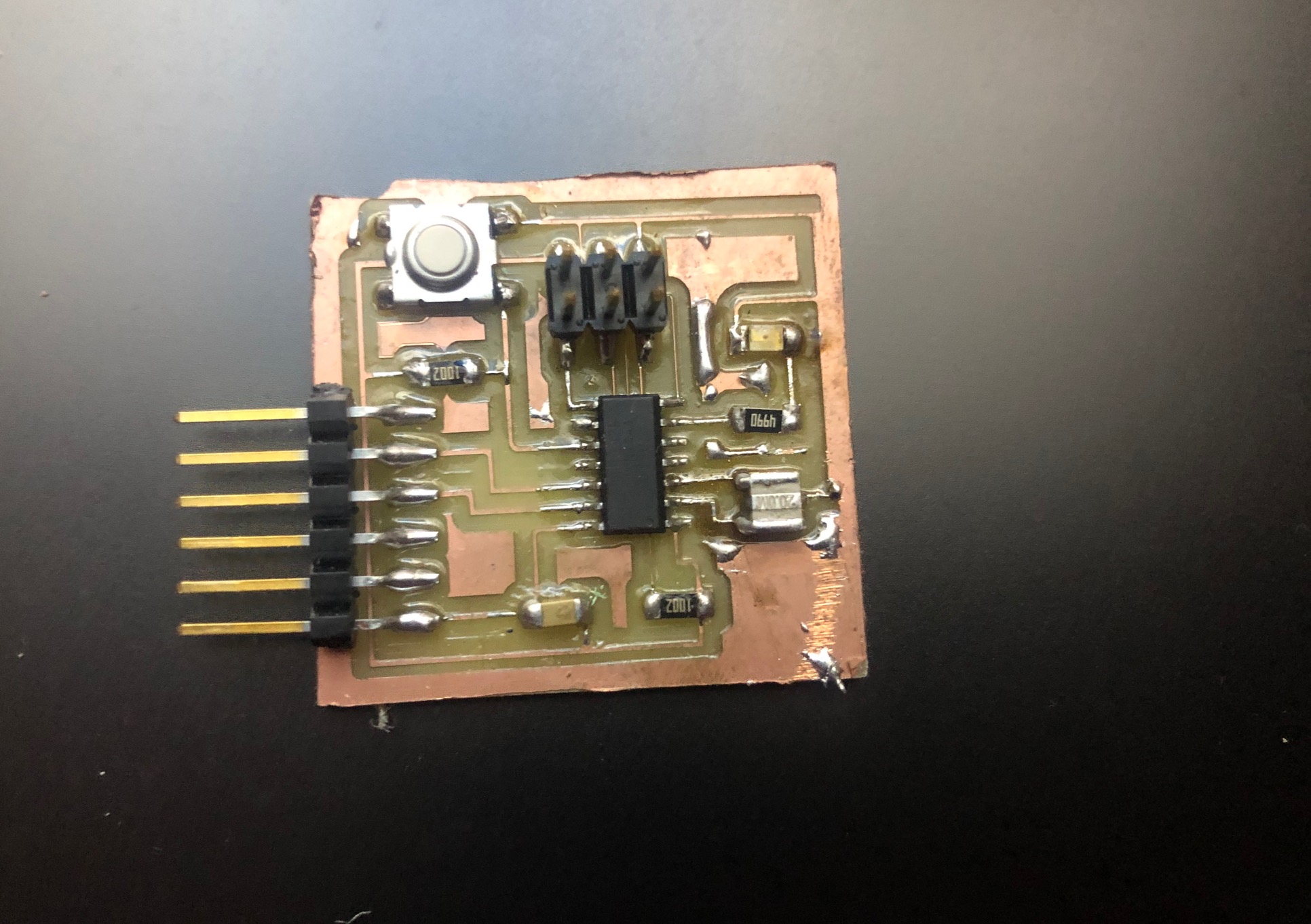
1- To program this board, I used the FABISP as my programmer. I opened Arduio IDE and opened the 'Button' example code
.png)
2- I connected FABISP with Hello World using the MOSI, MISO, SCK, RESET, VCC and GND headers.
3- I modified the code according to where the LED and button are connected in my board
.png)
4- I modified the settings in Arduino IDE according to my board and the port I'm connecting it in
5- Then I uploaded the code and Burn bootloader the Atiny chip in my Hello world board.
.png)
Finally, the code was working fine on the hello world board