Schematic Design

The first thing to do for this assignment is to analyze the schematic for the Joystick module to know exactly how it is going to be connected to the microcontroller.


The above image is the internal diagram of a Joystick Module. It consists of two Potentiometer, each for one axis (X and Y). Both 10k potentiometer are independent to move in their particular direction. SW (Switch) pin is connected to a push button internally.

Joystick Module can be used with Arduino, Raspberry Pi and any other Micro-controllers. We just have to connect the axis Pins VRx and VRy to the ADC Pins of the micro-controller. And if we want to use the switch then we should connect it to the digital Pin of the Micro-controller.


The interfacing diagram of Joystick Module with the Arduino is shown below. This diagram helps to connect the joystick Module with Arduino and get the analog output based on the direction of movement of Joystick Knob.


After Interfacing Joystick Module with the Arduino, we will get the analog output. The output range is fixed for each direction. The below image shows, the value of analog output for X and Y axis based on the movement of Joystick Module in all four directions (+X, -X, +Y, -Y). Based on this we will also get some analog value when moving the knob diagonally.


To test the joystick I used commercial arduino board to test my connection and the output results from the Joystick module as an input device, before designing and fabricating your own PCB board. The code was the following:

                
// Arduino pin numbers const int SW_pin = 2; // digital pin connected to switch output const int X_pin = 0; // analog pin connected to X output const int Y_pin = 1; // analog pin connected to Y output void setup() { pinMode(SW_pin, INPUT); digitalWrite(SW_pin, HIGH); Serial.begin(115200); } void loop() { Serial.print("Switch: "); Serial.print(digitalRead(SW_pin)); Serial.print("\n"); Serial.print("X-axis: "); Serial.print(analogRead(X_pin)); Serial.print("\n"); Serial.print("Y-axis: "); Serial.println(analogRead(Y_pin)); Serial.print("\n\n"); delay(500); }

Running the code will give us the following results:

        1.     Moving the Joystick to +x direction.

        2.     Moving the Joystick to -x direction.

        3.     Moving the Joystick to +y direction.

        4.     Moving the Joystick to -y direction.


After making sure that the Joystick module is working perfectly with the arduino commercial board, it is know time to design my own fabduino using eagle software.

To design my Fabaduino I decided to use the Atmega328-P microcontroller that has the following schematic diagram:


Since I did not have the library for the Atmega328-P microcontroller, I had to download it from Adafruit-Eagle-Library-master and I added the library from the library manager in Eagle.

After adding the library, the component can be found under Adafruit -> ATMEGA168*P -> ATMEGA168-20P. You will notice, it is not exactly the Atmega328, but the Atmega168 has the exact same package type and pinout so they can be used interchangeably for Eagle design purposes.


Then after that I started to add components, like crystal oscilator because Atmega328-P crystals are used to help when the microconroller is dealing with time issues, for example if we build a project that turns a switch A OFF after 15 minutes ON and turn ON switch B, C & D one after another with a 20 minutes step. We can use Arduino software to program the chip to do that, but how Atmega328-P calculate the time is by using this crystal, the number on the top of the crystal is 16.000H9H this gives us information about the frequency which is 16,000,000 Hertz or 16 Mhz, this small component can make 16 millions cycles per second so using this concept Arduino can calculate time. The crystal is used along with two capacitor of 22pF value, and connected to pin PB6 and PB7 in the atmega328-p.


Then I connected a pull up resistor, and switch button with the reset pin of atmega328-p, this is important to be able to program the board.


After that I created the pins I require for my connections, like the joystick pins, programming pins, and power supply pin. Also I added pins for NRF24L01 module, which is something I am going to use in the future for my final project.


I also added two voltage regulators, one to regulate the 9V to 5V to supply the entire circuit, and the other one is to regulate 5V to 3.3V to supply the NRF24L01 module.


Finally I added LED connected to VCC to indicate when the circuit is supplied by voltage.


After I checked that my connections are all fine I started doing the routing for the PCB.


After around one hour of trying I was able to finish the routing of the circuit and it is know ready to be fabricated and programmed.


Circuit Fabrication

Before Fabricating the circuit, we should first put it in FabModules to prepare the files for the milling process. With that being said, I first prepared the traces milling file as shown below:


The drilling file:


And finally the outline file:


The components and the fabricated PCB of the input device is the following:


Testing

The final testing of the input device worked perfectly with the fabricated PCB:


Schematic Design

Before working with stepper motor it is important to understand how it works and how to operate it. A stepper motor is a brushless, synchronous electric motor that converts digital pulses into mechanical shaft rotation. Its normal shaft motion consists of discrete angular movements of essentially uniform magnitude when driven from sequentially switched DC power supply.

Every revolution of the stepper motor is divided into a discrete number of steps, in many cases 200 steps, and the motor must be sent a separate pulse for each step. The stepper motor can only take one step at a time and each step is the same size.


To control stepper motor with arduino or any microcontroller we should first connect it to a motor driver. The micro-controller has it’s operating voltage limit, say 3.3V or 5V and many stepper motors works at higher voltages than that, therefore, it is important to have a driver to control switching of stepper motor voltages.

Driver is nothing but a circuit arranged to make switching simple and “secure”. The voltage rating of stepper driver is more than micro-controller. So you can easily control the stepper motor of given voltage rating using driver of that rating


As driver I am going to use the L298N module. This driver has two H-Bridges, each H-Bridge will drive one of the electromagnetic coils of a stepper motor. By energizing these electromagnetic coils in a specific sequence, the shaft of a stepper can be moved forward or backward precisely in small steps. However, the speed of a motor is determined by the how frequently these coils are energized.


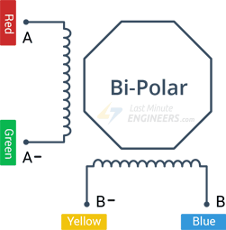
The stepper motor I am using is NEMA 17 bipolar stepper rated at 12V. It offers 200 steps per revolution, and can operate at at 60 RPM. Before start hooking the motor up with the module, it is important to determine the A+, A-, B+ and B- wires on the motor. The best way to do this is to check the datasheet of the motor, or check the color code used with the motor.


The connections of the stepper motor to the driver and arduino is simple, first I connected external 12V power supply to the VCC terminal. It is also very important to keep both the ENA & ENB jumpers in place so the the motor is always enabled. Then connect the input pins(IN1, IN2, IN3 and IN4) of the L298N module to four Arduino digital output pins(e.g. 8, 9, 10 and 11). Finally, connect the A+, A-, B+ and B- wires from the stepper motor to the module as shown in the illustration below.


It is very important to me to try these connections first using comercial arduino, to make sure everything is working before moving to designing the PCB.


The code to operate the stepper motor is very easy the only thing require before uploading the code into the arduino is to install the the library of the stepper motor. The following code is to operate the stepper motor in 200 steps, with 60 RPM speed.


// Include the Arduino Stepper Library #include <Stepper.h> // Number of steps per output rotation const int stepsPerRevolution = 200; // Create Instance of Stepper library Stepper myStepper(stepsPerRevolution, 8, 9, 10, 11); void setup() { // set the speed at 60 rpm: myStepper.setSpeed(60); // initialize the serial port: Serial.begin(9600); } void loop() { // step one revolution in one direction: Serial.println("clockwise"); myStepper.step(stepsPerRevolution); delay(500); // step one revolution in the other direction: Serial.println("counterclockwise"); myStepper.step(-stepsPerRevolution); delay(500); }

The following video shows how the stepper motor is working with comercial arduino.


After making sure that everything is working perfectly with comercial arduino, it is now time to design a PCB for my circuit. The microcontroller I am going to use for my cicuit is the Amega328-P, that has the following schematic:


For this assignment I had the schematic almost ready from the previous assignment "Input Devices". However, I just need to edit few pins and remove other to obtain the required PCB.

The previous schematic had the following:

        1.     Crystal oscilator circuit with two 22pF Capacitor.
        2.     Switch connected to the Reset with pull up resistor.
        3.     Programming pins.
        4.     Joystick pins that has two analog pins.
        5.     Power pins.
        6.     NRF24L01 module pins.
        7.     Voltage regulator to convert 9V to 5V.
        8.     Voltage regulator to convert 5V to 3.3V.
        9.     LED connected to power pin.

Things I am going to remove for this schematic is the Joystick pins connections and I am going to replace them with the stepper motor connection. The final schematic will look like the following:


Finally I was able to finish the routing of the circuit, and the final results looked like the following:


Circuit Fabrication

Before Fabricating the circuit, we should first put it in FabModules to prepare the files for the milling process. With that being said, I first prepared the traces milling file as shown below:


The drilling file:


And finally the outline file:


The components and the fabricated PCB of the output device is the following:


Testing

The final testing of the output device worked perfectly with the fabricated PCB: