8. Computer controlled machining
This week I have to build something big with a CNC, it has to use some joint.
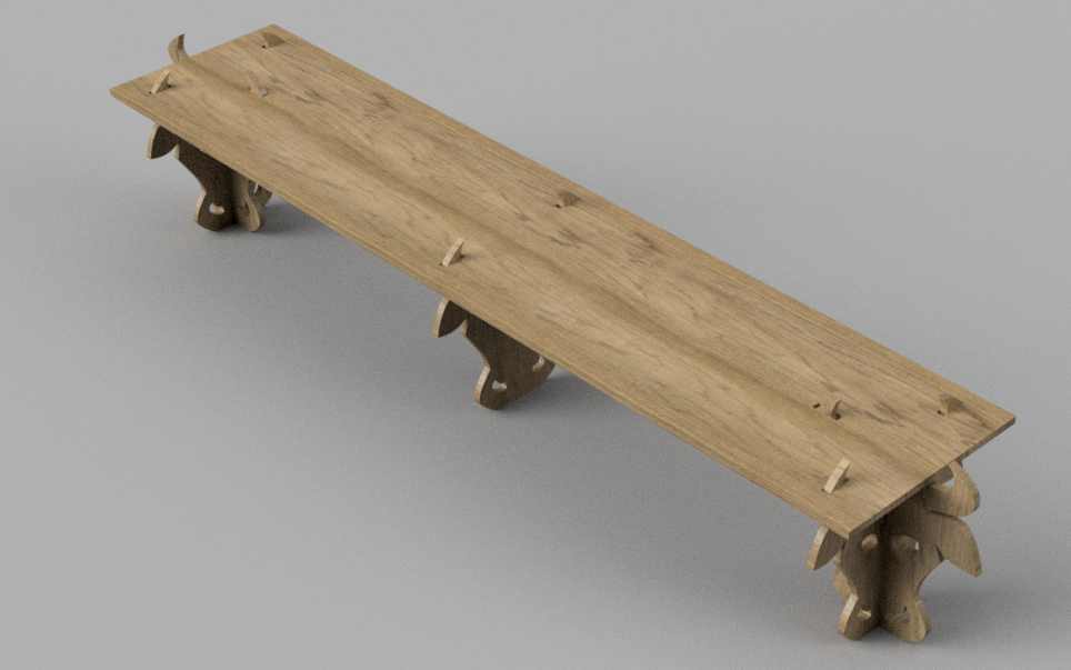
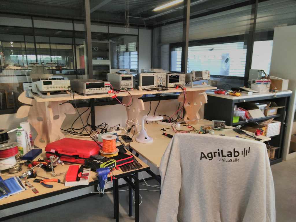
I need to improve my electronic bench, I decide to build a shelf dedicated for my oscilloscope, multimeter, signal generator and electric power. If you follow my previous weeks assignement, you’ll recognise the thematic of the cow.
Inkscape
I take back my inkscape design .
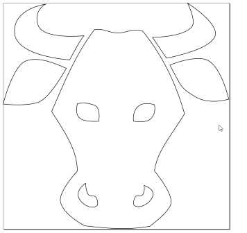
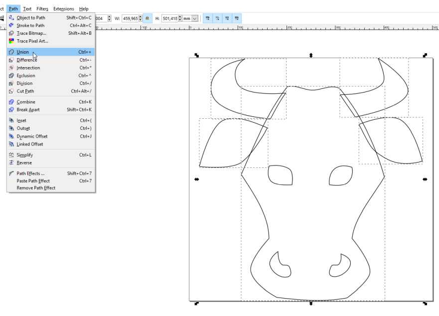
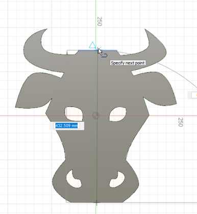
The design is made of several lines not connected. I want to have one piece with some holes for the eyes and the nose.
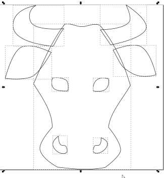
I simply displace those elements and make an union to form one solid piece.
Then I flatten the top of the head and the bottom of the face.
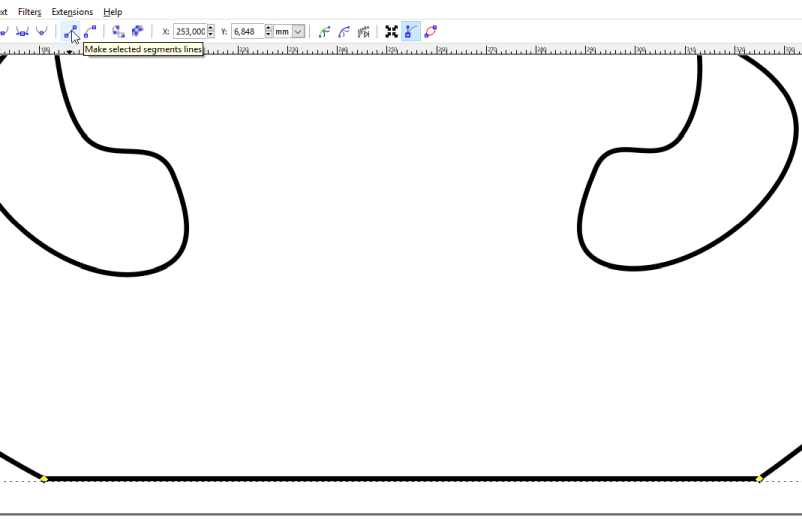
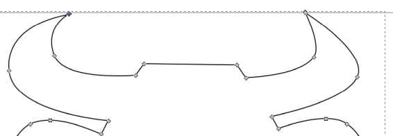
I need those flat lines : for the foot of the shelf and the top of the head to support the shelf. Then I saved the file in SVG to import it in Fusion360.
Fusion
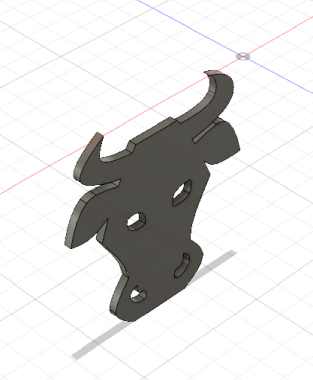
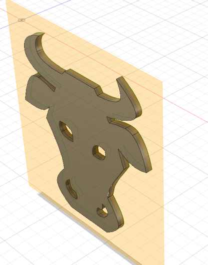
I import the file in a sketch in Fusion.
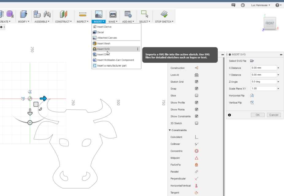
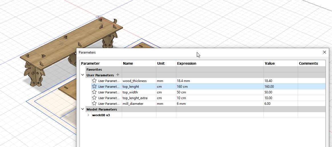
I extrude the face with a parametric valor of the thickness of the material , here 18.4 mm
I created a plane between the two face to create an axis in the middle of the object.
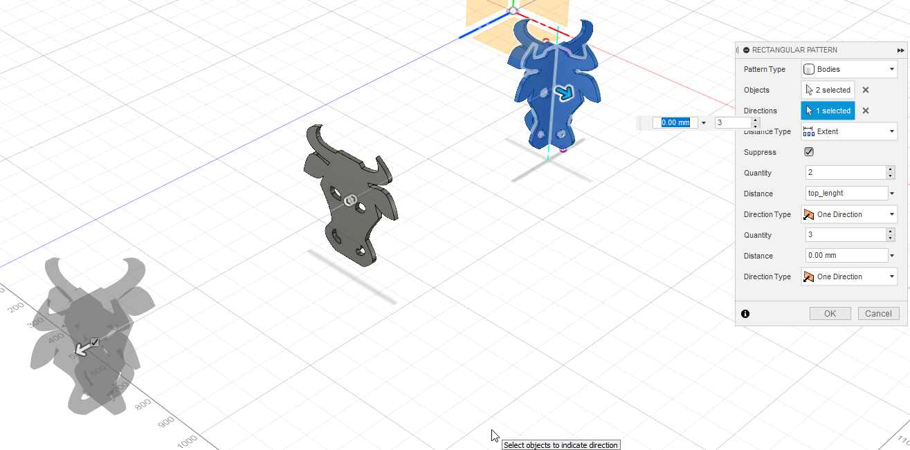
I duplicate the element with the linear pattern function with a parametric distance of half the lenght of the top shelf.
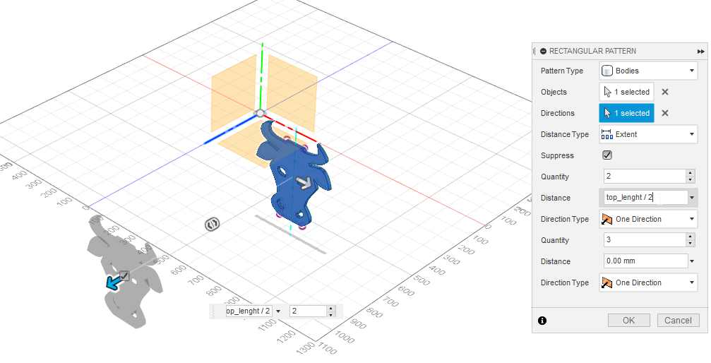
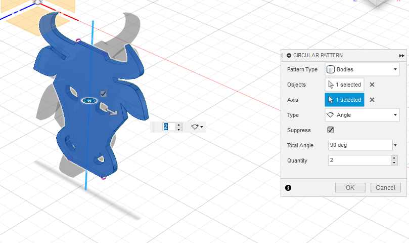
Then I make another copie with the circular pattern to have a stable foot for the shelf.
And copy again those two elements at a parametric distance of the lenght of the top shelf.
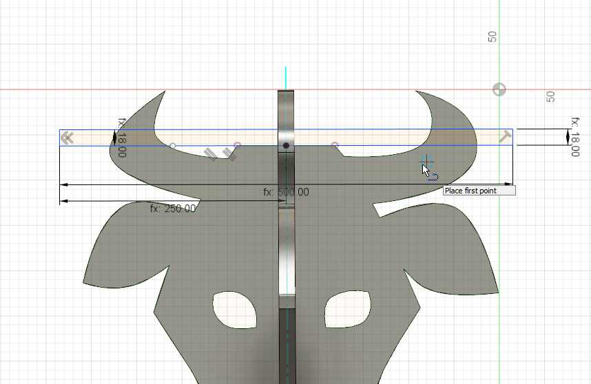
I design a sketch on the first face with several lines to create a rectangle. I start from the symmetry top point. All those lignes are parametric with the top shelf thikness and wideness.
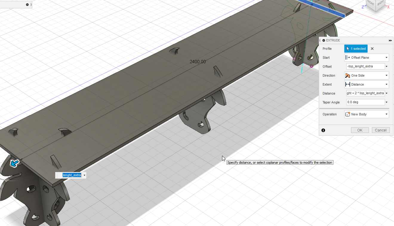
Then I extrude that rectangle with parametric values : the lenght of the top shelf and an extra lenght on both sides.
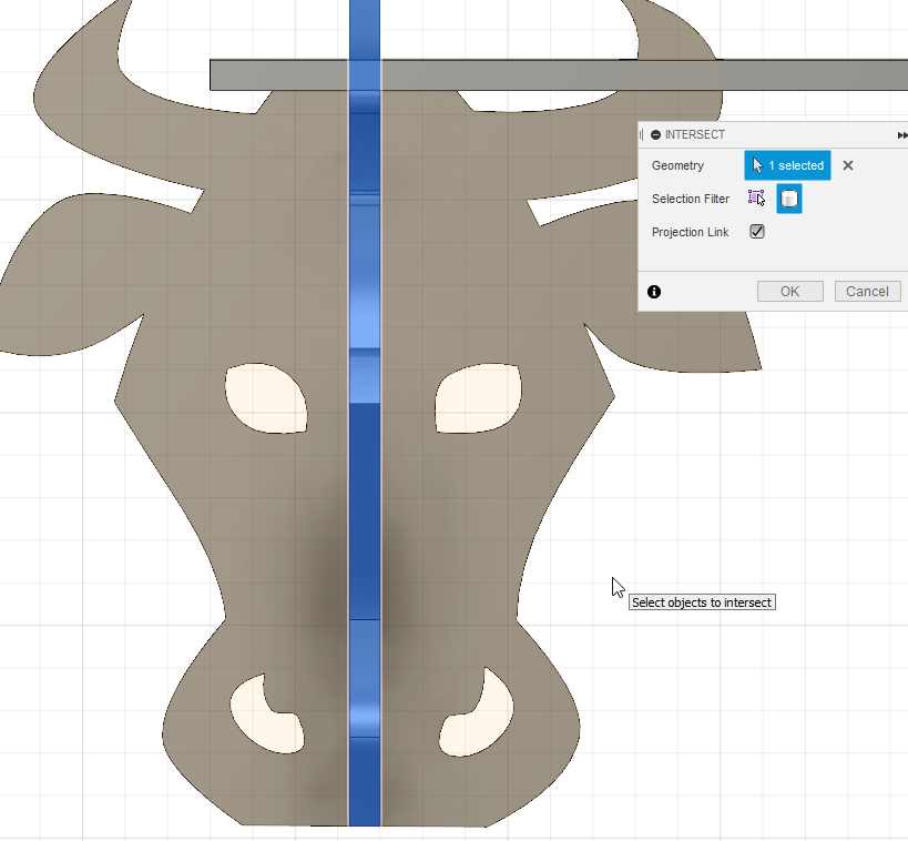
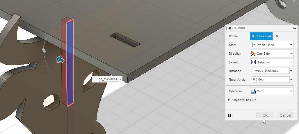
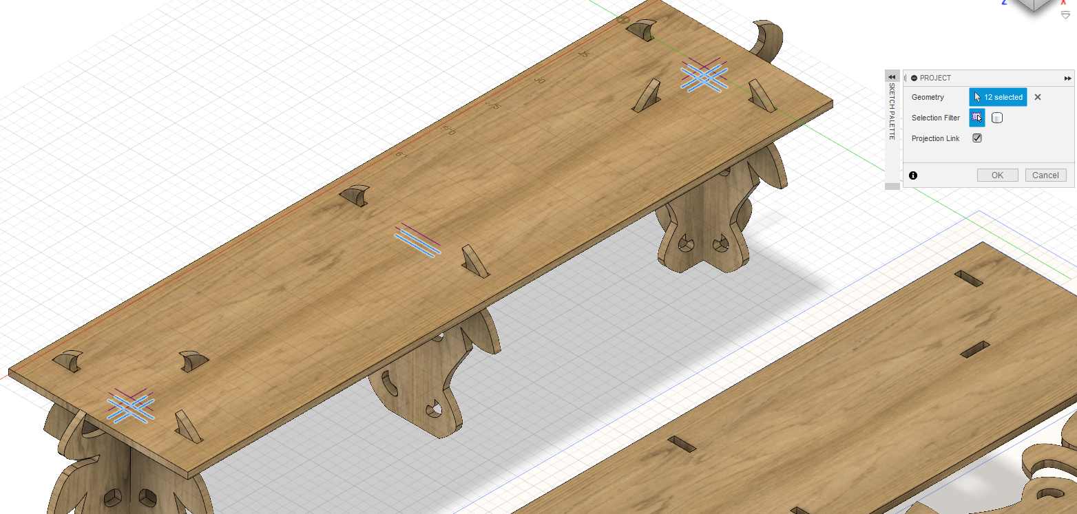
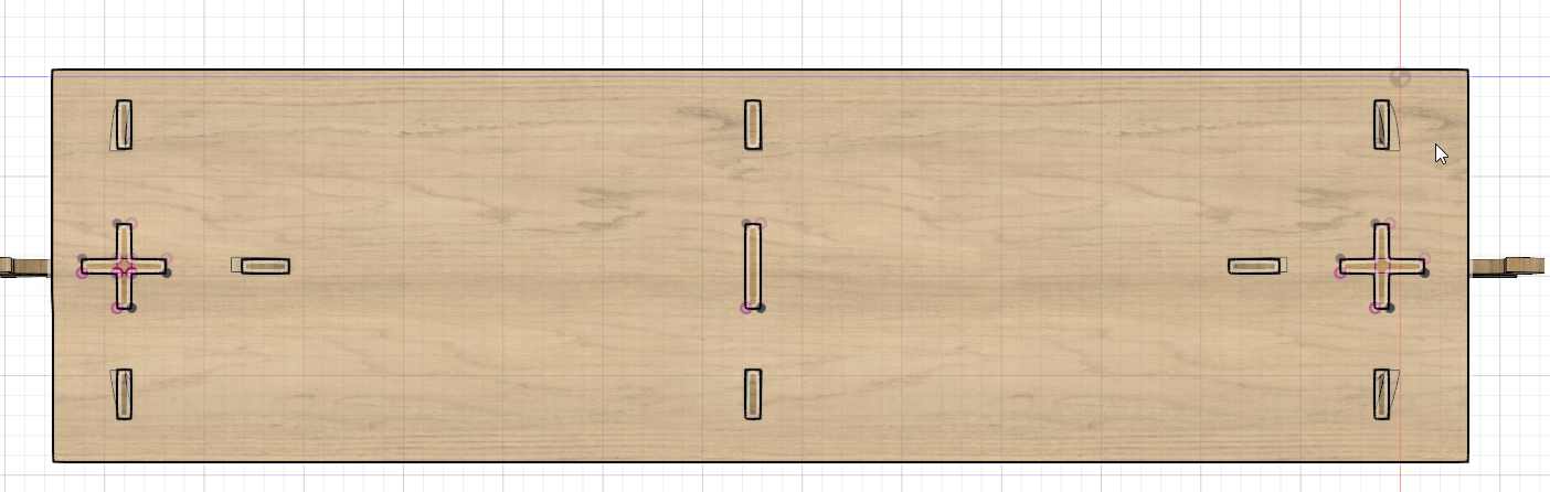
On the bottom side of the top shelf I made a projection of the intersection and draw the rectangles connecting those points.
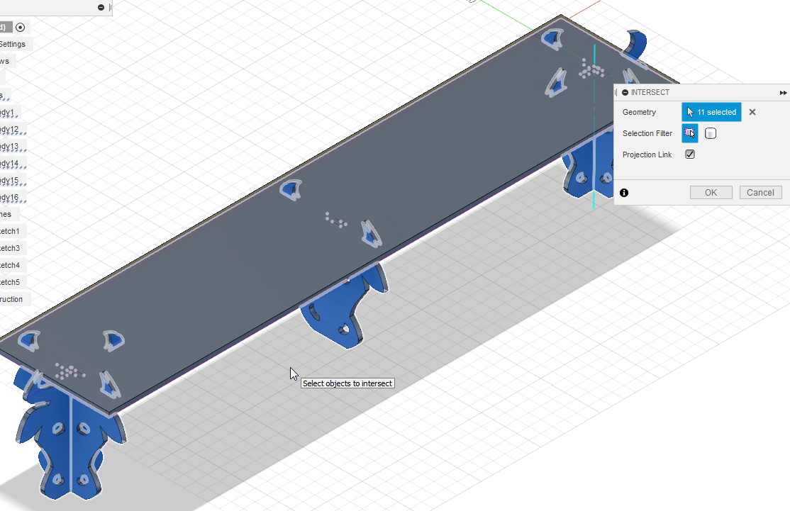
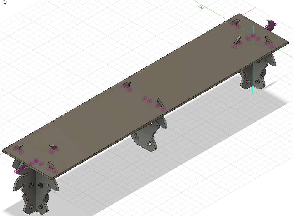
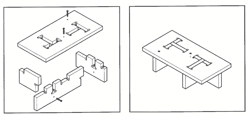
And “extrude a cut” of those rectangles. It will be the first join to connect the top shelf with the foot made of the cow head.
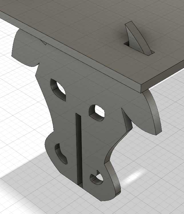
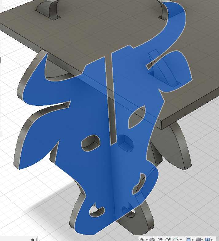
The foot needs to have some join, here a close-up of the side foots.
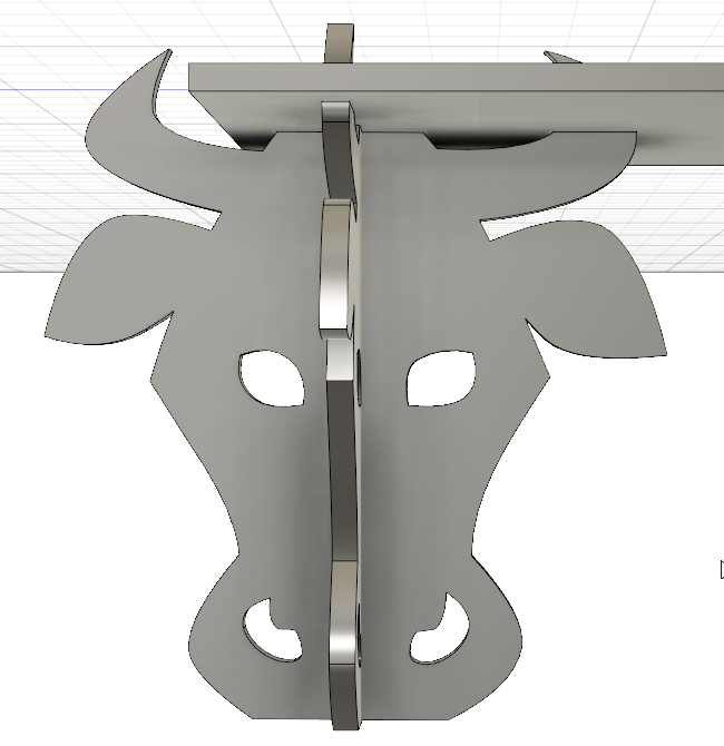
I create a projection of the perpendicular object on a skecth to draw the join and remove the volume.
For one piece I remove the upper half for the other the lower half.
It’s finished for the design.
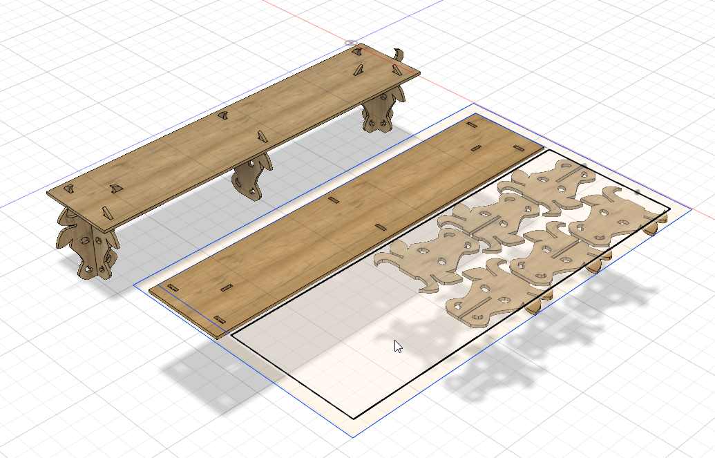
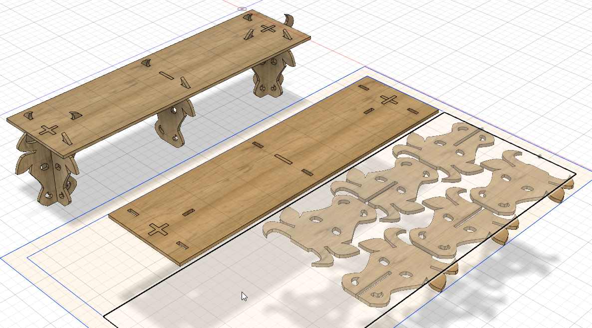
I prepare the file for the machining. I make a copy of all the elements and lay them flat on a flat pannel (the dimension of my wood sheet).
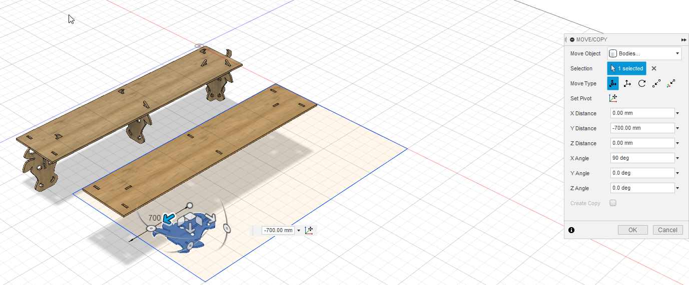
And I optimized the placement. I don’t use a nesting software, I place the element in a smart way.
I measure and adjust all the parameter of the shelf.
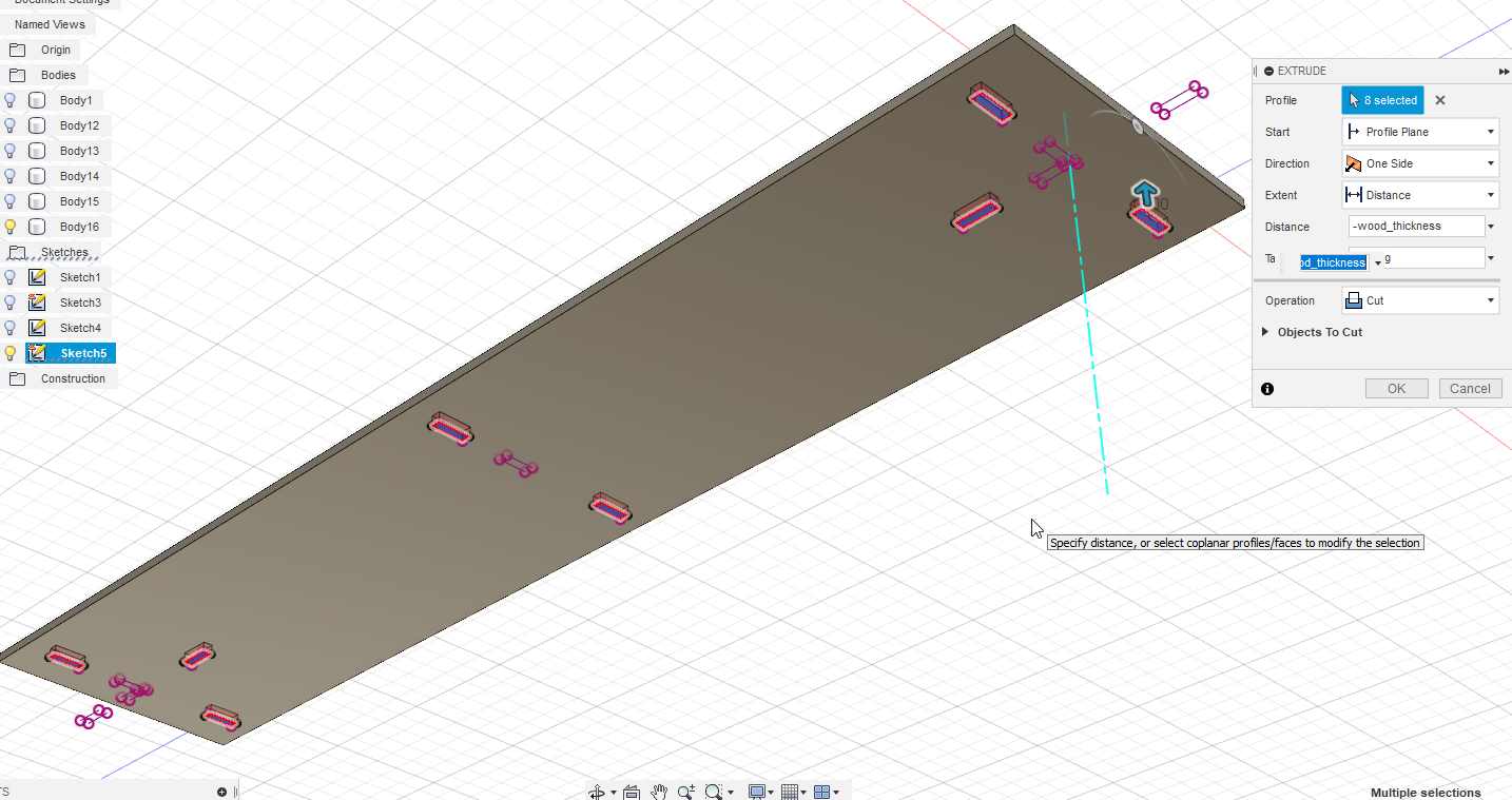
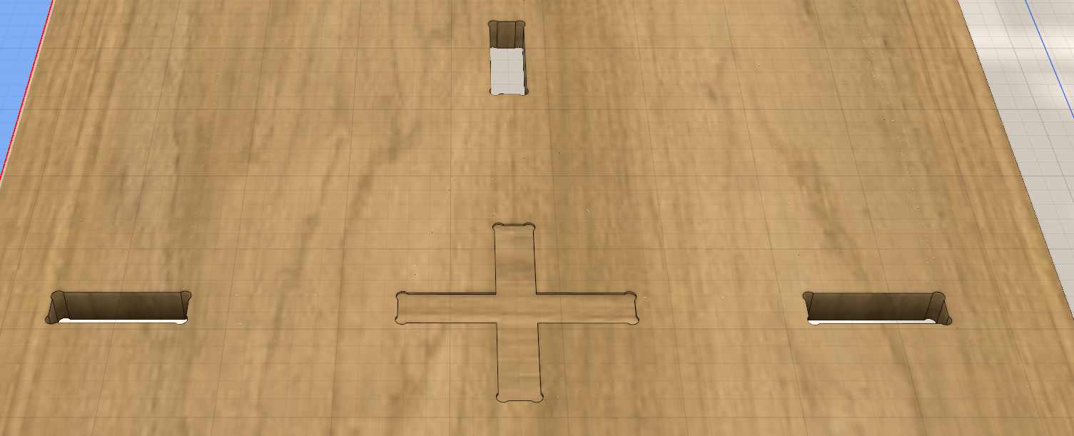
Finally I decide to create some pocket on the top side of the shelf, it’s just in case I need to drill some screws, they’ll be perfectly align with the bottoms parts. I create a projection and cut those volumes.
The result before my last step.
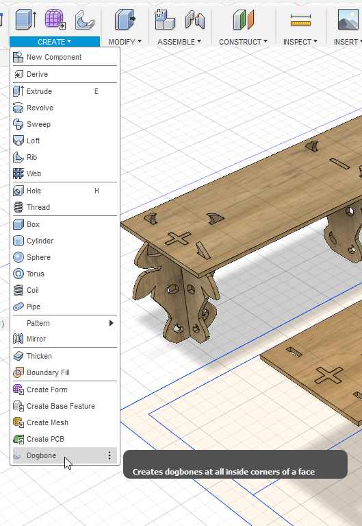
Dogbone
I install a dogbone plugin from https://github.com/caseycrogers/Dogbone .
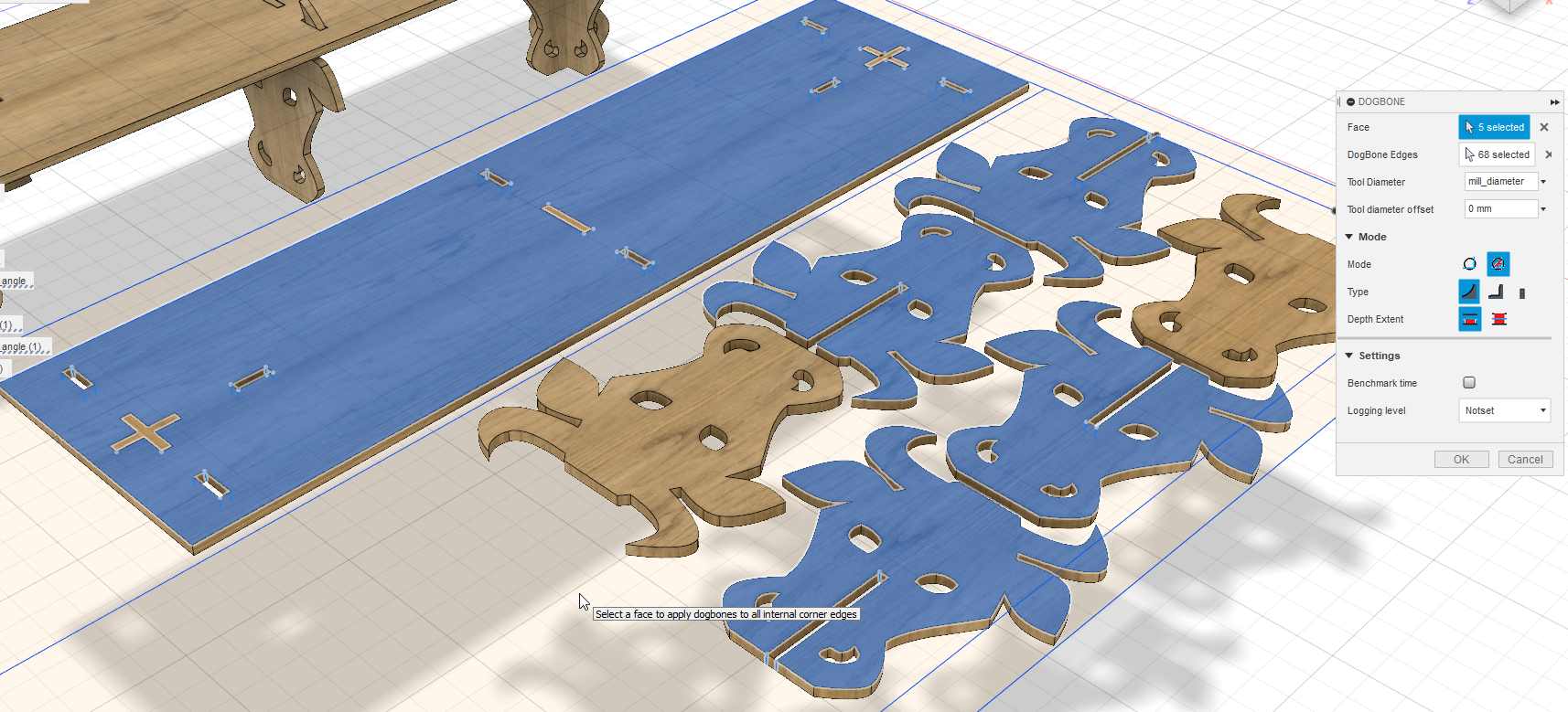
I select the elements and you can see in all the inside corner a litlle blue circle. I put a parametric value of the drill size, here 6 mm.
CAM - Fusion Manufacture
I switch to the CAM module of fusion now called Manufacture.
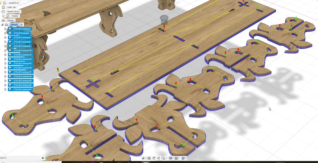
I make the setup and select all the elements I want to mill.
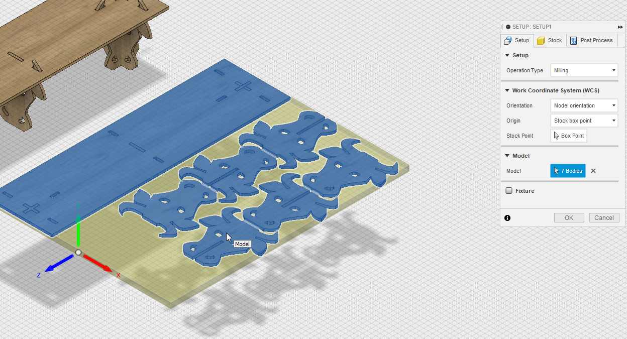
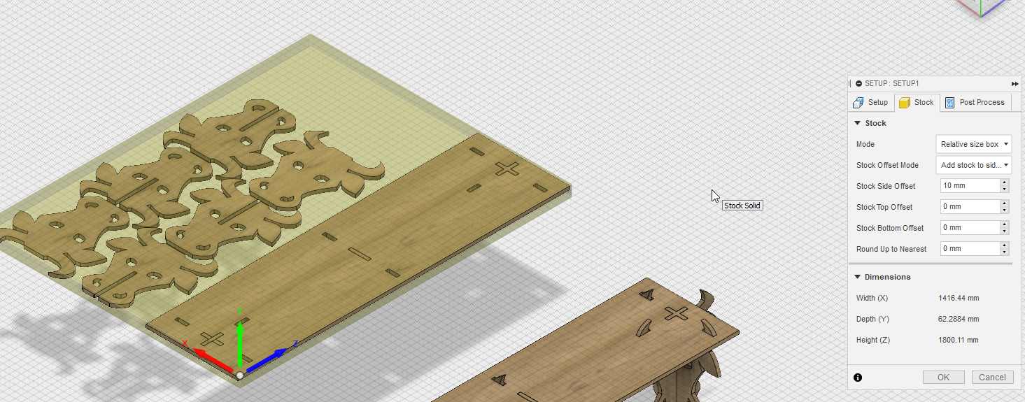
I select the right oriengation. I select the right origin on a stock point. I create the stock material with 10mm of extra space on the sides.
Then I select the contour strategy in the 2D strategies and select the lower line of the inside of the eyes and nose.
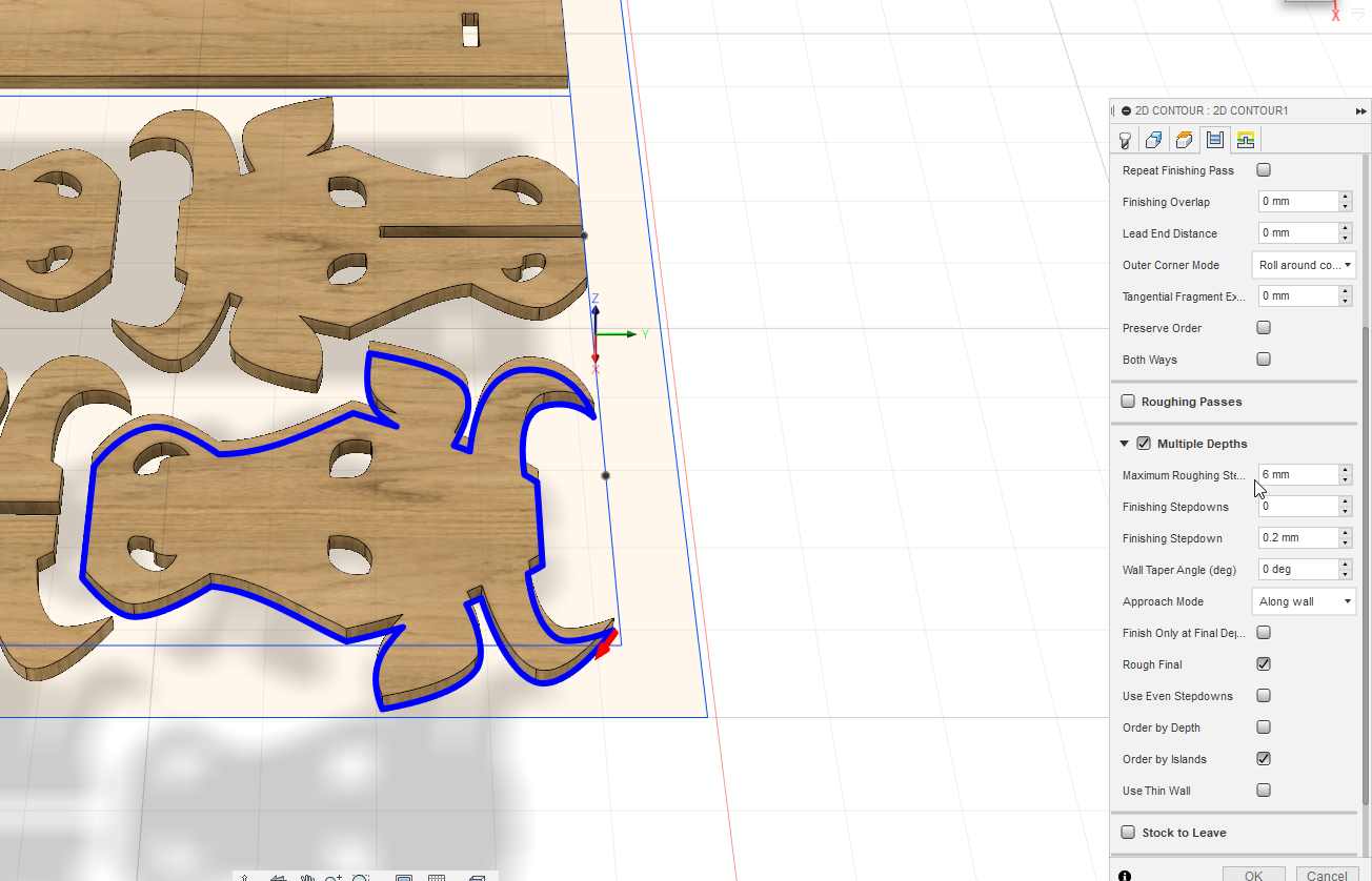
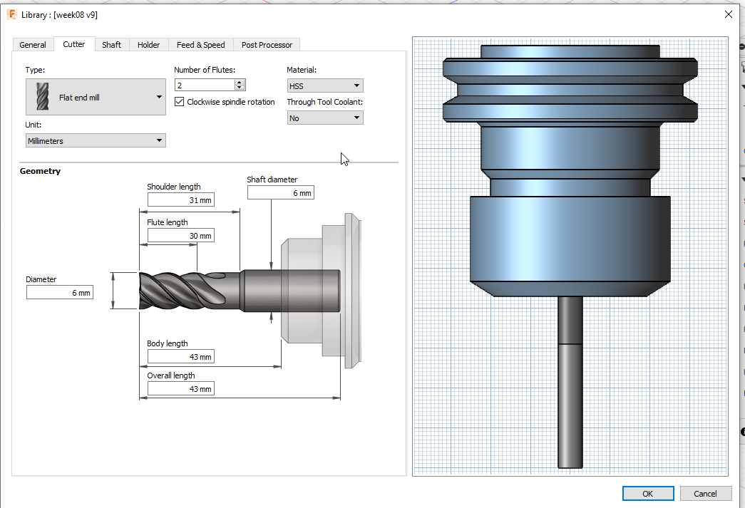
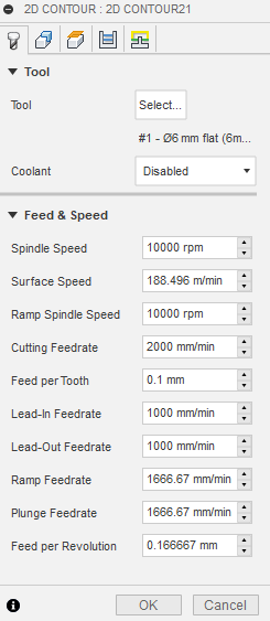
I have previously define the flat-end mill. It has 2 flute , a diameter of 6 mm and I work at a feeding rate of 2000 mm / min.
The speed displacement
As my material is 18.4 mm I select the multiple depths and a roughting step of 6 mm
I select another strategy for the 2d pocket.
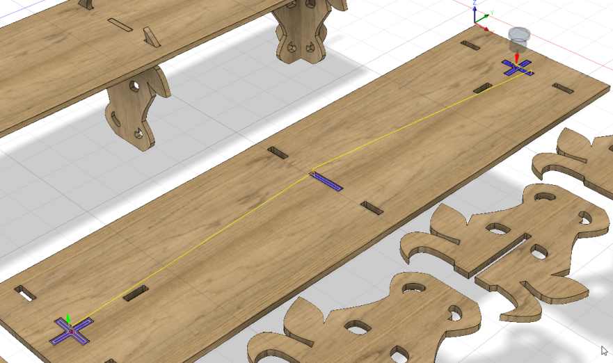
I will not go in detail but I have separate all the operation to be sure they are done in the order I want.
I’ve checked everything with the simulation tool.
I decided to export the operation in several seperate file so I can check all the operation and remove the part as they are finished.
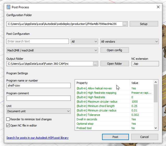
To create the gcode, you select all your strategies and click on post-processor.
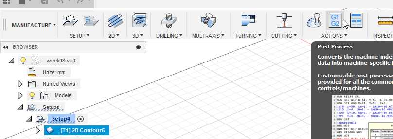
I select the mach2 post-processor. It generates a gcode compatible with my CNC, but I have to do some minor correction. Later I will write a dedicated post-processor.
Then I have a gcode file, I transfer it to a usb memory that I plug in the remote control of the CNC.
CNC
It’s a Big CNC, Working area : 2,5m * 1,5m plus a 2,0m rotational axis.
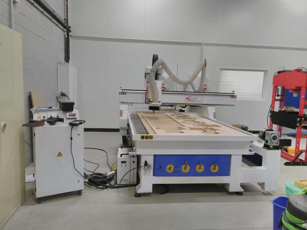
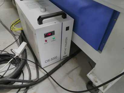
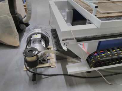
Composed of several units :
A cooler for the spindle motor.
A dust collecting system .
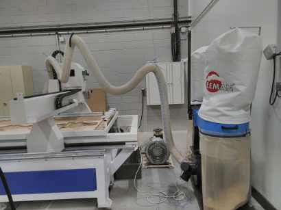
A vacuum table .
A tool changer .
The control unit and the remote control .
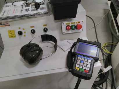
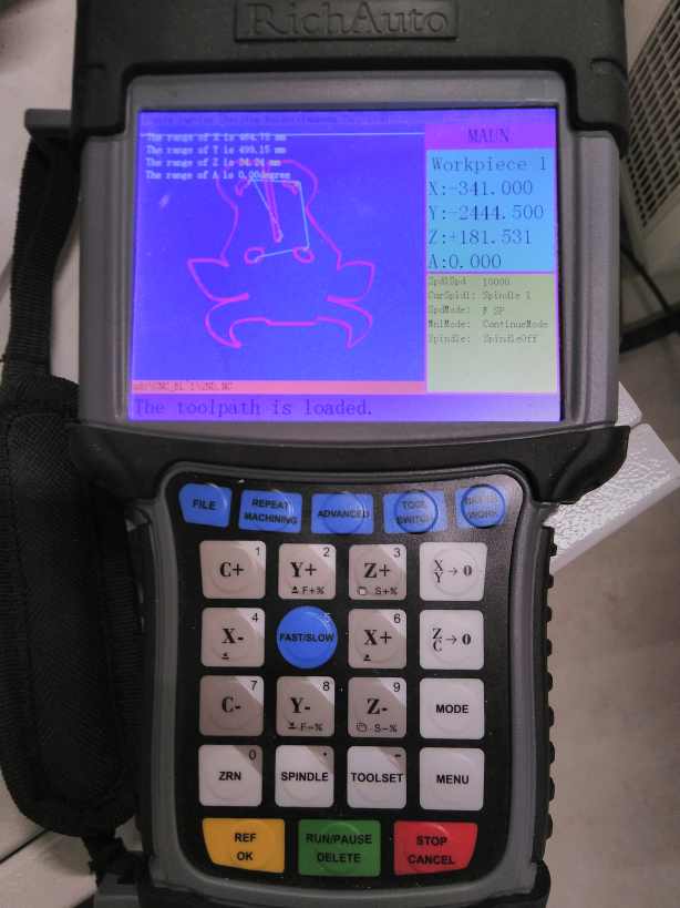
To control the position you click the X,Y or Z arrow the + or - invert the direction of the motion. The fast/slow key change the motion key when you continuously press the motion key and when you make a short click it modify the precision of the displacement.
The XY->0 fixed the G54 home in X and Y The ZC->0 fixed the G54 home in Z
The C letter is a wrong labelling it should be B for the rotation along the Y axis.
The Toolset is an automatic Z , you have to use an electric sensor that measure the contact between the spindle and the sensor. It’s a precise way to determine the Z.
The Toolswitch allow you to change of tool. The tool changer has 8 position.
The File allow you to select your file on the usb key. You confirm with the yellow OK key. And you start the job by clicking the green run/pause key
But for this week assignement I keep it simple with only the tool #1.
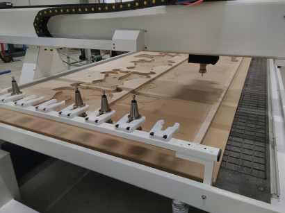
I fixed the material on the sacrificial layer with screws and by activating the vacuumtable. But I’m pretty sure that only with the vacuum table it would have worked without any problems.
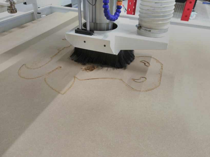
I made a first test on a MDF.
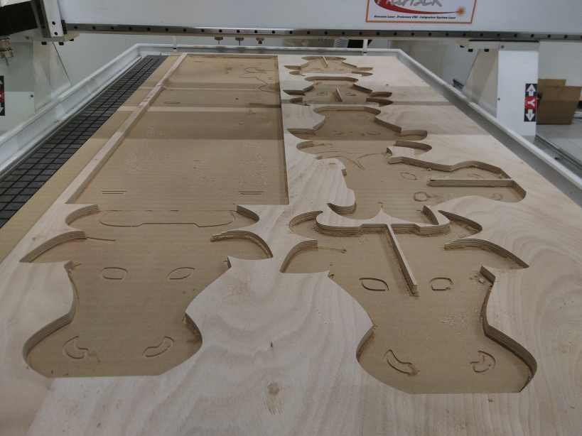
Then I work on a more noble wood.
It fit correctly but I had to use an hammer.
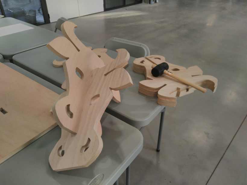
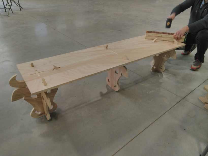
In real situation :
Other tutorials I had written
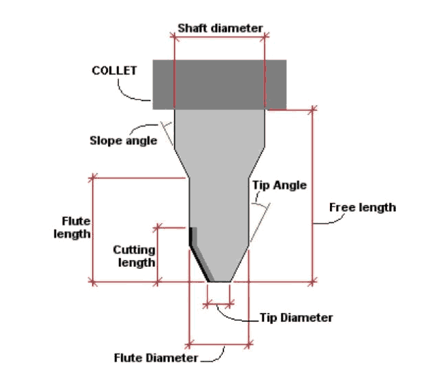
I have written several tutorial on the CNC milling subject : Introduction to cutting tools . I made a copy paste of the one on the cutting tools below.
Cutting tools come in a range of sizes, materials, and geometry types.
It is generally more efficient to use a combination of different toolpaths and tools to achieve a detailed model rather than assuming that a small tool with a smaller stepover is the only way. Often, a larger tool can achieve better finish results.
In end milling, the cutter generally rotates on an axis vertical to the workpiece. Cutting teeth are located on both the end face of the cutter and the periphery of the cutter body.
A ball nose end mill, also known as a spherical end mill or ball end mill, has a semisphere at the tool end. Ball nose end mills are used on workpieces with complex surfaces.
Choosing flat end mill vs. a ball end mill will determine the characteristics of the tooling marks (or lack thereof) on your model. Most jobs will benefit from strategic use of multiple size and shape tools for milling different features. End Mills are often used for roughing and 2D cutting and V-Bit and Ball Nose cutters are often used for finishing operations.
End geometry
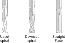
There are up-cut, down-cut, compression cut end mills with varying numbers of flutes. End mills are intended to cut horizontally.
Up-cut, down-cut and compression cut determine the way the chips (cut material) are ejected and the smoothness of the surface. With an up-cut end mill, the chips will be ejected upward and the bottom of the material will be smooth. The down-cut end mill is the reverse by puching the chips downward and the top of the material is smooth. The compression end mill creates a smooth surface on top and bottom, which is perfect for pre-laminated woods.
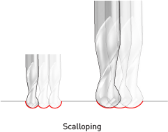
End mills come in a variety of shapes. The most common are flat end mills and ball end mills. Flat end mills will cut flat areas with no scallops. However, they leave a terrace-like scallop on non-flat surfaces. Ball end mills will leave smaller scallops for the same stepover value on sloped surfaces, but they will also leave scallops on flat areas.
Models can be tooled with a combination of flat and ball end mills. If only one tool will be used for all surfaces a ball end geometry will give a more consistent overall feel and smooth result.
Flat end mills can be Center Cutting and Non Center Cutting: Center cutting square endmills are essential for plunge milling. Non-center cutting mills are used only for side milling.
When choosing a ball end mill always chooses the largest size available. For the same stepover, a larger tool will leave smaller scallops, thus giving a smoother result. For a generally smooth model with some areas of fine detail, a large tool should be used for the overall job and a smaller tool should be used only to clean out detailed areas.
Larger tools cut more cleanly, have larger clearance, and stay sharp longer. The velocity of the cutting edge on a larger tool is higher for the same spindle speed.
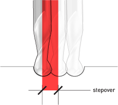
Stepover
Stepover is the distance the tool moves over between subsequent passes.
The stepover value (along with tool size) will determine whether the model has a smooth finish, or tooling marks are visible. It will also directly impact cutting time. Models with a smaller stepover take longer to cut.
Stepdown
The length of the cutting area within the tool determines how deep the material can be cut in one operation –this is called the maximum stepdown. This stepdown value will only be used to its maximum when the material that is being cut is soft; for harder materials a smaller value is often required, setting the toolpaths to mill away layers of materials in separate passes.
Flute geometry
While the number, direction and type of flutes that a cutting tool has can vary widely, the tools most commonly used have two flutes and are up-cut spirals.
Some projects may benefit from other types of flute geometry. Contour cutting MDF or plywood sheets would benefit from down-cut spirals as the tool would push the material against the CNC machine table as it cuts rather than lift it.
Number of Flutes
Single Flute - Allows for larger chiploads in softer materials
Double Flute - Allows for better part finish in harder materials
Multiple Flutes - Allows for an even better part finish in harder materials
As the number of cutting edges increases, your feed rate should increase to prevent burning and premature tool dulling. More flutes reduce chip load and improves surface finish if feed rate remains the same. The most common flute numbers for general milling operations are two (better space for chip ejection) and four (better surface finish).
Examples of applications using end mills:
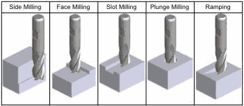
Choosing end mills
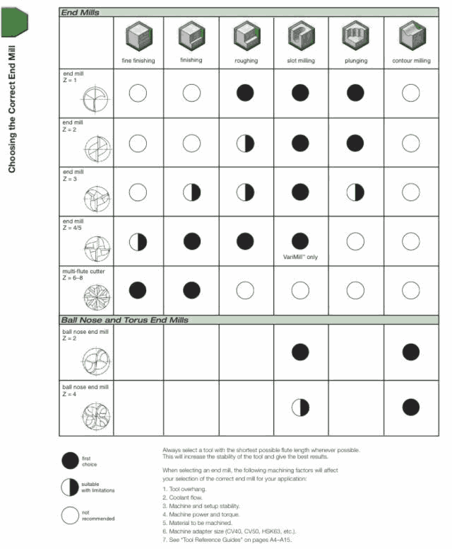
Material: end mills are made either out of cobalt steel alloys (known as high speed steel, or HSS), or from tungsten carbide in a cobalt lattice (colloquially shortened to “carbide”). The latter option is considerably harder, more rigid, and more resistant. Carbide tools can be run at speeds 2 to 2.5 times faster than HSS tools. When using carbide tools ensure that your machine tool is rigid with a solid spindle and that holders have little or no runout. Due to the brittle nature of carbide and the speeds at which carbide tools are typically run, rigidity is critical to prevent tool breakage.
Coatings: carbide cutters may be further coated with ceramics such as titanium aluminum nitride (TiAlN, aka AlTiN), titanium nitride (TiN), titanium carbon nitride (TiCN), and so on. Of these, the bluish-gray TiAlN coating is most common one, and by the virtue of reducing friction and improving hardness, it boosts the speed of metal cutting by up to 20%. It extends tool life.
This document is based in different sources. On of them is the online documentation of the Hardvard FabLab: http://www.gsd.harvard.edu/#/gsd-resources/fabrication-laboratory/index....
Remarks and comments
I always recommand to test a small part of the CNC milling. MDF means Medium Density Wood, it also means that the density of the wood is homogenous. If you prepare all your parameters for a more dense wood, it will work without any problems for a wood with less density.
The purpose of a test in this case is mode to see the shape and the size. For big assembly it is always a good idea to mill the most difficult fitting assembly as described in the book Make: Design for CNC http://atfab.co/ and https://www.amazon.fr/Make-Design-CNC-Gary-Rohrbacher/dp/1457187426/
Some sketches of some great principle describe in the book
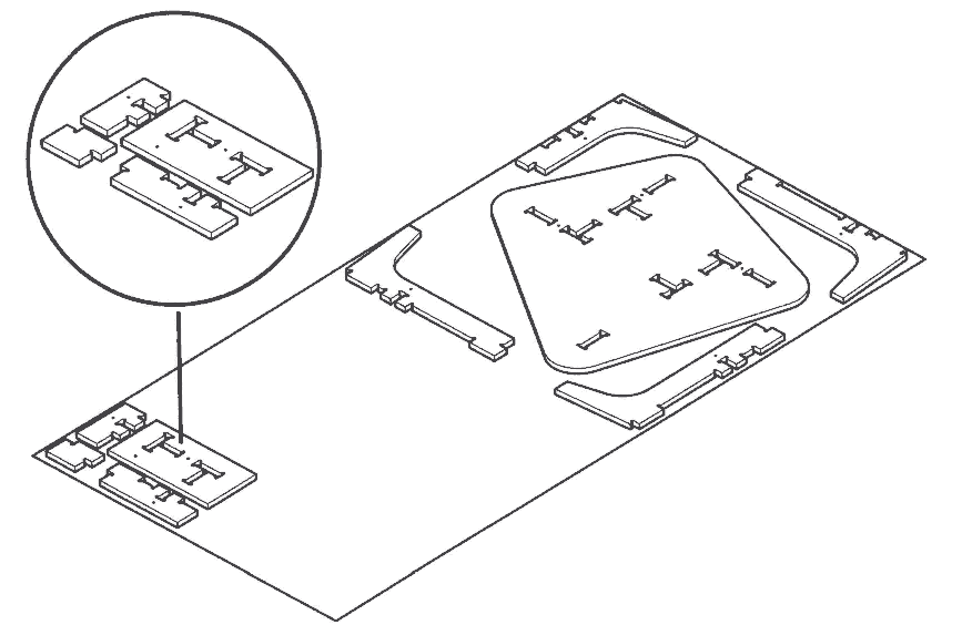
A reduced version of the most difficult fitting assembly is milled. You can then check that your design fit correctly and launch the whole model.
How to find the correct speed parameters ?
After 8 years of CNC milling, you can easily recognise the sound and reaction of material to the milling.
For new materials and new milling bits , I make the design with the parameters close to the same milling bit or to the same material . I start the milling machine at a speed of 10% , that means that the milling machine reads the gcode but modify all the feedrate speed with a 0.1 factor, a speed of 2000mm/min modify to 200mm/min . Then I increase progressively.
Use your ear, it is your best tool.
Your eyes and the smelling will also tell you if you burn the wood : you will have dark buning and it smells the burning wood.
The size of the chips is an important indication. Depending on the operation you want big chips or small chips. A rought pass is extremly different of a final path.
Never leave the device working alone with a new material or a new milling bit. With wood the fire can come really quickly.
To find the correct milling bit for certain operations is a long process, you will find plenty of forum talking about it (some are correct and many are wrong !). The only good answer is to try, you will develop this skill on long term !
If you want to discover other milling strategies, take a look at WEEK10 Molding and casting , That week I milled a highly detail model that need several differents strategies.
Another big remark : To have a good result with milling your design had to be design for milling. It takes a huge effort to design something with a manufactoring technique in mind. You do not design something just for it too look nice, you have to think about the assembly, the limitations, the angles, that you have sharp corner in certain situation but not for inside corner…
Conclusion
I design this furniture with many things in mind. It looks simple but it has been optimised for CNC milling. It does not need many strategies and can be milled quickly with a few passes .
files
My 2D drawing on Inkscape cow_cnc.svg
The fusion file week08v9.rar or the non compressed file : week08v9.f3d