9. Embedded programming
This week I had to discover more about the microchip and how to program them. I have to program the board I made on week 07, and test several IDE. Upload some code with an ISP programmer, upload a bootloader and try to upload with FTDI.
Arduino
I installed Arduino IDE.
Then I add the Attiny board adress in the Board Manager : https://raw.githubusercontent.com/damellis/attiny/ide-1.6.x-boards-manager/package_damellis_attiny_index.json

I select the correct board.
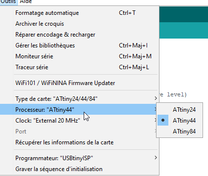
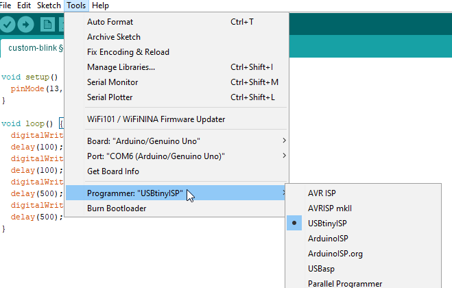
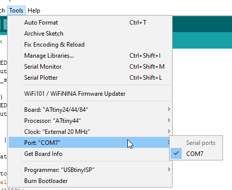
I select the correct ISP programmer, mine is a USBTinyISP
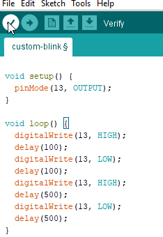
I write a simple code :
int pin = 7;

void setup() {
  pinMode(pin, OUTPUT);
}

void loop() {
  digitalWrite(pin, HIGH);
  delay(100);
  digitalWrite(pin, LOW);
  delay(100);
  digitalWrite(pin, HIGH);
  delay(500);
  digitalWrite(pin, LOW);
  delay(500);
}
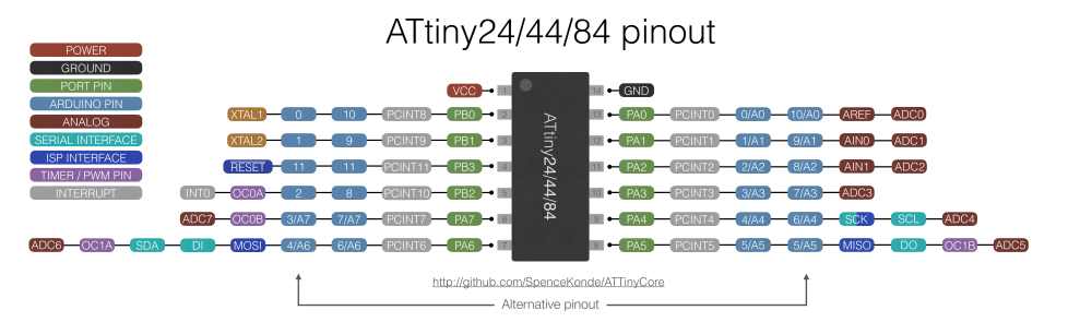
I write the pin number in a variable, because I find several pinout value for the same pin number !
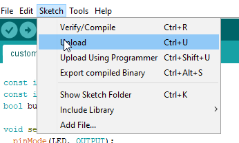
I compile the code. Shortcut ctrl-r
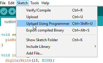
I upload throught the ISP interface. Shortcut ctrl-shift-u
I connect the ISP with the Board. And add also the FTDI connection to be sure to have enought power.
And now my LED is blinking.
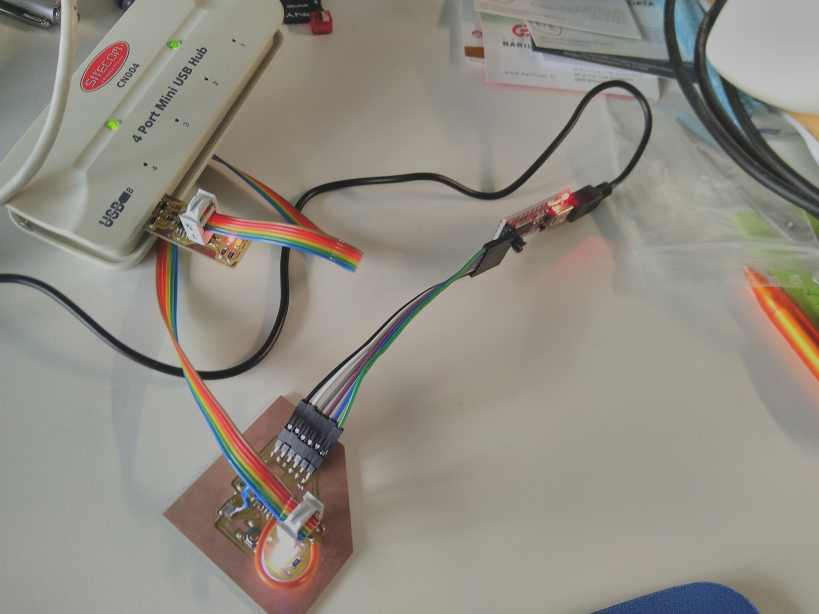
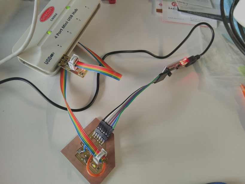
And it works .
I made also another code to test the button, to make single blink on the LED.
const int LED = 7;
const int button = 8; // 2 ou 8
bool button_state = 0;

void setup() {
  pinMode(LED, OUTPUT);
  pinMode(button, INPUT_PULLUP);
}

void loop() {

  button_state = digitalRead(button);

    if (button_state == LOW) {
      digitalWrite(LED, HIGH);
      delay(1000);
    }
    else
    {
      digitalWrite(LED, LOW);
    }

    delay(10);

}
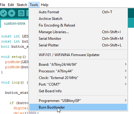
I upload the bootloader and uplaod the following code by ftdi to test the system.
and upload to the board
It also works.
Visual Studio Code
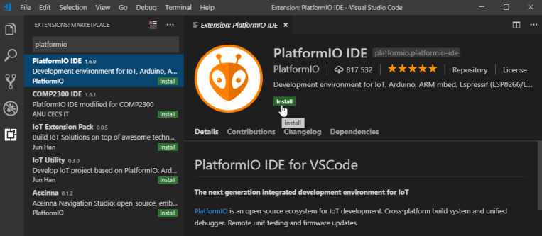
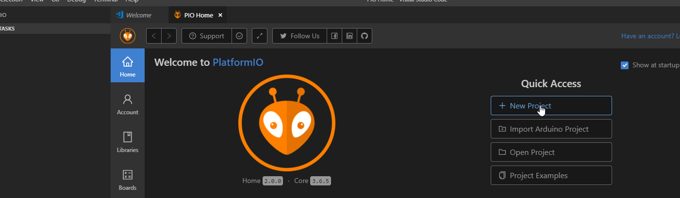
I download and install Visual Studio Code

I install the PlatformIO extension
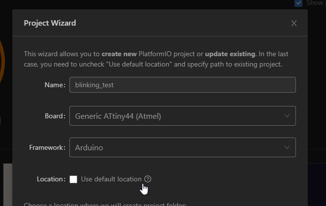
I create a new project
And select the Attiny44 board and the Arduino environment.
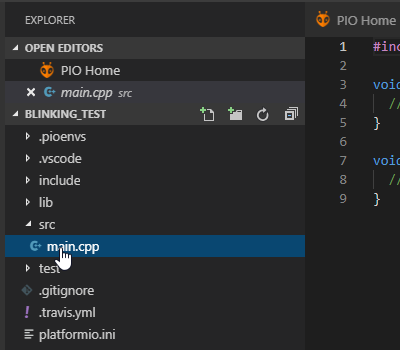
I select the main.cpp file in the src folder
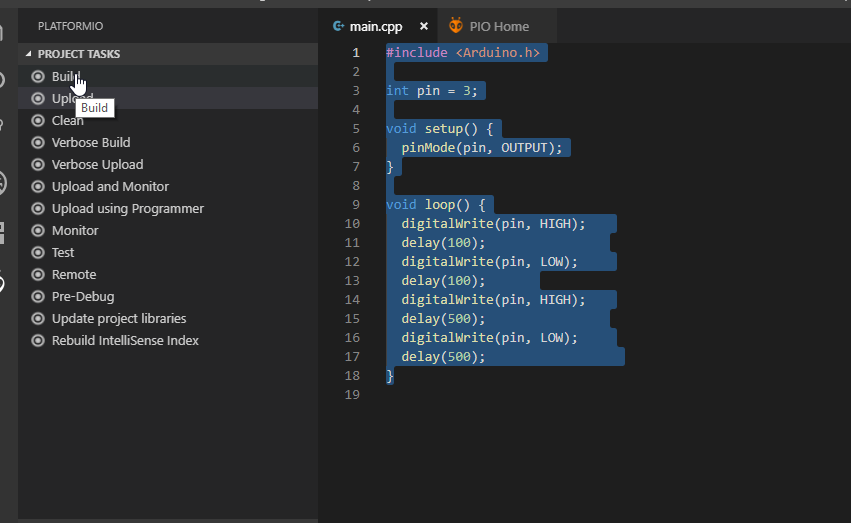
Here I put another blinking code and I have to change the pin number. Here for the led it’s 3.
#include <Arduino.h>

int pin = 3;

void setup() {
  pinMode(pin, OUTPUT);
}

void loop() {
  digitalWrite(pin, HIGH);
  delay(100);
  digitalWrite(pin, LOW);
  delay(100);
  digitalWrite(pin, HIGH);
  delay(500);
  digitalWrite(pin, LOW);
  delay(500);
}
I click on Build
Then on upload and monitor .
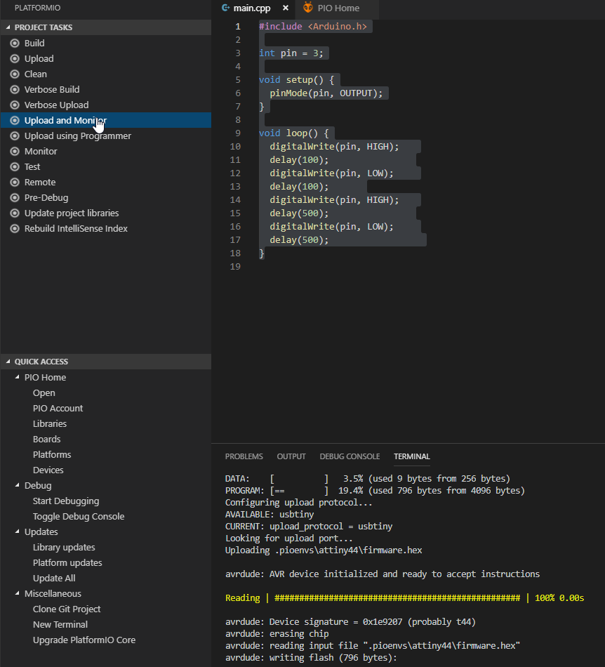
And it flash the Attiny and the code works , it blinks.
It has works, but I think it has use the FTDI connection :
I have not yet find out how to upload throught the ISP with platformIO.
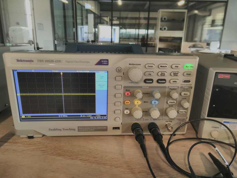
Oscilloscope
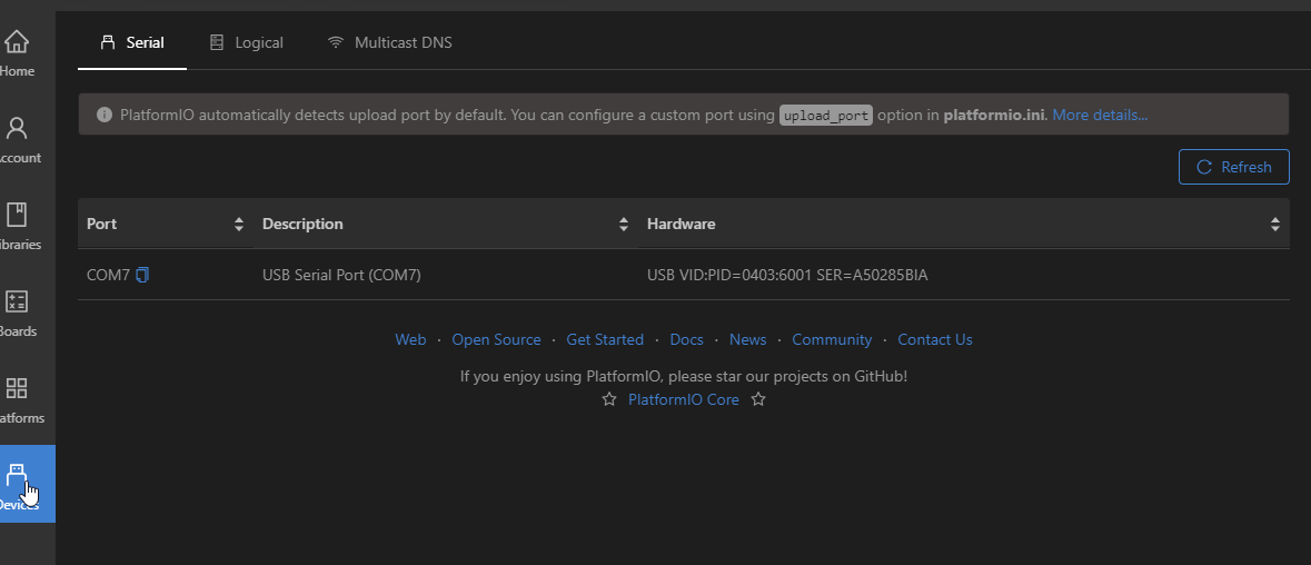
I measure several points on the oscilloscope. But I have only 2 hands. I can’t take picture at the same time and touch the correct point with the probes …
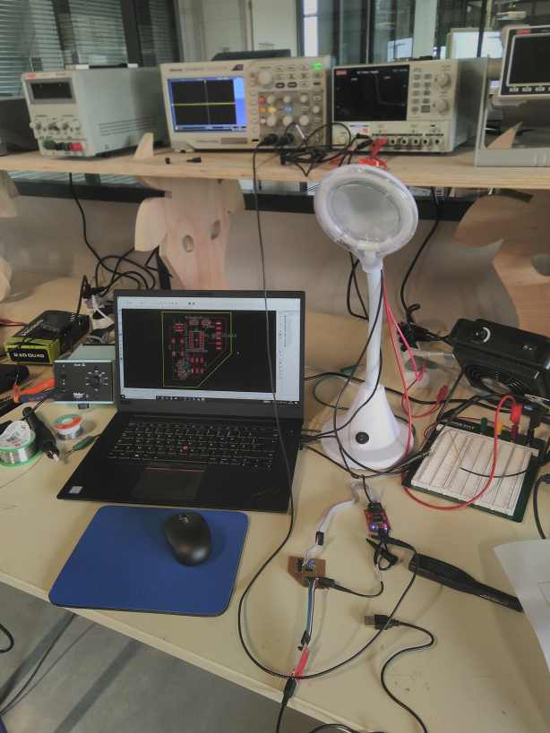
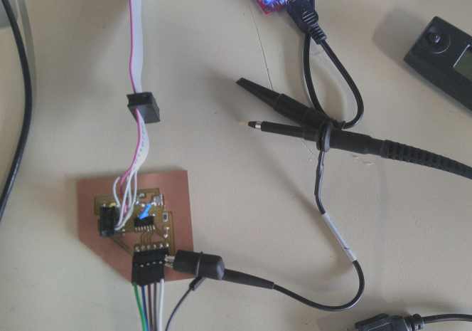
I switch to the logic analyser that have some really tiny probe. It’s a Saleae 8 channel Pro. https://www.saleae.com/
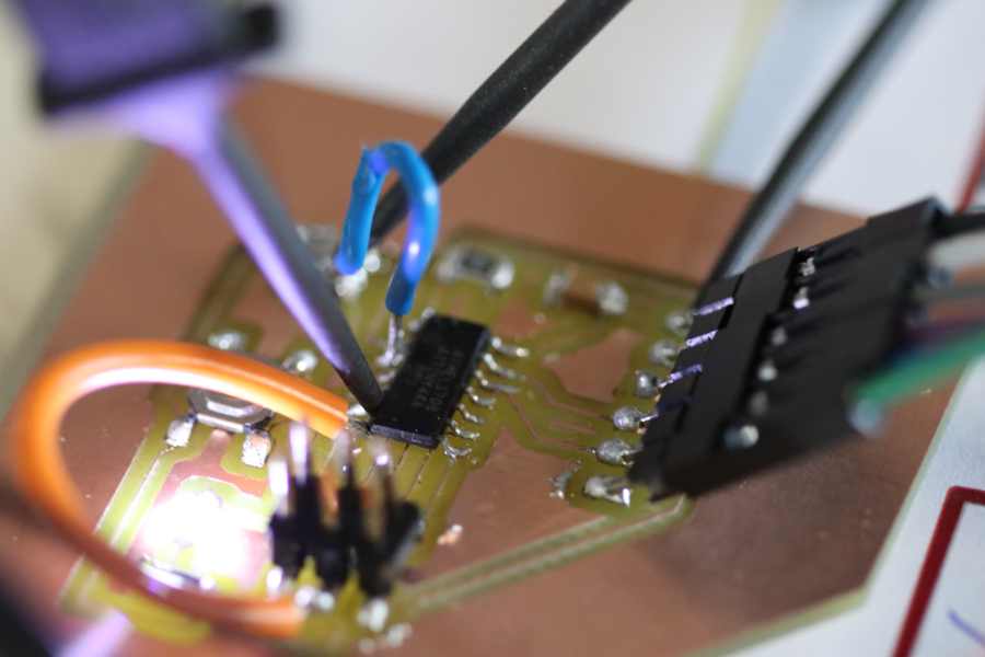
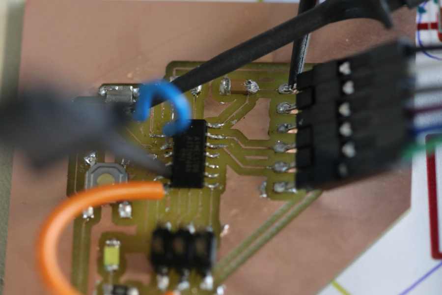
1 connect the ground, the pin connected to the LED and one connected to the resonator.
I take a measure.
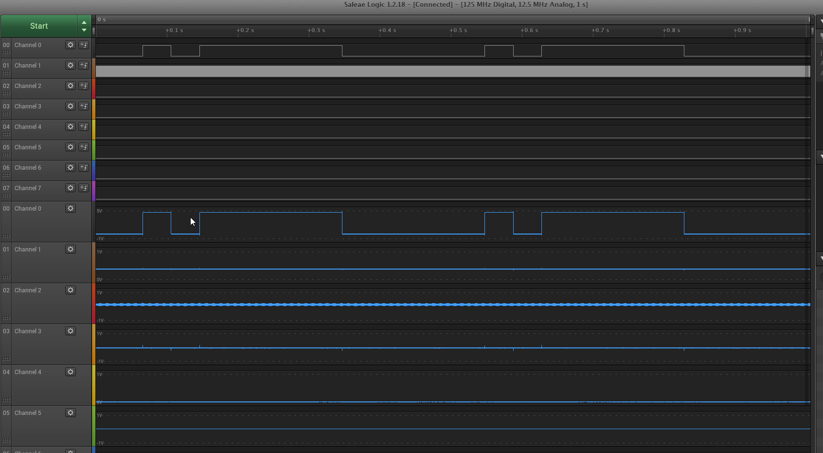
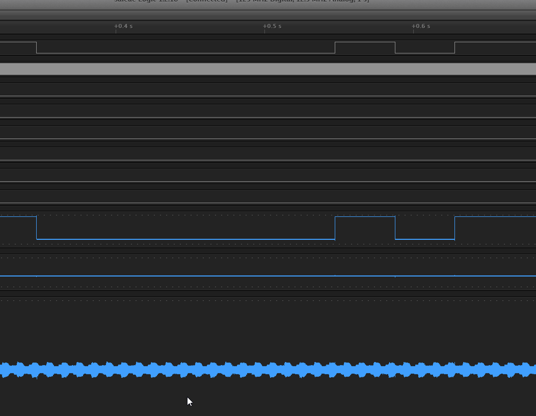
I can see the ON/OFF sequence on the LED pin. And also a shape of the clock on the resonator pin.
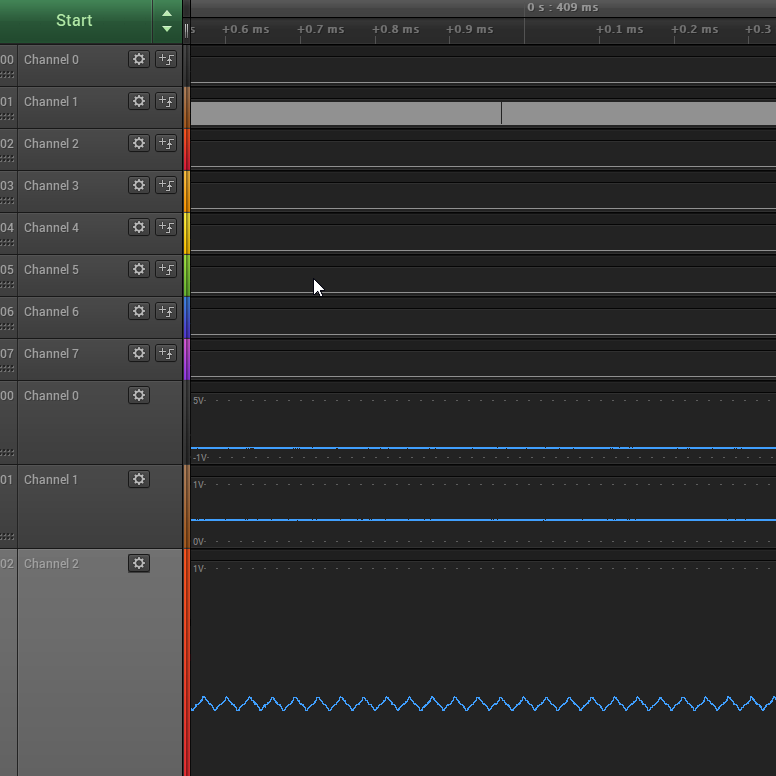
A first zoom give a more clear idea of the clock.
20 Mhz should have a period of 0.05 micro second so 2 cycles per 0.1 ms
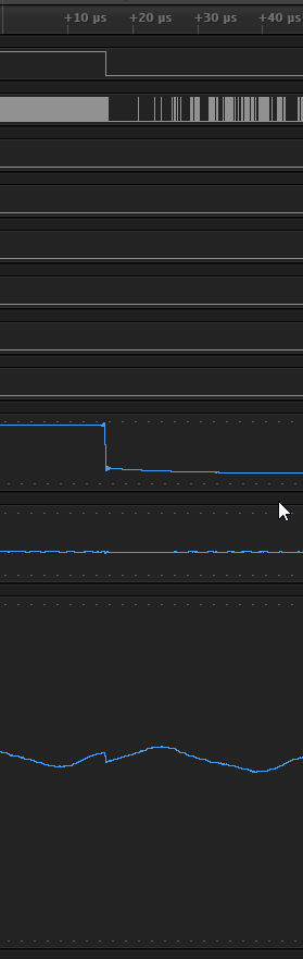
Then you can see some strange things when it switch from on to off.
Microcontroler
As described by wikipedia :
A microcontroller is a small computer on a single integrated circuit. In modern terminology, it is similar to, but less sophisticated than, a system on a chip (SoC); an SoC may include a microcontroller as one of its components. A microcontroller contains one or more CPUs (processor cores) along with memory and programmable input/output peripherals. Program memory in the form of ferroelectric RAM, NOR flash or OTP ROM is also often included on chip, as well as a small amount of RAM. Microcontrollers are designed for embedded applications, in contrast to the microprocessors used in personal computers or other general purpose applications consisting of various discrete chips.
A nice comparison of different microcontroler of the AtTiny Family : https://en.wikipedia.org/wiki/ATtiny_microcontroller_comparison_chart
The AtTiny44 is a 8 bit low-power microcontroler.
The AtTiny44 has 14 pins : 12 are GPIO meaning 12 pins that can be input or ouptut, 8 are ADC meaning they have an analog to digital conversion with a resolution of 10 bits it will gives a value from 0 to 1023 ( 2 exp 10 = 1024).
The pins are classified in 2 part the A and the B. A is related to the 8 ADC pins.
B are more specialised for serial communication and clock , you can have up to 4 bit bi-directional port.
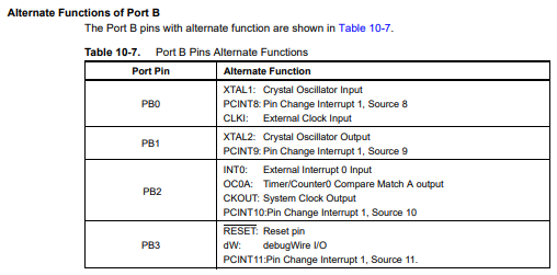
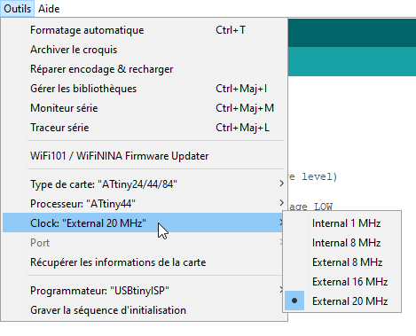
It has an internal clock but I will use the maximum clock speed 20MHz with an external resonator.
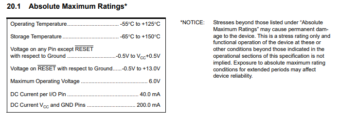
Below a screenshot of the tolerance :
The following diragram gives an overview of all the infrastructure of the micro controller.
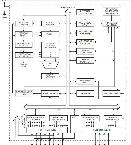
All parts are described in depth in the pdf : http://ww1.microchip.com/downloads/en/DeviceDoc/doc8006.pdf
Documentation discoveries
I read the AtTiny44 documentation : http://ww1.microchip.com/downloads/en/DeviceDoc/doc8006.pdf
I have already worked with some microcontroller like atmega, esp32,…
I often need to be in low power mode and find the best techniques to put the device in deepsleep.
I found why the watchdog is limited to 8s , page 47, table 8-3.
It’s better for the unconnected pin to be put in pull-up , page 58, 10.1.6
For this schematic, I still don’t understand why I need a resonator, as the Attiny as several internal clock. But I understand why I need to connect it to PB0 and PB1 , page 65, 10.2.2
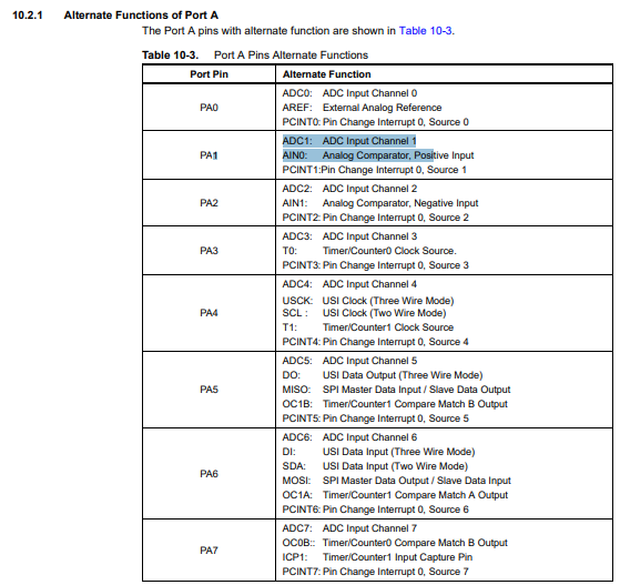
I undestand why the ISP is using the pins PA4 & PA5 , to use the Universal Serial Interface described in 14 , page 117. And more specifically in 19.5 page 163 . But why to use the PA0 & PA1 for the FTDI ? Maybe because they are not any USI pin left. I think I need to use a serial software system to communicate with the FTDI on PA0 & PA1. I don’t get a buffer/register as I would have on PA4 & PA5.
I found the value of 10kOhms of impedance for the input for ADC, page 139, 16.8 .
I found the signature Bytes that were so difficult to check for my first board, page 162, 19.3.1 .
I was not aware :
-
it has an analog comparator. I will try later how to use it. Especially for interupt features, describer in 15, page 129.
-
it has on the ADC a programmable gain stage. 16.2 page 132, I did not find how to use it. A part was described page 145, Table 16-4 & 16-5 .
Files
Arduino blinking : custom-blink.ino
Arduino Button-led : button-blink.ino
PlatformIO blink file : main.cpp