Week 12: Output devices
04/10/2019 - Stéphane Muller
Group assignment: measure the power consumption of an output device. Individual assignment: add an output device to a microcontroller board you've designed, and program it to do something.
Research
For this week I wanted to learn how to operate a stepper motor. I'm not going to use a motor in my final project, but I'll be using PWM with a lamp. So my goal is to learn software and hardware PWM. Ultimately I'm going to design a casing for the motor and connect it to a set of gears. I love seeing gears turn.
Some interesting ressources I found for this week:- A great video explaining how hybrid stepper motors work
- The datasheet for the motor I'll be using
- A video explaining how MOSFETs work
- A little tutorial on how voltage dividers work
- Documentation from a former student about the stepper motor
- A fuse calculator
- A tutorial on fuses
Planning and list of tasks
- Group assignment
- Designing the board
- Programming the board
- Testing the motor
Step by step
Group assignment
You can measure power consumption in a number of ways. Power is equal to the tension multiplied by the intensity, so, knowing the voltage applied to a DC motor for example, we could just measure the intensity and multiply both. So we plugged the motor to a generator and plugged the multimeter in parallel (see schematics below).
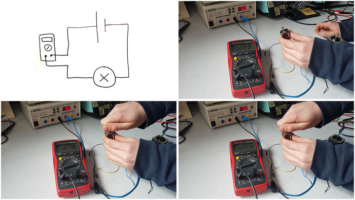
When it's free running (no load), the motor requires 62mA. That gives us 5V x 0.062A = 0.31W.
When we apply some resistance (loaded), the motor requires 1.05A. So 5.25W.
When we completely block the motor (maximum load), the motor requires 1.87A. So 9.35W.
Designing the board
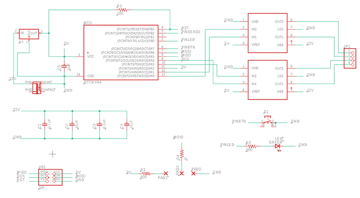
I started my board with Neil's design and added an LED (to experiment with PWM and test the board), a button to interact with the motor (on/off/reset position) and a potentiometer to control either the position of the gear or its speed.
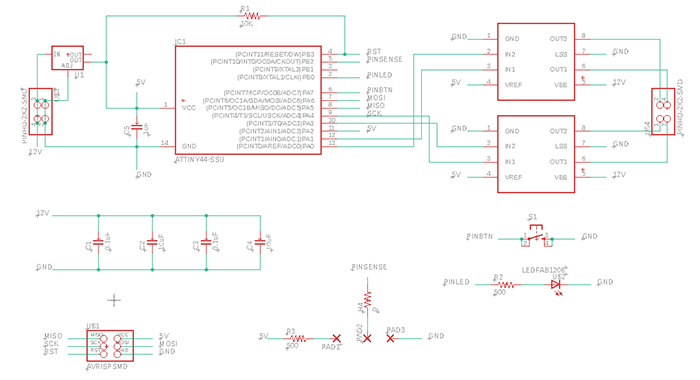
I added 3 pads to symbolize the linear 20K potentiometer I found. It was easier than trying to find the right footprint. There just had to be a 5mm gap between the pads.

So I wired the middle pin of the potentiometer to one of the ATTiny's pin and the other two to Vcc and ground. I calculated the voltage range I would get depending on the potentiometer's value and I thought I would get a short when the value was 0, so I added a 500Ω resistor. And now that I'm writing this I realize this is wrong. There will always be a resistor between Vcc and ground with the potentiometer... I was a little too cautious here (better that than the alternative I suppose). Anyway, what is still interesting is to know how to calculate the voltage on the output pin of the potentiometer. The formula goes like this (source):
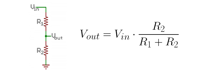
In my case, since I added the 500Ω resistor, voltage would vary between 0.024 and 4.88V.
Always look at the datasheet to check if the pin you're using matches the application you want... I just realized I attached the potentiometer reading to a pin that doesn't do ADC. I'll have to use a fly wire to fix that...
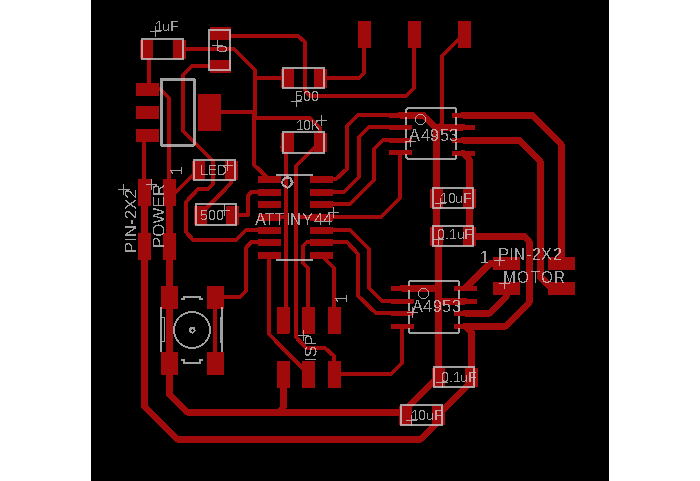
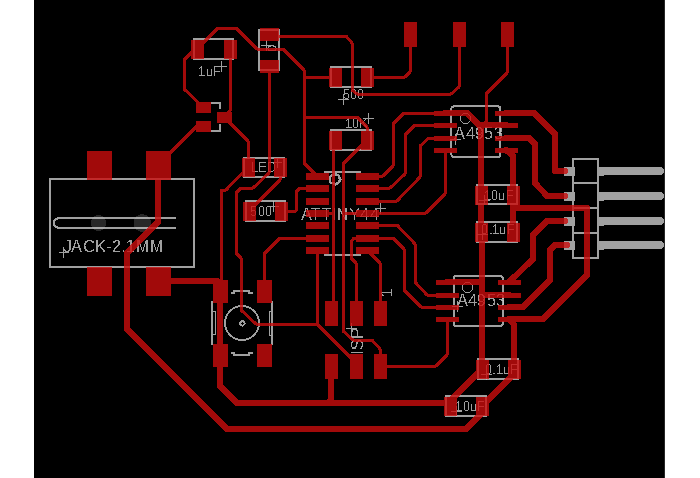
This board is a little more complicated than those I have done before, it wasn't easy to route, even with Neil's board as an example.
I tried to upload Neil's code to test my board and it wouldn't work. I checked for shorts and found one near the ISP header (between GND and SCK), so I took the header out, scraped off some copper and resoldered the headers. After that it still wouldn't work so I checked the voltage and unfortunately I used the wrong regulator... it only delivered 3V.
So I decided to go back in Eagle, improve my board and mill it again. This time I used the right voltage regulator, a power jack and a row of 4 pins to connect the motor.
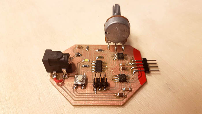
And here is the final (working) board! At least the whole process gets easier every time. And I'm quite proud of that one, I have to say!
Programming the board (part 1)
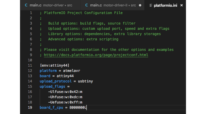
After using the Arduino IDE for a while, I decided to switch to VSCode/Plaformio because (among other things) it enables me to set the fuses myself in the ini file of the project.
I started out by trying to decode all that was going on in Neil's code and using it to test my board. I just modified it a little bit to have the motor make one complete turn clockwise (200 steps) when I press the button. Also, this time I just wired the button to a pin without any resistor and used the internal pull-up resistor. So I had to declare the right pin as an input (which they are by default) and set the corresponding bit to 1 in order to enable the pull-up resistor.
PORTA |= (1 << BTN);I understood what Neil was doing in the code, but some things didn't add up. In the example below, we send a PWM modulated with the on and off delays. The ratio between the on and off delays determines the level of the pulse. If on is longer than off, the pulse is higher. The PWM_count is the length of the pulse. Shorter pulses make the motor spin faster.
void pulse_ApBp() {
clear(bridge_port, A2);
clear(bridge_port, B2);
set(bridge_port, A1);
set(bridge_port, B1);

 for (count = 0; count < PWM_count; ++count) {
    set(bridge_port, A1);
    set(bridge_port, B1);
    on_delay();

    clear(bridge_port, A1);
    clear(bridge_port, B1);
    off_delay();
    }
}
What I haven't understood however is why a pulse is 30µs long. Where can I find that information or calculate it?
When I tested Neil's code I had some unexpected result. My stepper motor has a 1.8° step, so 200 steps should make a complete turn. So when I sent the following code, I was surprised the motor made 4 turns instead of 1...
step_count = 200;

for (i = 0; i < step_count; ++i) {
step_cw();
}
I asked these questions to Neil during the review but his answer wasn't satisfying at all... He told me I could try measuring the back-EMF of the motor or just try many different values. I wasn't able to find any tutorial or info on the back-EMF thingy so I tried a bunch of different values... and couldn't find any combination that worked properly. After hours of trying I decided to give up before going completely insane.
My code works as long as I take into account that one turn is 50 steps. I will have to try with another stepper motor.
Programming the board (part 2)
I wanted to be able to control the position of the motor precisely with the potentiometer, so I had to make an interrupt triggered by the ADC and program the position. As a bonus, I wanted to experiment with PWM and varying the intensity of the LED thanks to the potentiometer as well.
To vay the intensity of the LED I added the following code. I used the ADC to read the voltage output of the potentiometer and launched an interrupt to handle it (exactly the same way I as last week).
ISR(ADC_vect)
{
   static char chr;
   static float conversion;

   measurement = (ADCH << 8) | ADCL;                              // store the result in a variable

   conversion = measurement*200.0/1023.0;
   destPosition = uint8_t(conversion);                            // convert to a position

   conversion = measurement*255.0/1023.0;
   brightness = uint8_t(conversion);

   chr = ADCL;                                                    // ADCL and ADCH need to be read
   chr = ADCH;                                                    // in order to be flushed
}
So I read the value and I map it to the ranges I need. For the position of the motor it has to be a value between 0 and 200 and for the LED it's between 0 and 255.
The variable types used here are very important. Since we're dividing, the result will be a float and the numbers used in the operation need to be floats as well hence the .0 at the end (200.0 and 1023.0). Then I force the conversion from float to int.
The LED abehaved really strangely because I didn't do it properly (the LED was flickering, going bright then off then bright again although I was turning in one direction). And the motor didn't move in the right position... all because of variable types.
To vary the brightness I use this bit of code in the main loop. Works perfectly!
while (1)
   {
      PORTB ^= (1 << LED);
      for(i=brightness ; i<255 ; i++)
      { _delay_us(25); }
      PORTB ^= (1 << LED);
      for(i=0 ; i<brightness ; i++)
      { _delay_us(25); }
   }
}
To change the position of the motor I just tell it to take a step in the right direction depending on the destination position I got from the potentiometer.
ISR(PCINT0_vect)                                                  // what happens when the button pin changes state
{
  uint8_t j = 0;

  if(pinStateChange == 1)
   {
      while (currentPosition < destPosition)
      { step_cw(); }

      while (currentPosition > destPosition)
      { step_ccw(); }
   }
  pinStateChange ^= 1;                                            // the button has been toggled
}

void step_cw() {                                                  // make a clockwise 1.8° step
   pulse_AmBp();
   pulse_AmBm();
   pulse_ApBm();
   pulse_ApBp();

   currentPosition += 1;                                          // track motor position
   if( currentPosition == 50 )
      { currentPosition = 0; }
   }

void step_ccw() {                                                 // make a counter clockwise 1.8° step
   pulse_ApBm();
   pulse_AmBm();
   pulse_AmBp();
   pulse_ApBp();

   currentPosition -= 1;                                         // track motor position
   if( currentPosition < 0 )
      { currentPosition = 49; }
   }
A little video showing off the result!
I have to make further tests, but I think I broke my FabISP. I don't know what happened exactly, since I haven't done anything special... I've always had some connectivity issues but I'm almost sure they were due to the cable connectors and after awhile it would always work. Now it says my board is not connected every single time. I have tried with other boards and had the same results. So in the meantime I'll use my Arduino as an ISP. I made a cheat sheet to remember the correspondance between the pin numbers on the Arduino and the ISP header.
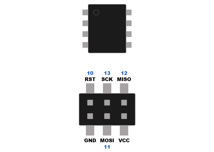
To use Arduino as an ISP, just open the example of the same name and upload it on your Arduino. Wire your board's ISP to the Arduino using the schematics above and then in Arduino IDE select "Arduino as ISP" in the Programmer menu.
My FabISP still works, but there were bad connections with my USB port. Using a USB hub does the trick actually (100% of the time).
Conclusion
This project was harder than I thought, I had a lot of unexpected behaviours. But I'm glad I was able to get to the bottom of all my issues. As usual, I have learned a lot.