Week 4: Computer-Controlled Cutting
02/12/2019 - Stéphane Muller
This week we have our first group assignment! We need to characterize our lasercutter and make test part(s) that vary cutting settings and dimensions.
Individually we have to cut something on the vinylcutter, design, lasercut, and document a parametric press-fit construction kit, accounting for the lasercutter kerf, which can be assembled in multiple ways.
Check out the documentation of our group assignment.
Research
I wasn't very inspired by the concept of press-fit construction kits so I had a look at the Fab Academy archive to see what the previous students did. I'm not a marble fan so I wasn't going to do what Neil showed us (or something similar). I'm more of a Kapla or Jenga fan, but there not press-fit. What I like is the simplicity of it though. So I thought I would do simple polygon shapes. Then I found Javi's page and I thought about fitting designs and how I could improve on it. So I decided to work on a locking mechanism. Something that would really keep the pieces together mechanically.
As for the vinylcutter, I wanted to make a sticker for my laptop. The top is already full of them, but I have some space left on the keyboard, so let's do that! I knew I wanted to do something with my avatar, that's why I vectorized it last week.
Planning and list of tasks
- Tweak my avatar to make a cool sticker
- Cut the design with the vinylcutter
- Design a parametric press-fit construction kit
- Lasercut the press-fit kit
Step by step
Tweaking my avatar
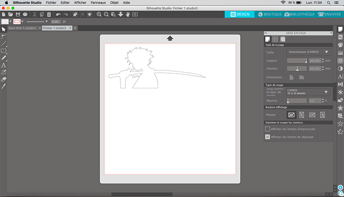
I had already vectorized my avatar on Illustrator, so I just had to isolate the silouhette layer and resize it to the space I have on my keyboard: 105 x 95 mm.
Cutting with the vinylcutter
A vinylcutter is a very versatile but underappreciated piece of equipment. It can cut different materials with great precision. You can even use it to make flexible PCBs. I hope to be trying that next week. In the meantime, let's cut our sticker.
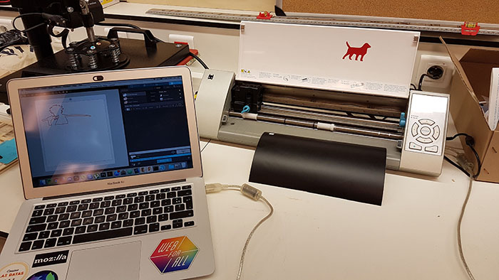
Here at the lab we have a Silouhette Cameo, which you can operate with the software Silhouette Studio. I installed it and plugged the vinylcutter to my computer. I tried to open the Illustrator file and the SVG, but nothing worked. So I tried converting it in DXF using an online app. This time when I tried to open it, it worked.
In its freemium version, Silhouette will only open DXF files...
In the parameters I changed the material I want to cut: black vinyl. The software tells me I need to set the blade's length to 1, so I did and clicked on test to make a test cut. Unfortunately it didn't work, it didn't cut anything. So I tried setting it to 2, but it's only 3 that seemed to work perfectly.
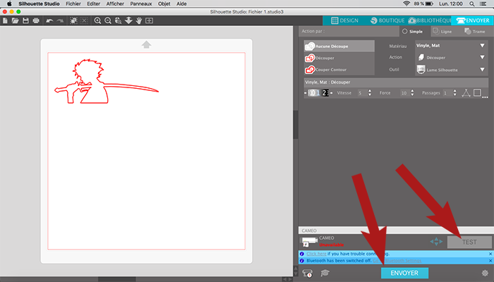
I found a great ressource (in french) explaining the various parameters (force and depth of the cut, number of passes) and what to use for a variety of materials.
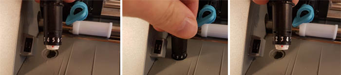
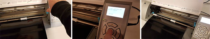
To adjust the blade, just remove it from the blade holder, put it in the adjustment socket and turn until the red line is in front of the desired blade length.
Loading the machine with the material is pretty straightforward. You just need to unlock the shaft (see pictures below), slide the material in and make sure it's taken in by both wheels, lock the shaft again and click on load. Make sure the material is fed correctly (both wheels grip the material).
The cut is very thin so it doesn't go all the way through. It just cuts the vinyl and leaves the paper on which it's glued untouched. Once the cut was done I delicately peeled off the unnecessary vinyl and used transparent transfer paper. Transfer paper has a glue that not as strong as the glue on the vinyl so that you can safely put your design on any object and then just peel off the transfer paper.
Here's a great tutorial on how to transfer vinyl to any surface using transfer paper: tutorial.
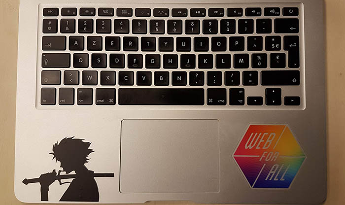
And here is the final product on my laptop!
Designing the press-fit construction kit
Because I had a lot of fun modeling with it last week, I decided to use Antimony! I wanted to go a little deeper this time and really work on a full on parametric model, maybe even go into scripting mode and learn a little Python.
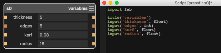
The very first thing I did was to create a script node for my global variables (number of edges, radius, thickness, kerf). So I went into the script to check out how it worked and modified it for my own use.
My goal was to make a polygonal piece and be able to change the number of edges at will. So I started out with a polygon. Then I added a rectangle for the fit. I needed to translate it precisely on the edge so I had to do some geometry research...
The distance h between the center of a polygon and its edge is called the apothem and is calculated as follows (r being the radius of the polygon and n the number of edges):h = r*cos(π/n)
Then I rotated the rectangle by calculating the right angle - depending on the number of edges - and did a polar array transform. Did a boolean difference and checked the result, turned out great! Then I went from 5 edges to 6 and it didn't work anymore. The rectangle was now on each corner and not on the edges anymore! When the number of edges is an even number, the top edge is parallel to the x axis, so no need for a rotation... damn. I needed to go deeper in antimony to figure out how to check a condition.
To do this I went into the code of the rotation transformation. I wanted to modify the angle variable before it was used in the rendering but that didn't work. So I just used my own variable and replaced it in the rendering part of the code. Instead of giving an angle to the node, I gave him the number of edges and made the calculation in the script.
import fab
import math

title('Rotate (Z)')

input('x', float)
input('y', float)
input('_z', float)
input('a', float)

b = ((360/a)/2) if (a % 2) else 0 // if the number of edges is odd, calculate the angle, else make it 0.

input('shape', fab.types.Shape)
output('rotated', fab.shapes.rotate_z(shape, b, x, y))
After that I needed to add a chamfer so that the piece would slide more easily into each other. So I added a triangle big enough to cut the edges and applied the same transformations as the rectangle.
Then the locking mechanism. For that I had to add two small rectangles (with a chamfer as well) into the fitting space. It looked good but there was still something missing. The new shape I added needed to fit somewhere on the other piece. So I had to add a hole of the corresponding size under the fitting space. And there we go!
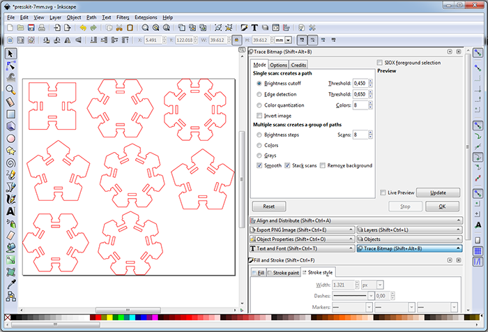
Unfortunately, Antimony can only export a 3D model in STL or a 2.5D height map in PNG. So what I did was export a high quality PNG, imported it in Illustrator and used the vectorize function. Since the lines on the picture were very sharp, the automatic vectorization worked perfectly. We'll see how it goes on the lasercutter...
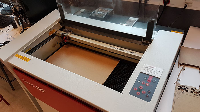
Lasercutting the press-fit kit
First thing I needed to do was import my design into the computer connected to the lasercutter. On this computer there is Inkscape installed so I had to save my Illustrator file in SVG format. Once in Inkscape, I changed the stroke width of my pieces to 1px and the color to 255 red.
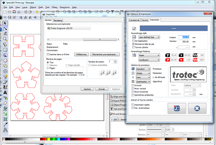
In the software operating the lasercutter, there is a profile for each material specifying the power, speed and frequency of the cut. For each profile there is a stroke color to tell the machine wether to cut or to engrave. 255 red tells the machine to cut.
My first cut worked but the pieces were too small because Inkscape doesn't convert the measurements from Illustrator correctly. Never forget to check the size of the pieces you need to cut...
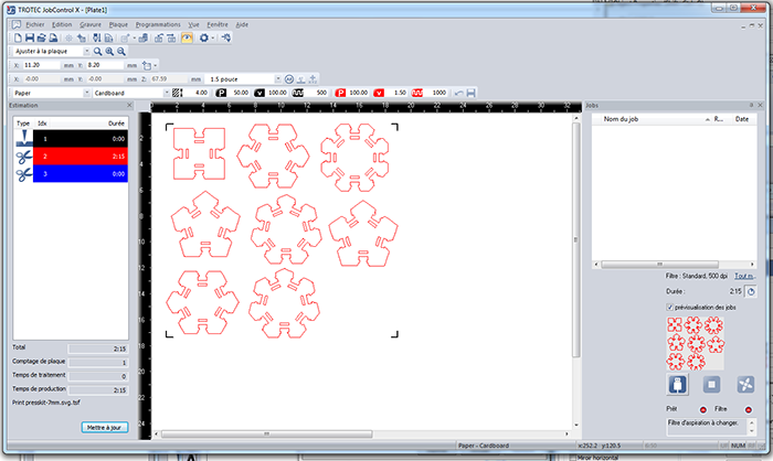
On the lasercutter you need to reset the Z origin (explained in our group assignment) and then link the machine to the computer. Then you're good to go!
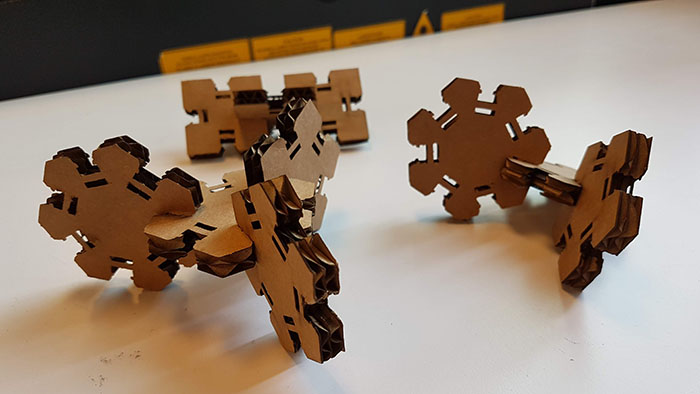
And here is the final result! The pieces fit well together, although you do have to give it a strong push to lock them tightly. The locking mechanism works even better than I thought it would... Once they're locked there's no unlocking them (but you're welcome to try)!
Conclusion
Challenges
Building a complete parametric piece was quite challenging but very interesting. There are quite a lot of parameters (!) to juggle with. All the different file formats are a piece of work... I understand better what Neil meant during the CAD lecture. Although this time DXF actually saved my life.
Achievements
I'm glad my locking mechanism worked, I'm proud of it. It's not necessarily useful with cardboard since most of the time you're going to be prototyping and being able to undo your work is important, but it's a mechanism I could use in 3D printing or with acrylic maybe.
The press-fit construction kit didn't inspire me much in the beginning, but seeing my little pieces assembled the way I did gave me an interesting idea. I could do a kit with atoms to represent molecules in 3D...