Final Project
My final project idea goes from (1) a Whack-A-Mole machine for learning English words to (2) a Camera Trap to capture images of wild life to (3)a self irrigating system and then finally i can be named a true final project: an aquaponic system.
For the ideas and the stories behind these projects, you can see the info here at the ‘Another project’ page. On this page, I will focus on my final project.
The Idea
I have an increasing interest in flowers/plants etc., And in the week of Computer-Controlled Machining, I made an extendable shelf for planting flowers using plastic bottles. But the bottles are too small for growing vegetables. So I think it’d be cool to have an aquaponic system in the office. Hopefully it can treat us with some lettuce to make salads an an afternoon sometimes.
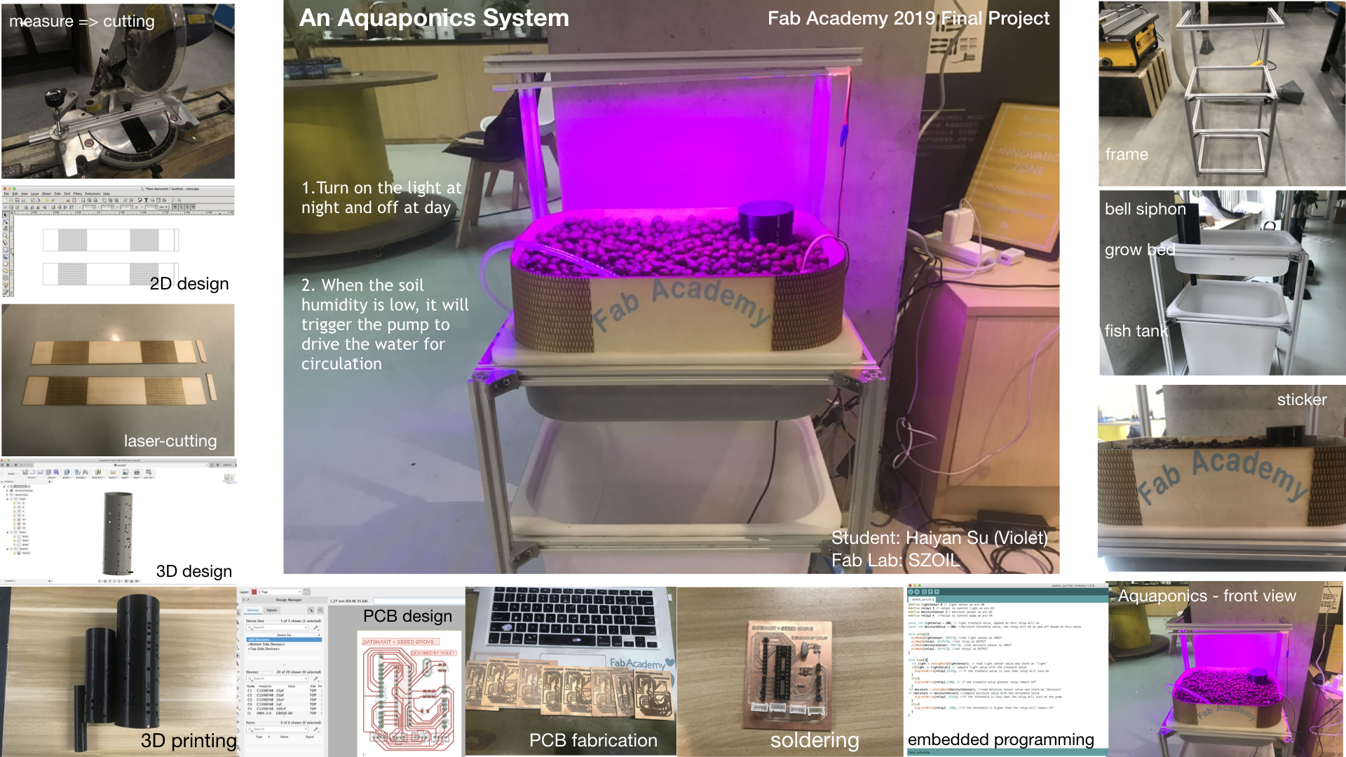
What does it do?
The aquaponics system will allow us to grow vegetables and raise fish at the same time. And the system has two main functions:
- When it’s dark, the light will be turned on automatically so that the vegetables get exposed to a lot of light to grow.
- When the moisture is below than the pre-set level, the water pump will be triggered to turn on and start irrigating.
Who has done what beforehand?
Many many people have made aquaponics systems before. Some made very large aquaponics systems that occupy the whole garden, some made small ones - desktop versions or even smaller versions.
I have got some inspirations and guidances from the following projects.
What did you design?
1. Micro-controller designed with Eagle - Satshakit Micro compatible with Seeed Grove
My initial plan for the micro-controller was to make my own version of an Arduino board. But my friend Salman who is also the local instructor at Fab Lab Kochi suggested I check out the Satshakit. Thanks to Salman’s suggestion, I chose to make a modified version of the Satshakit with some Grove connectors, so that I can use Seeed Grove modules conveniently.
I followed Daniele’s documentation to build my version of Satshakit Micro.
The first attempt I did not read the documents clearly and I chose the grbl version instead of the generic version.
The second attempt I tried to make a Satshakit Micro with the same components that Daniel mentioned in the tutorial. However, after finishing the design on Eagle, I realized the traces were too thin, which will be broken easily (according to my assignments in the previous weeks, the pads came off easily with thin traces.) So I decided to use ATMEGA328P-PU as the IC instead of the ATMEGA328P-AU.
Bill of materials
| Item | Component | Package | Quantity |
|---|---|---|---|
| 1 | ATMEGA328P-PU | DIP28 | 1 |
| 2 | 16Mhz/18pF Crystal | SMD 11.4x4.7mm | 1 |
| 3 | 10k Resistor | 1206 | 1 |
| 4 | 22pF capacitor | 1206 | 2 |
| 5 | 10uF capacitor | 1206 | 1 |
| 6 | 1uF capacitor | 1206 | 1 |
| 7 | 100nF capacitor | 1206 | 1 |
| 8 | pin head 1*1 | 2 | |
| 9 | pin head 1*2 | 3 | |
| 10 | pin head 1*3 | 1 | |
| 11 | pin head 1*4 | 1 | |
| 12 | pin head 1*8 | 1 | |
| 13 | Grove connector | 4 |
With the components listed, I started to use Eagle to design my own PCB board. First of all, I need to get library of these components. I downloaded the OPL_IC.lbr and Seeed-OPL-CONNECTOR.lbr from Seeed Studio’s GitHub OPL_Eagle_Library.
For the PCB design, I referred to the designs of Daniele’s Satshakit micro as well as Seeed Studio’s Seeeduino Lotus V1.0.
I added all the components, added values to each component so that I can tell them apart from each other.

(components added)
And then I used Net to wire them up.

(connect the components using Net)
And then I generated the board file, doing the layout.

In this process, I came across a tiny problem. I couldn’t wire up two traces on the same layer. However, I have to make a one-layer board for milling on the CNC machine. see the image blow.

(traces not connected)
So I added a 0Ω resistor in between to connect these two parts.
And then I began generating the png. files for milling the PCB board. Meanwhile, I also generated Gerber files and sent them to my colleague Carmen at Seeed Fusion team and asked her to help me send it to the PCB plants for manufacturing. (I just wanted to see how it will look like :D, and I guess this is an extra bonus of working at Seeed :D). Luckily, Carmen noticed some faults in my PCB design.

(PCB design faults)
On the above image, you can see three faults:
- No.1 The traces are too close to the pad, which might lead to short circuits.
- No.2 & No.3 Open traces
- No.4 Short circuits
So I optimized the PCB design accordingly.
- No.1 => re-align the traces to ensure enough space between traces and pads.
- No.2 & No.3 => This is not supposed to be open, I need to reconnect them.
- No.4=> It seems I actually do not need a 0Ω resistor.
After looking at my PCB design again, I noticed I can re-align and to make it look better and work better. So this is an optimized version of the design.
 (optimized PCB design)
I asked Carmen how she checks the PCB designs. She mentioned there were Gerber viewers that I can download to check. Also, Seeed Fusion also has a basic online version. I did not want to download and install the software. So I tried the online Gerber viewer on Seeed Fusion. It’s exciting to see what the PCB I design looks like.

(click “Gerber viewer” to view my file)

(what my board looks like at the Gerber viewer)
2. Fish tank and grow bed - ready parts with a little modification
My initial plan was to use laser-cutter to cut acrylic in shapes of boxes and then use glue gun to glue the edges together. But when I checked the messy storage room at x.factory, I found out there were some spare plastic storage boxes which were left there for a long time.
So I decided to put them into use. They were covered with dusts, but after cleaning, the look quite good. The left is fish tank and the right one is grow bed.

(photo: fish tank + grow bed)
3. The frame for aquaponic system - sketch & measure
My plan A was to use Inkscape to design a frame and then use CNC machine to make it. But then I found out we have many aluminum alloy parts at x.factory. Comparing to OBS or plywood, the aluminum part is actually a better choice. Because it’s not only waterproof, but also lighter and more stable.
So I decided to make use of these parts. I drew a sketch of the aquaponics system, especially the frame part.

With the sketch, I confirm that I need the following 5 parts (with different dimensions)
- ① x2 - form the tallest side to support the LED strip at top
- ② x2 - the second tallest part, together with ① to work as pillars for grow bed
- ③ x5 - 2 for grow bed, 2 for the base, 1 for fish tank (leave one side as exit for use to move the fish tank)
- ④ x7 - 2 for grow bed, 2 for the base, 2 for fish tank, 1 for the LED string
- ⑤ x2 - to support the LED string
4. Extended grow bed part - designed with Inkscape
Since the grow bed that I used was not high enough, I decided to make an extended part with an extra 10cm high plywood. By measuring the perimeter of the grow bed, which is 1200mm, I decided to make two halves, with living hinges at the corners, and connect them together with an extra wood block & hot glue gun.
Here is the dimension of the design: two of them are of exactly the same dimensions.
- length x width: 600mm x 100mm
- living hinges length x width: 130mm x 100mm
- The living hinges are of 70mm distance from the edges.

(design on Inkscape)
5. The bell siphon designed with Fusion 360
I watched a few videos and read a few articles to learn about bell siphon. Here is an illustration of the bell siphon system.

(image: bell siphon illustration, credit: World Water Reserve)
It looks complex in the above image. However, it’s basically made of 3 parts: the outlet pipe, the stand pipe and the camp. I decided to make only these three core parts.
Here is the dimensions of the parts of bell siphon:
-
internal circle/cylinder: diameter 20mm; height 100mm
-
middle circle/cylinder: diameter 50mm; height 150mm
-
external circle/cylinder: diameter 70mm; height 200mm
-
all of them has the thickness: 1mm

(photo:the sketch of my bell siphon)
I used Fusion360 to design the bell siphon.

(image: the outlet pipe - the inner part)

(image: the stand siphon - the middle part)

(image: the camp - the outer part)

(image: the bell siphon system in Fusion360)
You can see how it looks like in the following video/rendering. Please note the 3D design is made of 3 separated parts, they are printed simultaneously but will be separated after it’s finished printing.
_
I also used Fusion360 to design two caps to cover the middle and external parts of the bell siphon.
Here are the dimensions of the caps:
-
middle cap: diameter: 26mm, height: 20mm, bottom thickness: 5mm; cylinder thickness: 1mm
-
external cap: diameter: 36mm, height: 20mm, bottom thickness: 5mm; cylinder thickness: 1mm
_
6. Sticker designed with Cricut Design Space
I used the Cricut Design Space to design a simple sticky.

What materials and components were used?
Where did they come from?
How much did they cost?
| Item | Component/Material | Quantity | Source (where) | Cost per unit | Sub-total (RMB) | Note |
|---|---|---|---|---|---|---|
| 1 | aluminum T-slot parts | 1pcs | Chaihuo x.factory | - | to make the frame | |
| 2 | MCU - Arduino | 1 | fab one | 20RMB(3USD) | 3USD) | to control system |
| 3 | water pump+power adaptor | 1 | Taobao | 36.5RMB(5.3USD) | 5.3USD | |
| 4 | rubber tube | 1 | Taobao | -(included above) | ||
| 5 | soil humidity sensor | 1 | Seeed | - | ||
| 6 | light sensor | 1 | Seeed | - | ||
| 7 | relay | 2 | Seeed | - | ||
| 8 | UV light | 1 | Taobao | 11.5RMB(1.66USD) | 1.66USD | |
| 9 | UV light power adapter | 1 | Taobao | 14RMB(2USD) | 2USD | |
| 10 | plastic container box | 2 | Chaihuo x.factory | - | - | |
| 11 | bell siphon | 1 | 3D print | - | - | |
| 12 | Grove cable | 4 | Seeed | - | - |
What parts and systems were made? What processes were used?
1. Electronic parts made with CNC
After finishing the PCB design on eagle, I exported 3 different .png image files for CNC milling: traces file, drill hole file, and outline file.
For traces and outline, it’s simple, I just used the files exported from the eagle.
 (traces in Eagle)

(exported traces .png file)
 (outline in Eagle)
 (exported outline .png file)
However, for drilling the holes, I went through a lot of obstacles.
Failure - Attempt #1 I exported the pads layer, and used Gimp to get rid of the exterior parts, only leave the central dots. And I used drill 1/32 in the Fab Modules setting. But it was a big failure, all the pads were drilled out.
 (export pads layer)
 (editing on Gimp)
 (.png file for processing on Fab Modules)
 (bad drilling)
Failure & Success - Attempt #2 => N
I did some researches and found this very useful post about setting on Eagle for exporting drills holes.
So I followed this instruction to change the settings for exporting drill .png images.
(1) follow this path to open the find the .ulp file: Documents => EAGLE => upls => drill-aid.ulp
(2) open the drill-aid.ulp file and edit it. (see the following screenshot)
 (edit .ulp file)
(3) save the file.

(4) select layer 116 Centerdrill and export it as monochrome .png file.
 (export layer 116 - centerDrill)
However, when I processed it on Fab Modules and milling it on Roland CNC -SRM20, it was still not right. It took me a whole night to try again and again and still not drilling correct. When selecting 1/32 outline, it will drill the external circle of the holes, which led to a much larger hole.
Luckily my local instructor Yufei came to the lab and told me to change the settings on Fab Modules to the followings:
-
select 1/64 traces NOT 1/32 outline
-
output:
x0(mm): 0
y0(mm): 0
z0(mm): 0 -
process:
cut depth(mm): 1.6 (the same as or a big higher than the material thickness)
tool diameter(mm): 0.25
number of offset: 1
This time it worked in the right direction - drilling inward instead of outward. However, the holes were still too large for drilling.
So I used GIMP to edit the png files, having different dimensions of the drill holes for testing.

(file for testing)
After testing the drilling, I decided to use the second smallest holes. So I edited the png files for the final drilling.
NOTE: When editing in GIMP, DO choose “overwrite” to save the current image, so that the dimension and settings of the image won’t be changed.

(overwrite the image on GIMP)
Here is the final result of the image for drilling holes. (It looks like a blank sheet, but there were actually tiny holes on it.)
 (drill image)
When I have all the png files I used Fab Modules to convert them into .rml files for milling.
| Part | input file | output format | process | machine | x(0) | y(0) | z(0) | cut depth(mm) | tool diameter(mm) | number of offsets |
|---|---|---|---|---|---|---|---|---|---|---|
| traces | image(.png) | Roland mill(.rml) | PCB traces(1/64) | SRM-20 | 0 | 0 | 0 | 0.14 | 0.4 | 2 |
| holes | image(.png) | Roland mill(.rml) | PCB traces(1/64) | SRM-20 | 0 | 0 | 0 | 1.5~2.0 | 0.25 | 1 |
| outline | image(.png) | Roland mill(.rml) | PCB outline(1/32) | SRM-20 | 0 | 0 | 0 | 0.6 | 0.79 | 1 |

(traces on Fab Modules)
 (drill holes on Fab Modules)
And then I used Roland CNC - SRM20 to fabricate my PCB board. The parts should be fabricated in the following sequence: traces => holes => outline.

The above image show PCB boards that I made with the Roland CNC-SRM. Some of them were not usable due to various reasons, including:
-
wrong dimension for the holes
-
wrong setting on Fab Modules
-
wrong dip size of the drill dip
It take a lot of time and patience to get it right.
And I soldered the components onto the board.

From this image, the traces were not smooth, I used a piece of sanpaper to remove the rough edges a little bit. Since the traces were quite thin, I was afraid of breaking them, so I did not scrap it strongly. When I used a multimeter to test, the traces connection was fine.
2. Bell siphon system with 3D printer
I converted the .stl file into GCode file on the the slicing application of Ender-3S. It showed it will take 9hours + 58minutes to print.
Here is a picture of bell siphon printing in progress. Will update the final picture when it’s done printing.

(bell siphon printing in progress)
And here is the final printed bell siphon parts.

3. Frame part made with cutting machine

(cutting the aluminum parts with the cutting machine)
4. Extended grow bed made with laser cutter
I used laser cutting to make the extended parts.

(laser-cut parts)
Since the grow bed will also have water, so I need a waterproof part to protect the plywood from getting erosion. I used scissors to cut a spare plastic sheet that we had in the lab.
 (plastic sheet)
And here is what it looks like as the extended grow bed.

(grow bed)
5. Sticker made with Cricut vinyl cutter
I used Cricut to make the stickers.

6. Programming with Arduino IDE
I was worried that with many times of plug & unplug, my board might get broken easily. In the previous assignments, the boards I made were easily broken - the pins fell off with the pads.
So I used Seeeduino Lotus to test the code. When it was successful, I transferred the code and sensors + relays to my own board.
I connected the Grove Relay with the water pump power adaptor, as shown in the following photo.

And then I connect the Relay to Seeeduino Lotus, and used the following code to test whether it’s correctly connected.
void setup
pinMode(6, OUTPUT);

void loop() {
  digitalWrite(6, LOW);
  delay(2000);
  digitalWrite(6, HIGH);
  delay(2000);
}
It worked. So I used the same method to connect the second Grove Relay to the LED strip.
And then I connected Grove Light Sensor, Grove Relay to Seeeduino Lotus for testing whether the light sensor can control light with the following code:
#define lightSensor 1 // light sensor on pin A1
#define relay 4 // relay on pin D4

const int lightValue = 100; // light threshold value, depend on this relay will on

void setup(){
  pinMode(lightSensor, INPUT); //set light sensor as INPUT
  pinMode(relay, OUTPUT); //set relay as OUTPUT
}


void loop(){
  int light = analogRead(lightSensor); // read light sensor value and store on "light"
  if(light >= lightValue){ // compare light value with the threshold value
    digitalWrite(relay,HIGH); // if the threshold value is less then relay will turn on
  }
  else{
    digitalWrite(relay,LOW); // if the threshold value greater relay remain off
  }
}
It worked.
And then I connected Grove Capacitive Moisture Sensor to Seeeduino Lotus to test whether the moisture sensor can control the water pump with the following code.
#define moistureSensor 2// moisture sensor on pin A2
#define relay2 4  //relay2 to control pump on pin D4

const int moistureValue = 100; //moisture threshold value, the relay will be on and off based on this value

void setup(){
  pinMode(moistureSensor, INPUT); //set moisture sensor as INPUT
  pinMode(relay2, OUTPUT); //set relay2 as OUTPUT
}

void loop(){
  int moisture = analogRead(moistureSensor); //read moisture sensor value and store on "moisture"
  if (moisture <= moistureValue){ //compare moisture value with the threshold value
    digitalWrite(relay2, HIGH); //if the threshold is less then the relay will turn on the pump
  }
  else{
    digitalWrite(relay2, LOW); //if the threshold is higher then the relay will remain off
  }
}
But the sensor wasn’t able to control the water pump. It seems to be the value of the threshold. So I asked my colleague Bill from Seeed’s tech support team about the threshold of the Grove Capacitive Moisture Sensor. He suggested that I read 32 values and get the average as the threshold value.
With the following code, I got the threshold value as 600.
int moisture = 0; //read moisture sensor value and store on "moisture"
for (int i=0; i < 32; i++) { //calculating average value
 moisture = moisture + analogRead(A2);
 }
moisture = moisture/32;
delay(200);
With the threshold value set to 600, the moisture sensor was able to control the water pump!
However, here is still another problem. The relay was not stable, it seemed to click on and off very frequently, as if it were confused, so I added the function of delay.
And here is the code I used when testing on Seeeduino Lotus. And it worked.
#define lightSensor 0 // light sensor on pin A0
#define relay1 3 // relay1 to control light on pin D3
#define moistureSensor 2// moisture sensor on pin A2
#define relay2 4  //relay2 to control pump on pin D4

const int lightValue = 100; // light threshold value, depend on this relay will on
const int moistureValue = 600; //moisture threshold value, the relay will be on and off based on this value

void setup(){
  Serial.begin(9600);
  pinMode(lightSensor, INPUT); //set light sensor as INPUT
  pinMode(relay1, OUTPUT); //set relay as OUTPUT
  pinMode(moistureSensor, INPUT); //set moisture sensor as INPUT
  pinMode(relay2, OUTPUT); //set relay2 as OUTPUT
}

void loop(){
  int light = analogRead(lightSensor); // read light sensor value and store on "light"
  delay(120);
  if(light <= lightValue){ // compare light value with the threshold value
    digitalWrite(relay1,HIGH); // if the threshold value is less then relay will turn on
  }
  else{
    digitalWrite(relay1,LOW); // if the threshold value greater relay remain off
  }

int moisture = 0; //read moisture sensor value and store on "moisture"
for (int i=0; i < 32; i++) { //calculating average value
 moisture = moisture + analogRead(2);
 }
moisture = moisture/32;
delay(200);

Serial.println(moisture);

if (moisture >= moistureValue){ //compare moisture value with the threshold value
    digitalWrite(relay2, HIGH); //if the threshold is less then the relay will turn on the pump
  }
  else{
    digitalWrite(relay2, LOW); //if the threshold is higher then the relay will remain off
  }
}
And then I removed the Seeeduino Lotus, and replaced it with the micro-controller I made - the Satshakit Micro with Seeed Grove connectors (will refer to as Satshakit Grove in the following content).
Here I came across a lot of setbacks as well. All the ups and downs apart. Here are the causes and solutions of the problems.
- (1) burning boot loader error
I followed Daniele’s tutorial.
I connected Arduino Uno with my MacBook, and then upload the ArduinoISP code by the following path: File => Examples => ArduinoISP

(Uploading ArduinoISP)
And then I connected the Satshakit Grove with an Arduino Uno by the following wiring:

The pins should be connected in the following parallels:
|Satshakit Grove Pin |Arduino Pin|
|----------|------------|
|RST | 10 |
|SCK | 13 |
|5V | 5V |
|GND | GND |
|MOSI | 11 |
|MISO | 12 |
And I also connected the 2 Grove-Relay, 1 Grove Light Sensor, and 1 Grove Capacitive Moisture Sensor to the Satshakit Grove board.
- Grove Light Sensor: A0
- Grove Relay 1 (to control LED): D3
- Grove Capacitive Moisture Sensor: A2
- Grove Relay 2 (to control water pump): D4
Please see the image below for the connection.

Make the following settings:
Board; Arduino/Genuino Uno
Programmer: Arduino as ISP
And then click “Burn bootloader”, I got the following error message:
Arduino: 1.8.9 (Mac OS X), Board: "Arduino/Genuino Uno"

avrdude: stk500_getparm(): (a) protocol error, expect=0x14, resp=0x14

avrdude: stk500_getparm(): (a) protocol error, expect=0x14, resp=0x01
avrdude: stk500_initialize(): (a) protocol error, expect=0x14, resp=0x10
avrdude: initialization failed, rc=-1
         Double check connections and try again, or use -F to override
         this check.

avrdude: stk500_disable(): unknown response=0x12
Error while burning bootloader.

This report would have more information with
"Show verbose output during compilation"
option enabled in File -> Preferences.
It took me almost one day and still couldn’t figure out what was the cause of the error. And I sent the info to my local instructor as well as maker friends near and far to ask for their inputs. They sent me some links as reference. And since I already had two sleepless nights, I realized I couldn’t think or see very clearly, so I decided to go home and take a rest and focused on the issue the next day.
When I came back to the office the next day, I used multimeter to check the traces and circuits again. It seems one of the traces were not connected well. So I fixed it and tried it again. This time, when burning bootloader, it showed another error message. (This time it’s shorter, so I guessed the problem might be less complex :D)
avrdude: Expected signature for ATmega328P is 1E 95 0F
         Double check chip, or use -F to override this check.
Error while burning bootloader.
I noticed the key words here “double check chip”! So I re-examined the chip. Voila!!! One pin of the chip holder (Yes, I used chip holder instead of soldering the chip onto the board directly) was not solder to the pad. No wonder the ATmega328P was not identified! I fixed this problem, and tried burning bootloader again. This time it worked!!
 (done burning bootloader)
- (2) upload using programmer
And then I uploaded the code to the Satshakit Grove. It showed done uploading, but when I connected the Satshakit Grove with the sensors and relays, the system did not work as if there was no controlling, only connecting to power.
And then my local instructor reminded me I couldn’t just click “upload”, which actually upload the code to the Arduino Uno, not my Satshakit Grove. What I needed to do was to “upload using programmer” through this path: Arduino => Sketch => Upload using programmer.

(upload using programmer)
This time it showed done uploading.

- (3) coding
However, when connected together, the controller/sensor/relay did not work. This time, Jianshan, a member at Chaihuo x.factory checked my code, and he mentioned I shouldn’t define the pin for light sensor and moisture sensor as 0 and 2, it should be defined as A0 and A2, or the system will regard it as pin 0 and 2 of the Arduino Uno.
I checked the pinouts and here are the pinouts that of the 4 Grove modules:
Grove A1 => ADC2 => 25 => PC2【connected with light sensor】
Grove D3 => D3 =>5 => PD3【connected with the relay that controls LED Strip】
Grove A0 => ADC0 => 23 => PC0 【connected with moisture sensor】
Grove D4 => D4 => 6 => PD4【connected with relay2 that controls water pump】
So for the coding, I can use 25 or A1; 23 or A0 as the pins for the sensors, but should not use 0 or 1 directly.
And so here is the updated/final code:
#define lightSensor A0 // light sensor on pin A0
#define relay1 3 // relay1 to control light on pin D3
#define moistureSensor A2// moisture sensor on pin A2
#define relay2 4  //relay2 to control pump on pin D4

const int lightValue = 100; // light threshold value, depend on this relay will on
const int moistureValue = 600; //moisture threshold value, the relay will be on and off based on this value

void setup(){
  Serial.begin(9600);
  pinMode(lightSensor, INPUT); //set light sensor as INPUT
  pinMode(relay1, OUTPUT); //set relay as OUTPUT
  pinMode(moistureSensor, INPUT); //set moisture sensor as INPUT
  pinMode(relay2, OUTPUT); //set relay2 as OUTPUT
}

void loop(){
  int light = analogRead(lightSensor); // read light sensor value and store on "light"
  delay(120);
  if(light <= lightValue){ // compare light value with the threshold value
    digitalWrite(relay1,HIGH); // if the threshold value is less then relay will turn on
  }
  else{
    digitalWrite(relay1,LOW); // if the threshold value greater relay remain off
  }

int moisture = 0; //read moisture sensor value and store on "moisture"
for (int i=0; i < 32; i++) { //calculating average value
 moisture = moisture + analogRead(A2);
 }
moisture = moisture/32;
delay(200);

Serial.println(moisture); //print the value at the serial monitor

if (moisture >= moistureValue){ //compare moisture value with the threshold value
    digitalWrite(relay2, HIGH); //if the threshold is less then the relay will turn on the pump
  }
  else{
    digitalWrite(relay2, LOW); //if the threshold is higher then the relay will remain off
  }
}

And this time it worked! Hooray!!!
Previously the cables are a bit messy, so I designed made a box with the laser cutter and integrated the parts into the box, making it neat!
The dimension of the box is: 10cm x 10 cm x 6cm (length x width x depth).

(laser-cut parts for the box)
And then I glued the parts together, expect the cover. And glued the Satshakit Grove to the bottom of the box, one relay next to it, and the other elay on the side.

(locations of the boards in the box)
After arranging the lines, I glued the cover. And the put the light sensor on the top of the box.

(location of the Grove Light Sensor)
And the soil moisture sensor is stuck into the grow bed.

(stick soil moisture sensor into the grow bed)
And here is the final look.

Here is a short video showing how it works.
I pulled out the moisture sensor, so that the moisture value is lower than when it’s buried in the wet clay balls. Hence the sensor will trigger the water pump to work and get water from the fish tank onto the grow bed. Also, when I covered the light sensor with my hands, the light sensor triggers the LED string to light up.
What questions were answered?
- Q1: Why did you choose to use aluminum parts instead of CNC machining to make the frame?
A1: Since this is an aquaponics system, there are water circulations and with the irrigation there might be some waters spilling out of the grow bed and fish tank. With a frame made of wood, I was afraid that the shape will get deformed as time passes by. And we had some spare parts of the aluminum T slots at our lab, so I chose this material as the frame. It was quite strong and stable.
- Q2: Why did you choose the through-hole chip instead of SMD chip?
A2: Initially I designed one version with the SMD ATMEGA328P, but it seems the traces would be very thin in the milling. And I assumed the throug-hole version might leave more space between traces. Also, I was thinking with through-hole pins, I could solder from the back of the PCB board, which will save me a lot of trouble and time in soldering. However, when finished CNC milling, I realized I couldn’t solder from the back, so the soldering for the through-hole pins were actually more difficult than the SMD components.
And here is a short video of my final project. I did not manage to update the video, some of the images/codes shown in the video were the wrong version. But you can see a glimps of all the elements needed in this project.
Thank you so much Fab Foundation!
Thank you for all the kind help and guidance from my local instructor Yufei Ma at SZOIL; my friends & Seeed Ranger Salman Faris, the instructor of Fab Lab Kochi; Ted Huang, the instructor of Fab Lab Taipei.
I would also like to thank my colleagues Nicho Deng and Crail Lyu from Seeed for giving me suggestions and giving me sample products and components; my colleague CY for instructing me in designs; Jianshan, our member at Chaihuo x.factory for helping me debugging the issues in coding.
I am also grateful for the kind support from my company Seeed Studio & Chaihuo x.factory for offering this scholarship for me to gain the experience, knowledge and skills by participating in Fab Academy 2019!
In the past months, my families, friends and colleagues have provided me with kindness, encouragement and support, which I always holds a deep gratitude for.
Thank you!!! <3
Resources for downloading
This work by Violet Su is licensed under a Creative Commons Attribution-NonCommercial-ShareAlike 4.0 International License.
