
Lingyu Yue @ FAB LAB Szoil · 2019
© 2019 Lingyu Yue · Template by Bootstrapious

This work is licensed under a Creative Commons Attribution-NonCommercial-ShareAlike 4.0 International License.
Interface and Application Programming
- individual assignment:write an application that interfaces a user with an input or output device that you made
- group assignment:compare as many tool options as possible
For learning the interface , instuctor Yufei Ma taught me how to make magnet and processing. And for my current teaching project, I am interested to make something about RGB light.Cause I began to open makefashion edu workshop since last year, I like good look on the kids' face when they finished something really cool, so I ask my coworker to design an app controlled RGB for the kids and during that time, I learnt from him and redo the whole process. It's interesting to develop your own App with App Inventor, but I could't code by my self for this kind of project now. I could use the code online and from my coworker and then add my own functions and modify the parameters.
Magnet and processing
I used the board I made from Input device week. Do the bootloader and upload the arduino code.

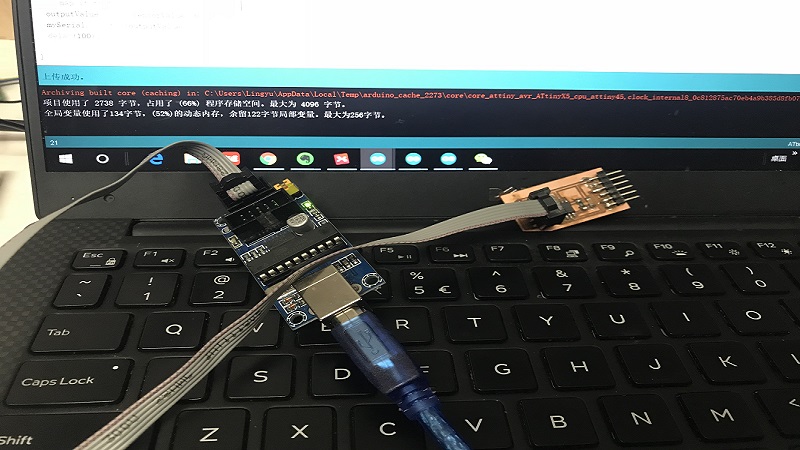
Here's the arduino code.
        #include "SoftwareSerial.h"

        const int analogInPin =  A2;  // Analog input pin that the potentiometer is attached to
        int sensorValue = 0;        // value read from the pot
        int outputValue = 0;        // value output to the PWM (analog out)

        const int Rx = 1; // this is physical pin 7
        const int Tx = 2; // this is physical pin 6
        SoftwareSerial mySerial(Rx, Tx);

        void setup() {
        //  pinMode(3, OUTPUT);
          pinMode(Rx, INPUT);
          pinMode(Tx, OUTPUT);
          mySerial.begin(9600); // send serial data at 9600 bits/sec
        }

        void loop() {
          // read the analog in value:
          sensorValue = analogRead(analogInPin);
          // map it to the range of the analog out:
          outputValue = map(sensorValue, 0, 1023, 0, 255);
          mySerial.println(outputValue);
          delay(100);

        }
And then I code in processing.
       import processing.serial.*;
 Serial myPort;
 int lf = 10;

 void setup(){
   size(300,300);
   myPort = new Serial(this,"/dev/COM8",9600);
 }

 void draw(){
   while(myPort.available() > 0){
     String str = myPort.readStringUntil(lf);
     //println(str);
     if(str!=null){
       int value = Integer.parseInt(trim(str));
       int nValue = (value);
       println(nValue);
       background(nValue);
       if (nValue >127){
         fill(255,0,0);
         rectMode(CENTER);
         rect(150,150,100,100,10,10,10,10);

         textAlign(CENTER, CENTER);
         fill(255);
         textSize(26);
         text("N",150,150);
       }else if(nValue <127){
         fill(0,0,255);
         rectMode(CENTER);
         rect(150,150,100,100,10,10,10,10);

         textAlign(CENTER, CENTER);
         fill(255);
         textSize(26);
         text("s",150,150);
       }else{
         textAlign(CENTER, CENTER);
         fill(255);
         textSize(20);
         text("Where is the magnet? ",150,150);
       }
     }

   }
 }
App Inventor and application.
And then I tried to use App Inventor to make an android app.
First, I use arduino nano, breadboard and neopixel led stripe, uploaded the arduino code wrote by my coworker Zhongtai.
#include#include "Adafruit_NeoPixel.h" #include #define RGB_PIN 8 #define RGB_NUMBER 22 Adafruit_NeoPixel rgbled(RGB_NUMBER); SoftwareSerial mySerial(10, 11); //颜色列表 uint32_t color0 = rgbled.Color(0, 0, 0); //RGB uint32_t color1 = rgbled.Color(255, 0, 0); //RGB 红色 uint32_t color2 = rgbled.Color(255, 70, 0); //RGB 橙色 uint32_t color3 = rgbled.Color(255, 155, 0); //RGB 黄色 uint32_t color4 = rgbled.Color(0, 255, 0); //RGB 绿 uint32_t color5 = rgbled.Color(0, 255, 255); //RGB 青 uint32_t color6 = rgbled.Color(0, 0, 255); //RGB 蓝 uint32_t color7 = rgbled.Color(255, 0, 255); //RGB 紫 uint32_t color_table[] = {color0, color1, color2, color3, color4, color5, color6, color7, color1, color2, color3, color4, color5, color6, color7, color1, color2, color3, color4, color5, color6, color7}; int rgb_value = 0; uint32_t color = rgbled.Color(0, 0, 0); //RGB uint8_t LedCount = 0, cycle = 0, Ycycle = 0, a; void setup() { // put your setup code here, to run once: Serial.begin(9600); mySerial.begin(9600); rgbled.setPin(RGB_PIN); rgbled.begin(); rgbled.setBrightness(50); } int i; String RGB = ""; String R = ""; String G = ""; String B = ""; void do_rgbled() { int SP1 = RGB.indexOf('/'); int SP2 = RGB.indexOf('/', SP1 + 1); int SP3 = RGB.indexOf('/', SP2 + 1); R = RGB.substring(0, SP1); G = RGB.substring(SP1 + 1, SP2); B = RGB.substring(SP2 + 1, SP3); for (int j = 0; j < 22; j++) { rgbled.setPixelColor(j, R.toInt(), G.toInt(), B.toInt()); } rgbled.show(); } bool rainbow_flag; bool spread_flag; bool overall_flag; bool color_flag; void loop() { // put your main code here, to run repeatedly: char ch; while (Serial.available()) { ch = (char)Serial.read(); if (ch != '#') { RGB += ch; } else if (ch == '\r' || ch == '\n') { RGB = ""; } else { if (RGB == "rainbow") { rainbow_flag = 1; spread_flag = 0; overall_flag = 0; color_flag = 0; } else if (RGB == "spread") { spread_flag = 1; rainbow_flag = 0; overall_flag = 0; color_flag = 0; } else if (RGB == "overall") { overall_flag = 1; rainbow_flag = 0; spread_flag = 0; color_flag = 0; } else if (RGB == "color") { color_flag = 1; rainbow_flag = 0; spread_flag = 0; overall_flag = 0; } else { do_rgbled(); rainbow_flag = 0; spread_flag = 0; overall_flag = 0; color_flag = 0; } RGB = ""; } } if (rainbow_flag == 1) { for (Ycycle = 0; Ycycle < 8; rgb_value = Ycycle) { cycle = 0; for (LedCount = 0; LedCount < 22; LedCount++) { color = color_table[rgb_value]; rgbled.setPixelColor(LedCount, color); //在这个函数中i表示的是第几个灯珠进行点亮 if (cycle == 7) { rgb_value = 0; cycle = 0; } rgb_value++; cycle++; } rgbled.show(); //这个函数是对上述的颜色的设置进行一次输出 delay(100); Ycycle++; } } else if (spread_flag == 1) { while (a < 10 + 1) { for (LedCount = 0; LedCount < 22; LedCount++) { if (LedCount == a) rgbled.setPixelColor(LedCount, R.toInt(), G.toInt(), B.toInt()); //在这个函数中i表示的是第几个灯珠进行点亮 else rgbled.setPixelColor(LedCount, 0); } rgbled.show(); //这个函数是对上述的颜色的设置进行一次输出 delay(100); //灯闪烁的频率 a++; //a的自加才是切换灯 } a = 0; } else if (overall_flag == 1) { for (LedCount = 0; LedCount < 22; LedCount++) { rgbled.setPixelColor(LedCount, R.toInt(), G.toInt(), B.toInt()); //在这个函数中i表示的是第几个灯珠进行点亮 } rgbled.show(); //这个函数是对上述的颜色的设置进行一次输出 delay(250); for (LedCount = 0; LedCount < 22; LedCount++) { rgbled.setPixelColor(LedCount, 0); //在这个函数中i表示的是第几个灯珠进行点亮 } rgbled.show(); delay(250); } else if (color_flag == 1) { cycle = 0; color = color_table[rgb_value]; for (LedCount = 0; LedCount < 22; LedCount++) { rgbled.setPixelColor(LedCount, color); //在这个函数中i表示的是第几个灯珠进行点亮 } rgbled.show(); //这个函数是对上述的颜色的设置进行一次输出 delay(250); rgb_value++; cycle++; if (cycle == 7) { rgb_value = 0; cycle = 0; } } }
And then learn to design the app, the app inventor is totally friendly to beginners, it's easy to get started.
.png)
.png)
Zhongtai explained all the process to me step by step and it took me almost 6 hours to understand and finish it.
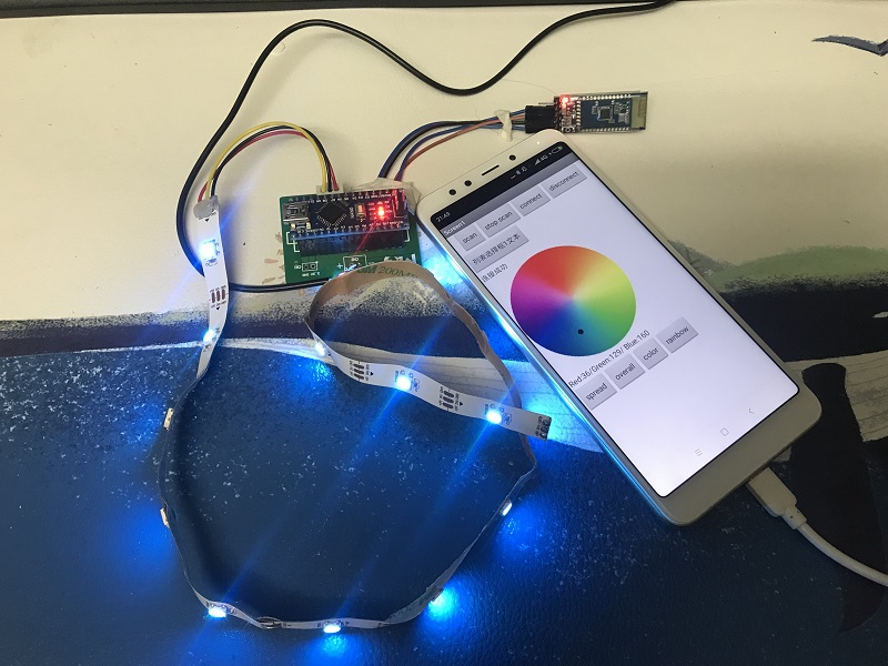
After testing, I use an MG universal board as power supply, solder usb cable and a bluetooth module on the board. And then upload the arduino board wrote by my coworker to the board.
Then, I got this.
Here is the RAR-package files for this week