6. 3D Scanning and printing
This week I worked on an assignment with two parts.
-
Group assignment: Test the design rules for your printer(s).
-
Individual assignment: Design and 3D print an object (small, few cm3, limited by printer time) that could not be made subtractively 3D scan an object (and optionally print it).
Characterization
Advantages and disadvantages of 3D printing
| Advantages | Disadvantages |
|---|---|
| Complexity is free: It actually costs less to print a complex part instead of a simple cube of the same size. The more complex (or, the less solid the object is), the faster and cheaper it can be made through additive manufacturing. | Slow build rates: Many printers lay down material at a speed of 40 to 80 mm/s. Depending on the part needed, other manufacturing processes may be significantly faster. |
| Variety is free: If a part needs to be changed, the change can simply be made on the original CAD file, and the new product can be printed right away. | High production costs: Sometimes, parts can be made faster using techniques other than additive manufacturing, so the extra time can lead to higher costs. Additionally, high-quality additive manufacturing machines can cost anywhere from $300,000 to $1.5 million, and materials can cost $100 to $150 per kg. |
| No assembly required: Moving parts such as hinges and bicycle chains can be printed in metal directly into the product, which can significantly reduce the part numbers. | Considerable effort in application design and setting process parameters: Extensive knowledge of material design and the additive manufacturing machine itself is required to make quality parts. |
| Little lead time: Engineers can create a prototype with a 3D printer immediately after finishing the part’s stereolithography (STL) file. As soon as the part has printed, engineers may then begin testing its properties instead of waiting weeks or months for a prototype or part to come in. | Requires post-processing: The surface finish and dimensional accuracy may be lower quality than other manufacturing methods. |
| Little-skill manufacturing: While complicated parts with specific parameters and high-tech applications ought to be left to the professionals, even children in elementary school have created their own figures using 3D printing processes. | Discontinuous production process: Parts can only be printed one at a time, preventing economics of scale. |
| Few constraints: Anything you can dream up and design in the CAD software, you can create with additive manufacturing. | Limited component size/small build volume: In most cases, polymer products are about 764554858 mm3 in size, while metal parts may only be 28316846.6 mm3. While larger machines are available, they will come at a cost. |
| Less waste: Because only the material that is needed is used, there is very little (if any) material wasted. | Poor mechanical properties: Layering and multiple interfaces can cause defects in the product. |
| Infinite shades of materials: Engineers can program parts to have specific colors in their CAD files, and printers can use materials of any color to print them. |
- 3D Printing
Working with the 3D printer Sindoh 3DWOX DP201 or any Fused Deposition Material technology machine we have to know some main parameters.
-
Temperature (Hotend and heatbed): these values change depending on the material in our case where the Sindoh DP201 is PLA (Polylactic Acid) only the temperature we used was 200 C of Hotend and 0 C of heatbed.
-
Speed (default, travel, outline, etc …): there are many speeds that are involved in 3D printing, but the default speed is the main one, in our case was of 80 mm/s. This speed depends on the quality of the 3D printer, a few 3D printers can handle more than the 60 mm/s, that is considered as a standard in speed.
-
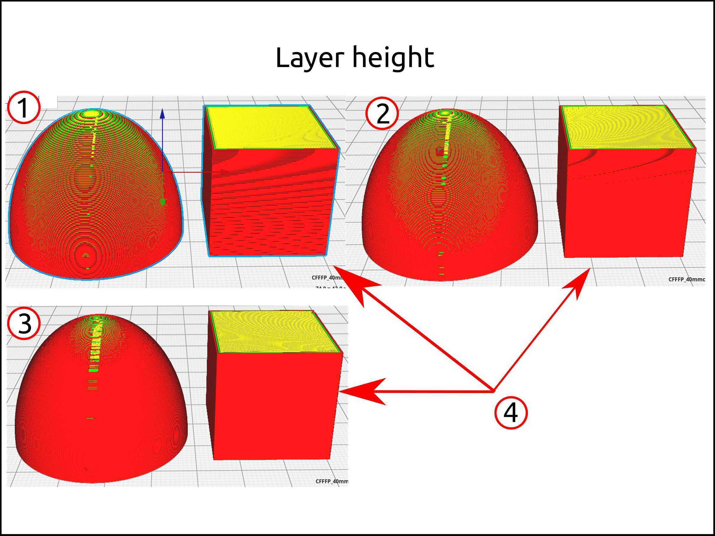
Layer height: for not advance 3D printer operator the slicer software divides into three “qualities”, high, medium and low and these are 0.1 mm, 0.2 mm and 0.3 mm.
The image number 1 is 0.3 mm, the number 2 is 0.2 mm and the number 3 0.1 mm. Here, I am trying to show that layer height really matters in curved surfaces. and for flat surfaces, the layer height is for improves the finishing. The number 4 shows that they look the same for flat surfaces.
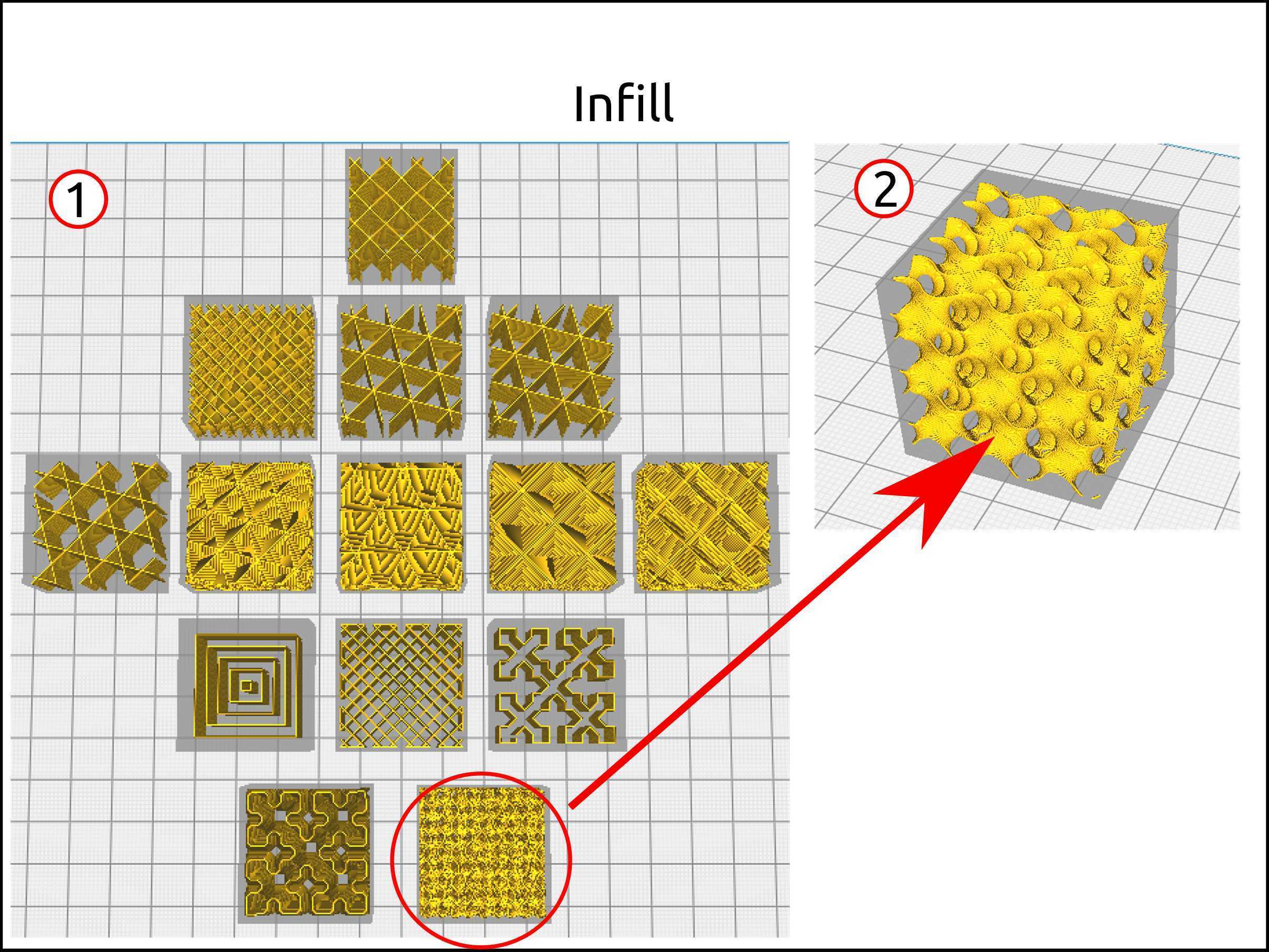
- Infill density and infill pattern: the infill density is that matters all the time but the infill pattern. In number 1, I show you the infill patterns offers by the software Ultimaker Cura.
I used the pattern called Gyroid for the test. This patter is shown in number 2.
This is one of the most beautiful and interesting patterns that were created, because in like the bones pattern, so give us some interesting features like strength and lightweight.
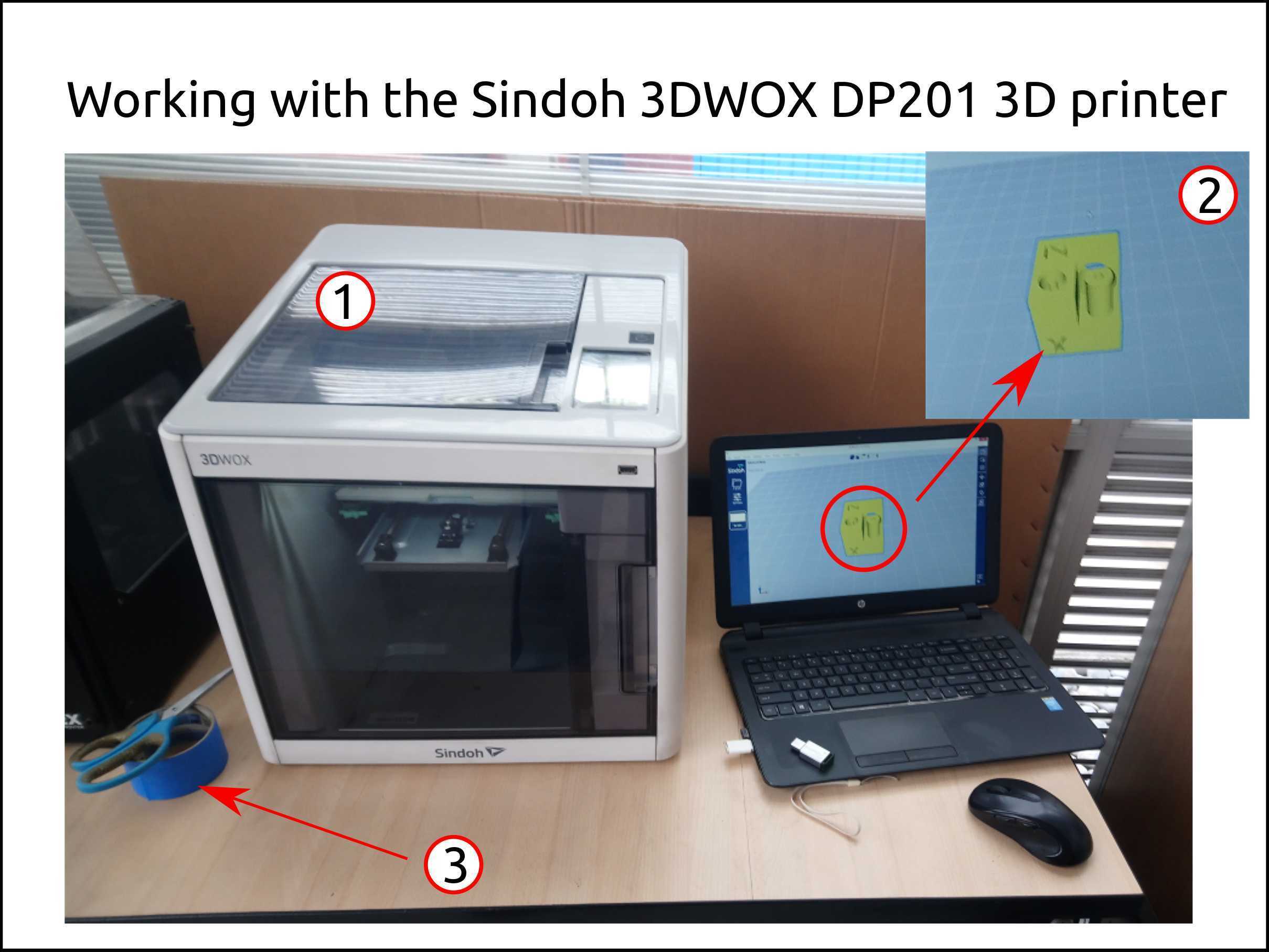
The tools I used was the Sindoh 3DWOX DP201 3D printer (number 1), a laptop and the 3D model itself (number 2) and the masking tape (number 3).
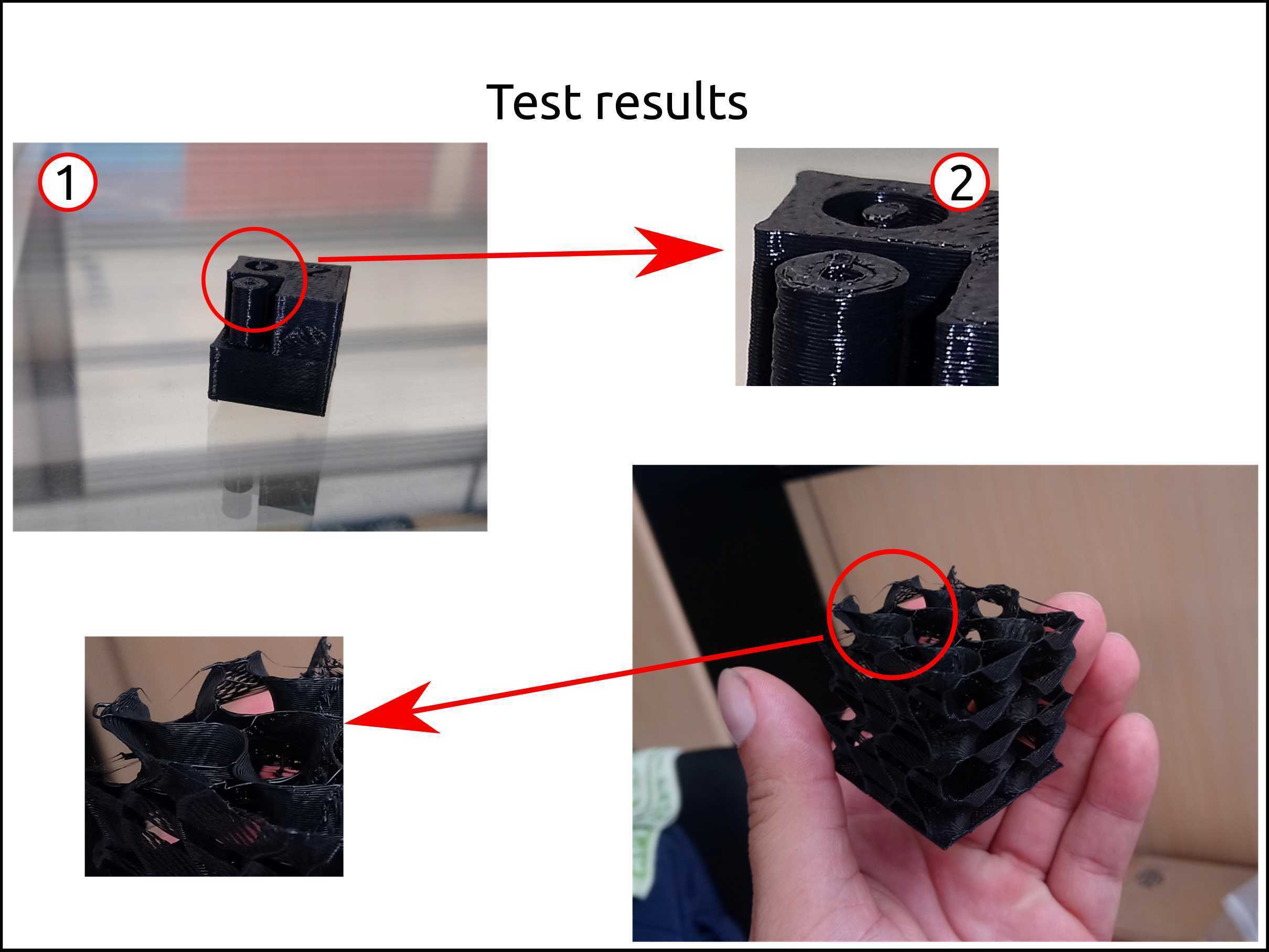
Here I printed two test models:
-
Test cube: here I tried the model (number 1) to know how well works the 3D printer using the Cura slicer and the machine itself. I found the belt was not tight and generate some irregularities in every corner of the model, this is shown in the number 2.
-
Cube: Below the number 1 we have the only infill test, is the cube printer setting the top and wall thickness is zero.
Faced problems and solutions during the 3D scanner characterization
Problems:
-
I tried to generate the gcode for the 3D printer Sindoh 3DWOX DP201 using the software Ultimaker Cura Software V3.6 but was not recognized by the machine besides the extension was the same.
-
After I achieve to print using the software Cura the other problem was that the plastic does not stay on the build plate.
Solution
-
The solution I found was copying the Start Gcode from the code generated by the software called 3DWOX Desktop, and paste in the Cura settings of Start Gcode section.
Start Gcode
;3DWOX Desktop Version : 1.4.2213.0
;[Cartridge_Number] : <0>
;-----------------------------------------

;FILENAME[1/1] VGVzdF9DdWJl

;PRINTER_MODEL: [DP201]
;EMAIL_CHECKCOUNT: [0]
;ESTIMATION_TIME: [0000:30:49]

;DIMENSION: [20:20:20]
;LOCATION: [92:87]
;OPERATINGZONE: [26:26:21]

;CARTRIDGE_COUNT_TOTAL: [1]
;USEDNOZZLE: [1]
;CARTRIDGE_USED_STATE: [T]

;ESTIMATION_FILAMENT_CARTRIDGE_0: [1486]
;MASS_CARTRIDGE_0: [4.4]
;MATERIAL_CARTRIDGE_0: [PLA]

;ESTIMATION_FILAMENT: [1486]
;MASS: [4.4]
;MATERIAL: [PLA]

;TOTAL_MASS: [4.4]
;TOTAL_RAFTLAYER: [4]

T0    ;Raft Cartridge No: [0]

M140 S0        ;Heat up the bed without waiting
M104 T0 S200        ;Heat up the 0th nozzle without waiting

M107    ;fan off
G200    ;nozzle cleaning
G21    ;metric values
G90    ;absolute positioning
G92 E-20    ;zero the extruded length

;M190 S(printer bed temperature)    ;applied from dialog
;M109 S(printer nozzle temperature)    ;applied from dialog

M190 S0        ;Heat up the bed
M109 T0 S200        ;Heat up 0th nozzle nozzle

G28    ;Home
G0 F9000 Z0.20
;Not applied Z offset function
End Gcode
M2;
- The build plate is flexible silicon on the surface and magnets helps it to attach on the metal bed. The fact that is flexible helps to remove the printed piece but in the environment are dust I found that it does not attach on the silicon but using masking tape I solved it.
Advantages and disadvantages of 3D scanning
| Advantages | Disadvantages |
|---|---|
| Applicable to all 2D and 3D surfaces | Some systems do not work in sun or rain |
| Rapid 3D data collection | Large 3D data sets require post-processing to produce a usable output |
| Very effective due to large volumes of data collected at a predictable precision | Difficult in extracting the edges examples from indistinct data cloud |
| Ideal for all 3D modeling and visualization purposes | Output requires manipulation to achieve acceptable recording quality |
| 3D positioning and surface reflectance generated can be viewed as an image | No common data exchange format currently in use |
| Rapidly developing survey technology | Difficulty to stay up-to-date with developments |
| Extensive world-wide research and development currently undertaken | Hardware expensive and sophisticated software required to process data |
- 3D Scanning
There are many kinds of techniques for 3D scanning. We tried 3D scanning using the sensors Kinect and Sense of 3D System. After this, we tried photogrammetry using the software called Meshroom
The parameter that you have to care are:
- Light.
- Object size.
- The 3D scanning method.
- Your computer hardware and operating system.
- The quality you want to get according to your budget.
Faced problems and solutions during the 3D scanner characterization
Problems:
- The Skanect software limit the triangle budget in 5000 triangles, the reduce the quality of the scan.
Solutions:
- Search new software.
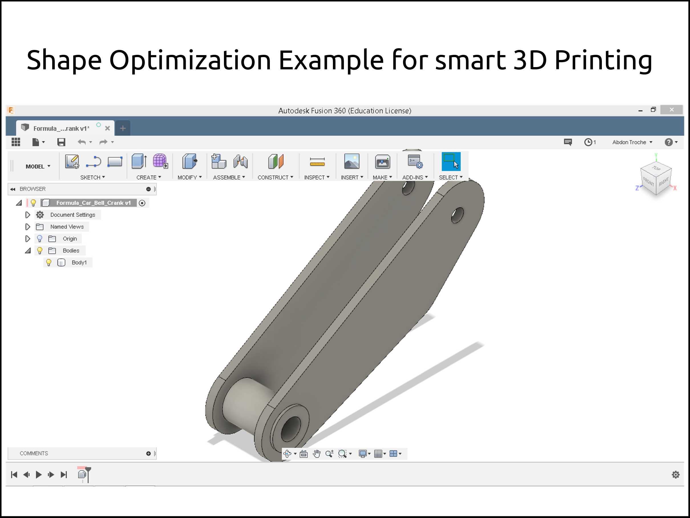
Working with 3d printing
First I imported an existent design, or you could design it, the only thing that matters here is that design has to have the process history.
- Nest you have to select the Simulation module.
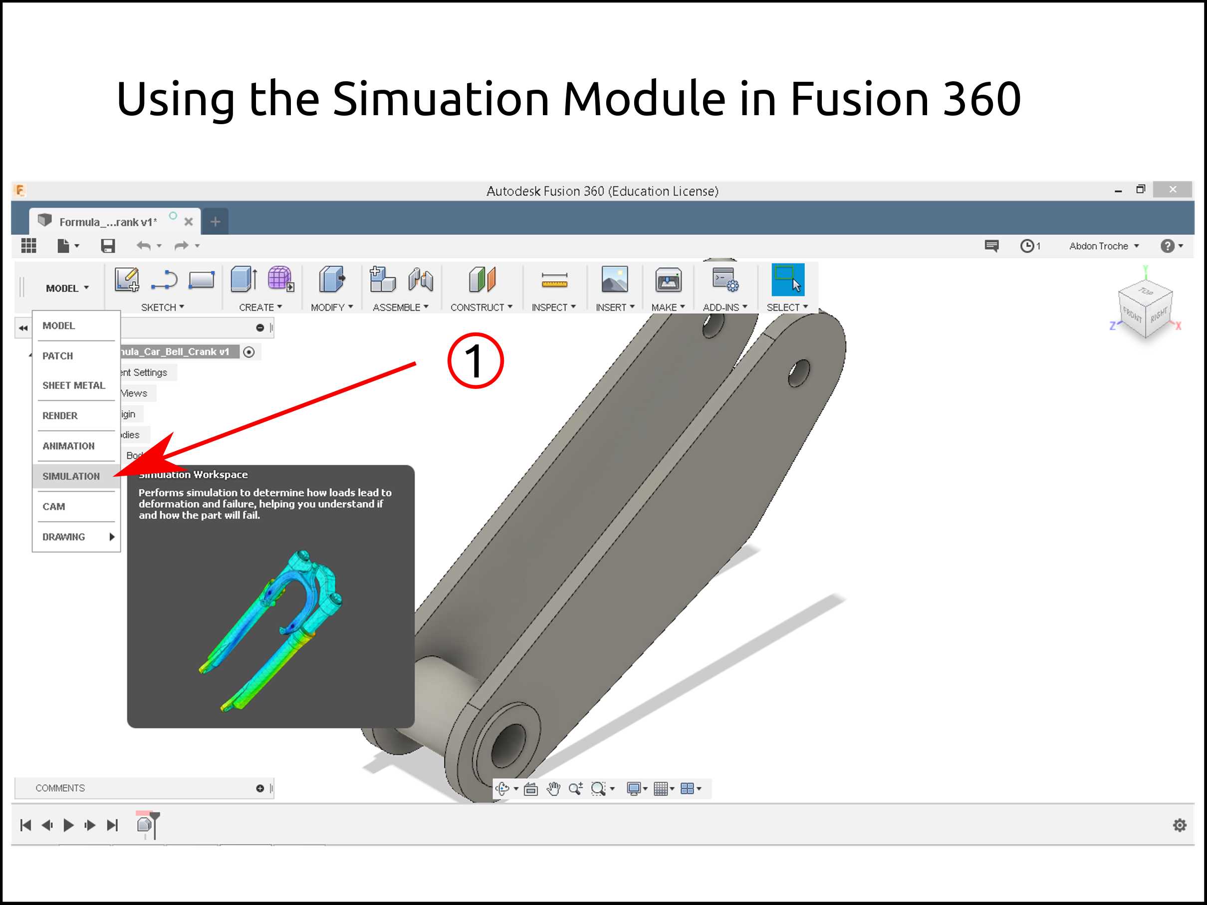
-
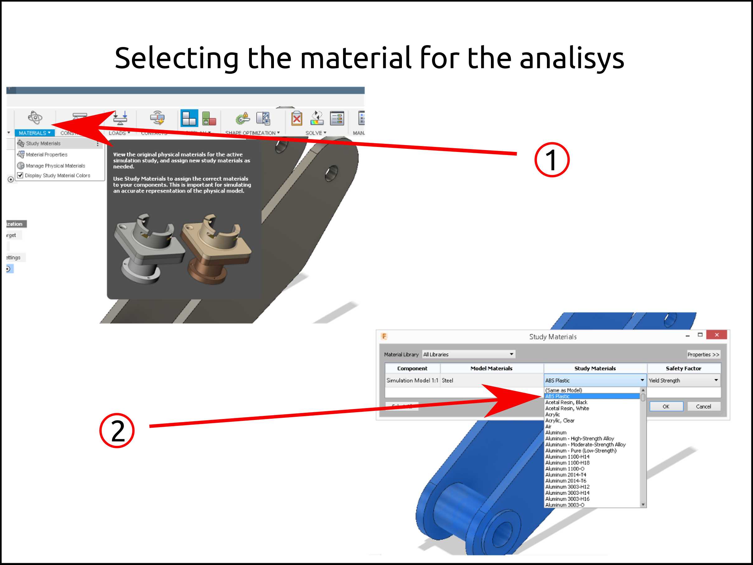
Then select the material icon.
-
Select the material to work with. In my case was ABS.
-
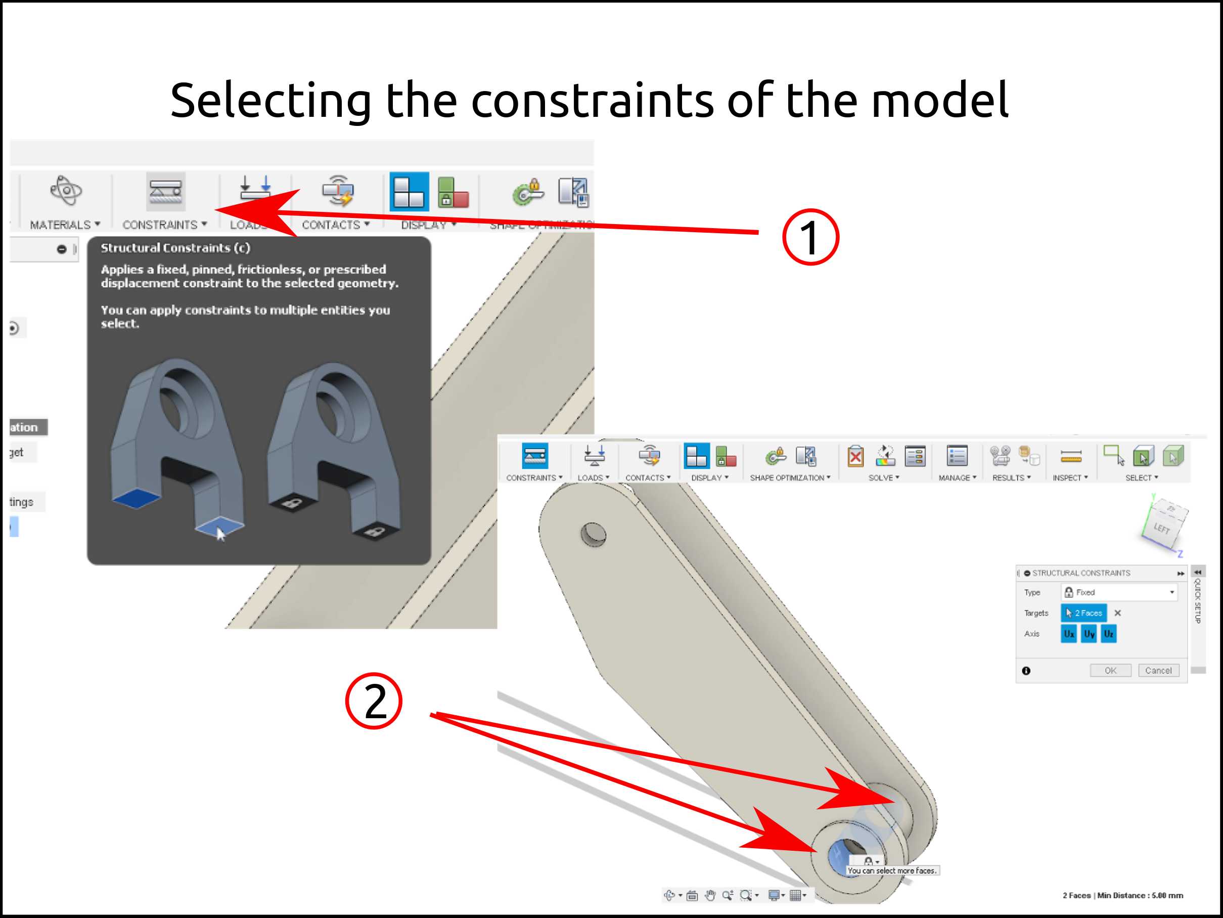
We have to select the constraints of the piece to analyze it.
-
Here is shown the selected constraints.
-
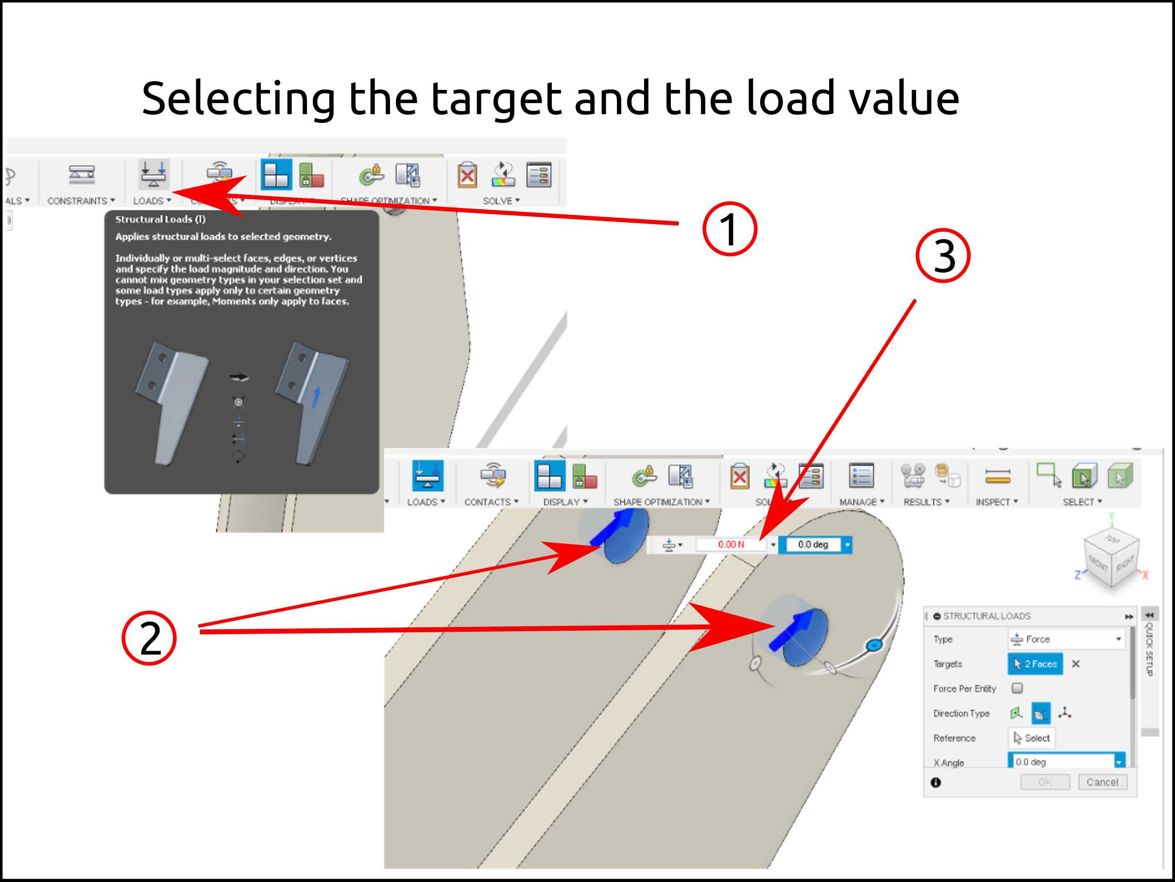
Select the load’s icon.
-
Select the region of the region to put the load, the angle and the amount.
-
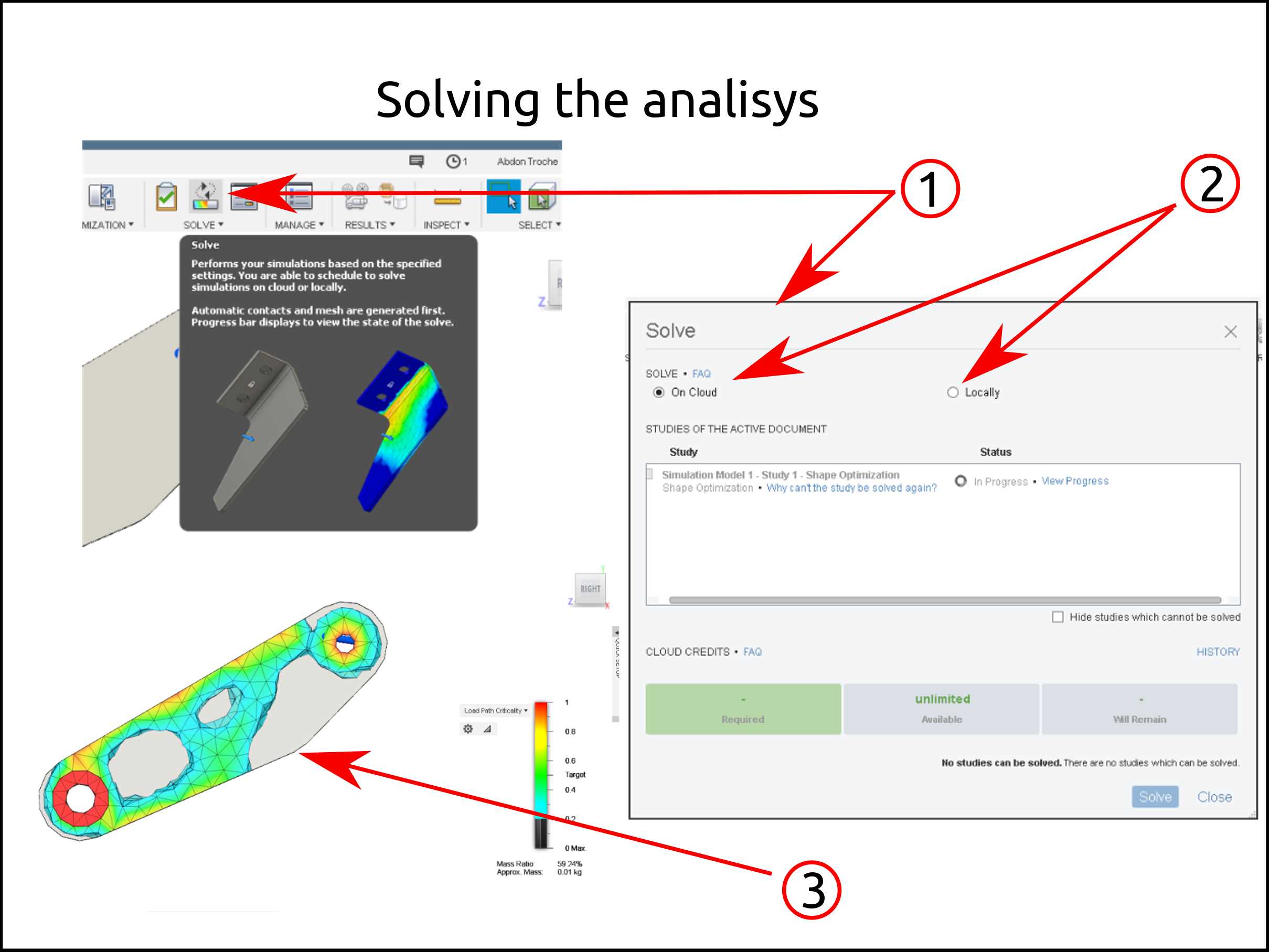
Select the solve icon.
-
You can choose the where to do the analysis of the new object.
-
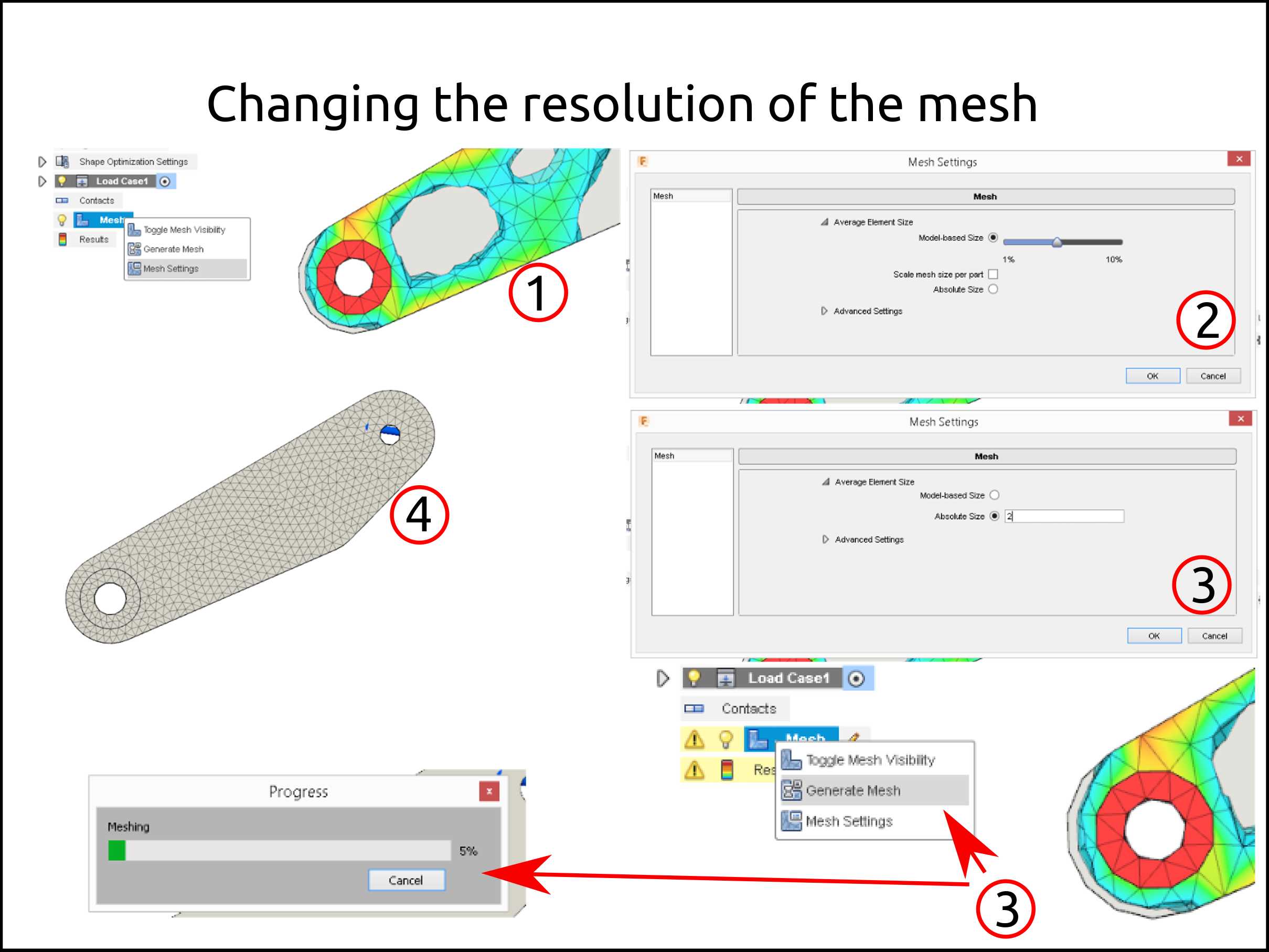
Here show the mesh with triangles.
-
Select the dimension of the triangles you want.
-
Put the value. Using 2 mm of triangle size parameter.
-
Here is shown the optimized mesh triangles.
-
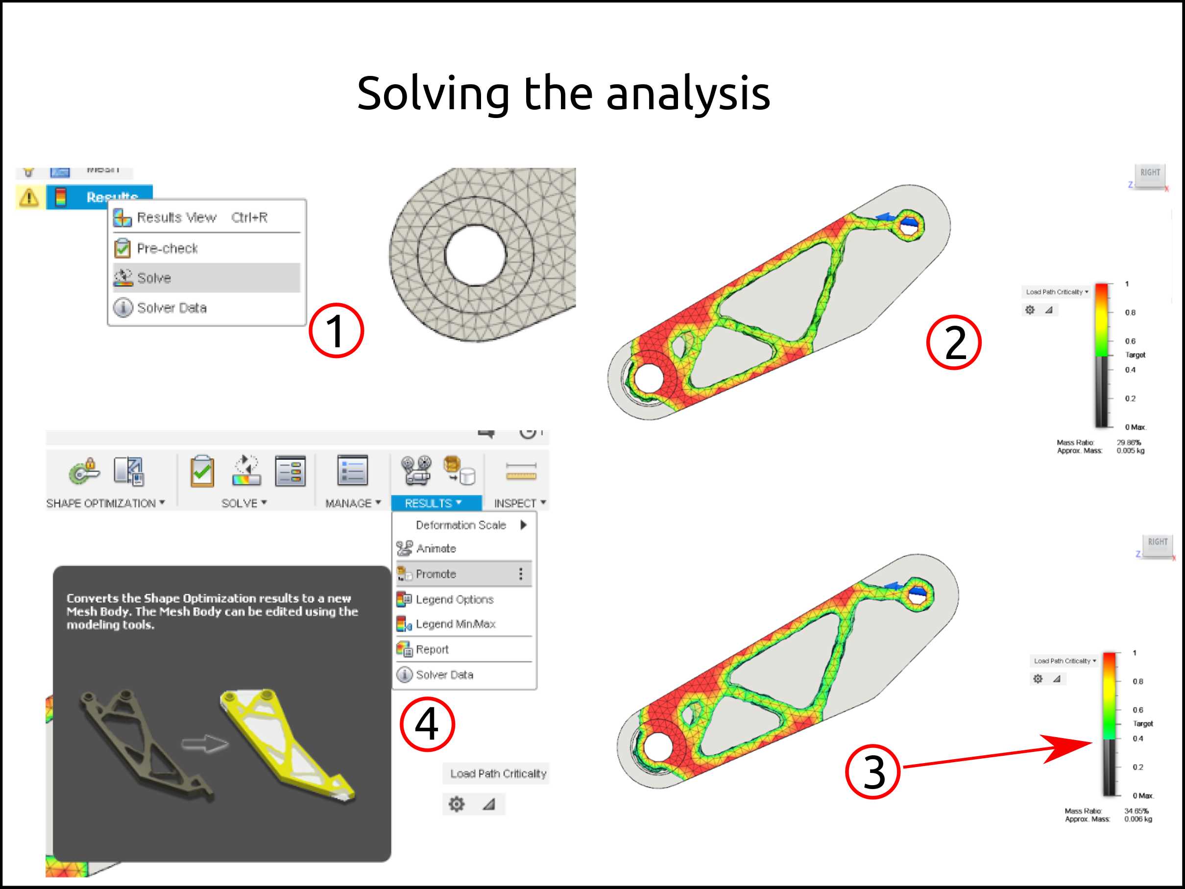
After you refine the mesh you have to resolve the analysis.
-
Inspect the new analysis.
-
Increase the target amount.
-
Finally, put promote to work with the mesh.
-
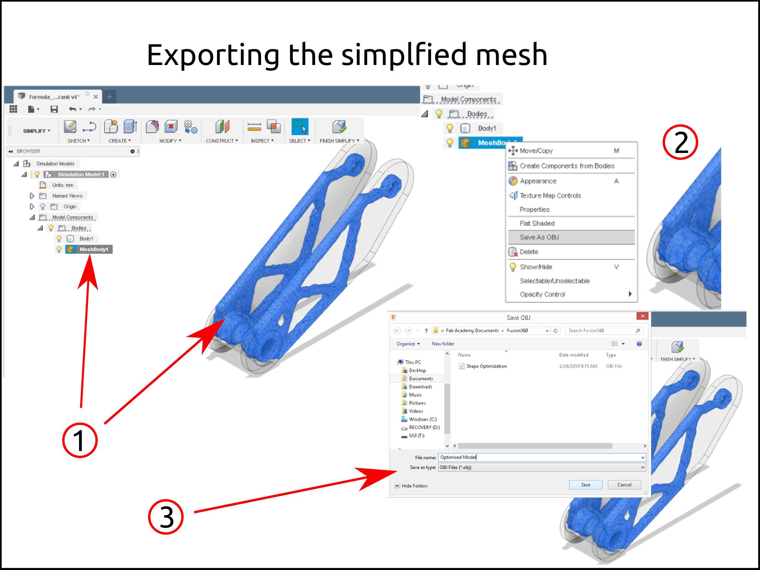
Search the mesh model from the analyze mesh.
-
Choose of saving the mesh.
-
This is the mesh saving place to save.
-
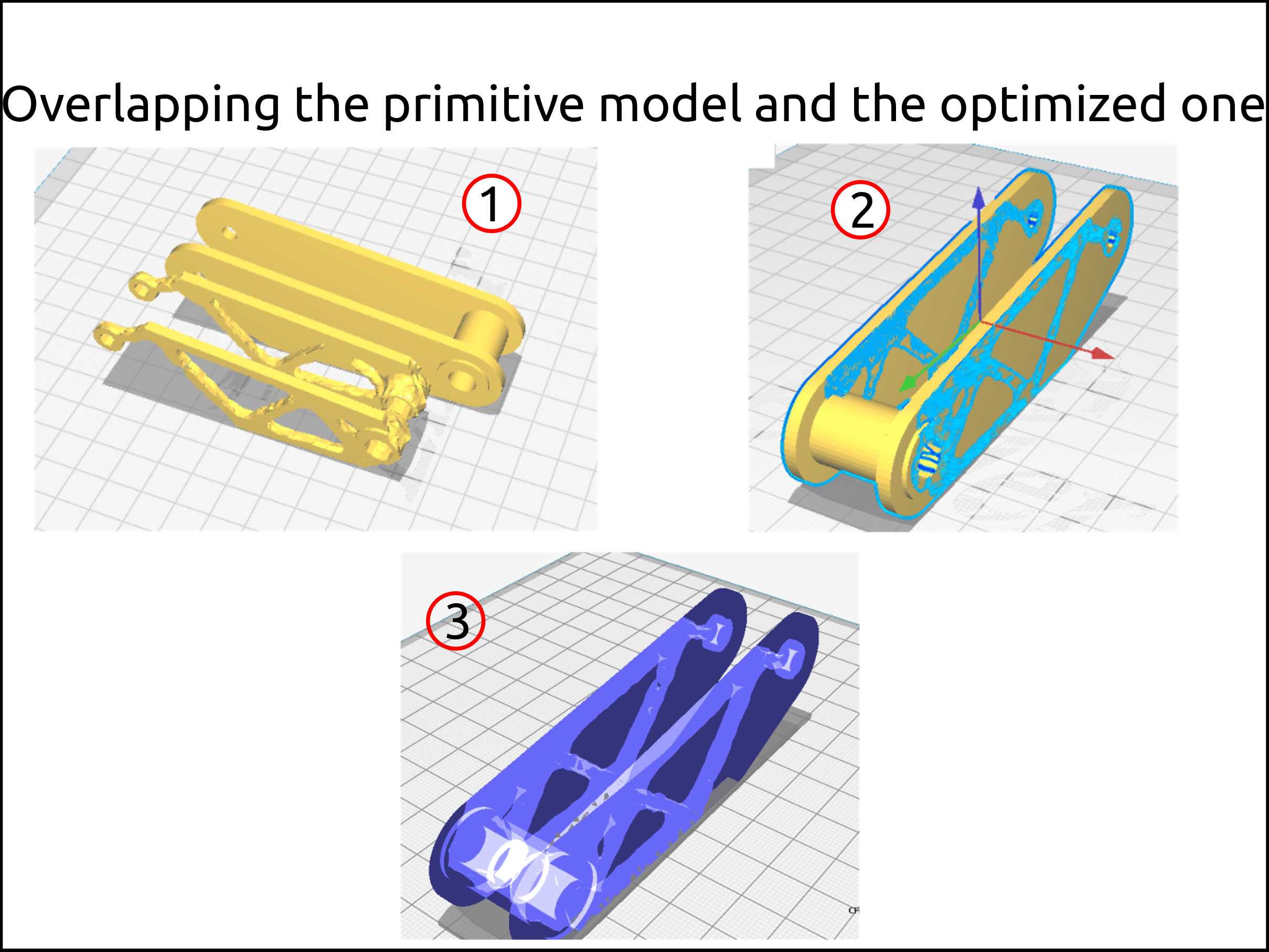
Import both 3d model.
-
Using the environment of Cura, I overlap the models.
-
Here I am showing the x-ray the models to see how they are arranged.
-
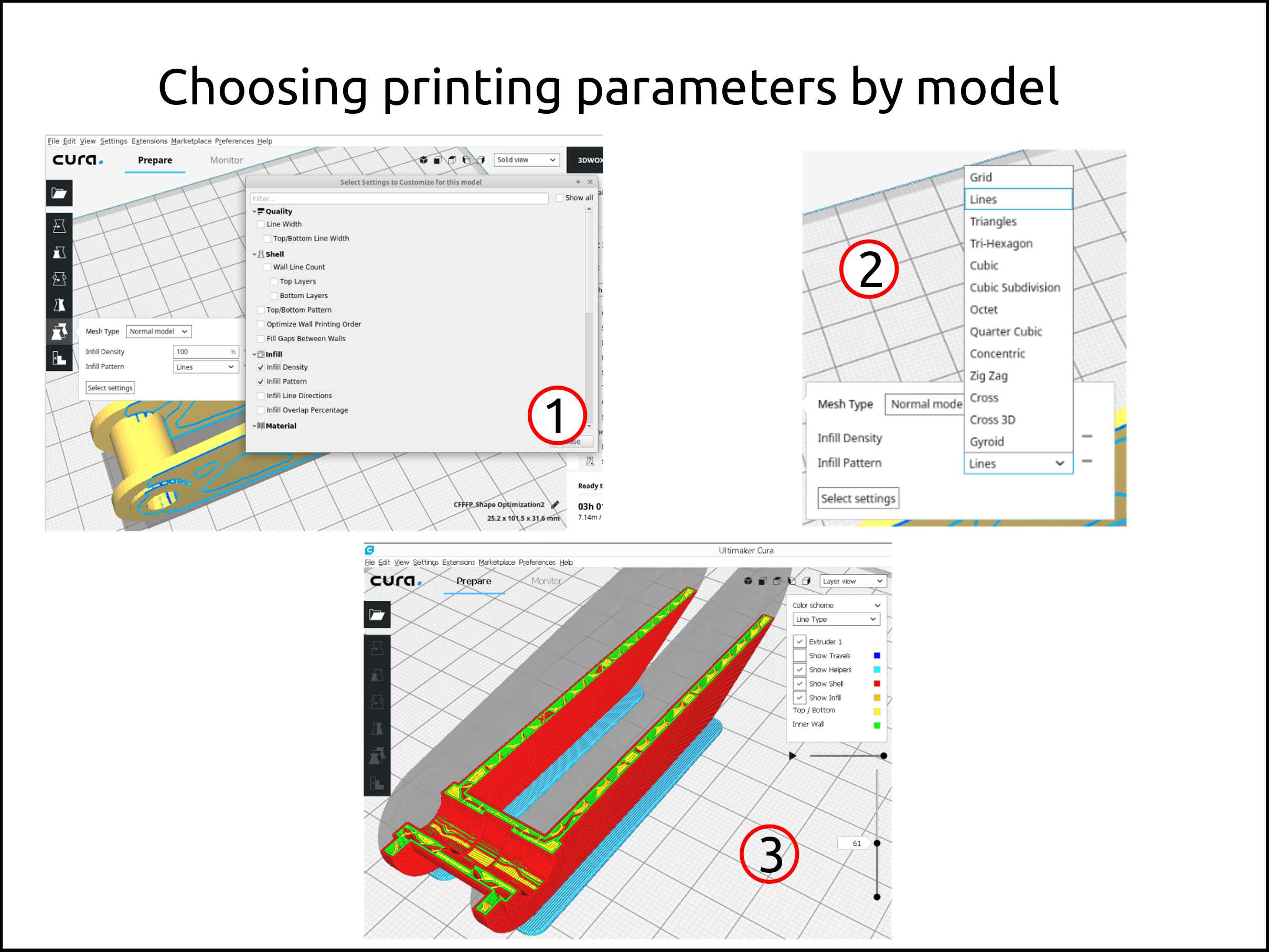
Selecting individual settings for each 3d model.
-
Selecting the infill pattern.
-
Generate the Gcode.
Faced problems and solutions working with the 3D printer
Problems:
-
The 3D printed part was so shiny.
-
The edges of the printed part that are parallel with the Z-axis are not well defined, in other words, are rounded.
Solutions:
-
Reduce the hotend temperature from 200 C to 190 C.
-
These problems occur because two main things, first the X/Y axis are not well adjusted, second the Jerk value is too high, in my case was only the belt.
Files of 3D printing
-
Cura Slicer v 3.6 project for Sindoh 3DWOX machine profile
- By opening this file in your Cura software all the settings and profiles will be added to your software. In other words, you are able to use the new settings to generate gcode for a new model after.
Why this 3d model can not be made subtractively?
This model can not be made subtractively because the 3D model is not fully solid,in other words, has 100% of material where the part requires because the stress that it will be influenced by.
Nowadays is used the generative manufacturing in order to save material, so that means the the 3D model it needs to be hollow or with low infill where it is not required.
I made a simple 3D design just because I wanted to try the generative improvement, so this method can be used to produce a more complex model that will add a geometry restriction to the model that subtractive can be produced by.
Working with 3d scanning
3D Scanning with Sensors
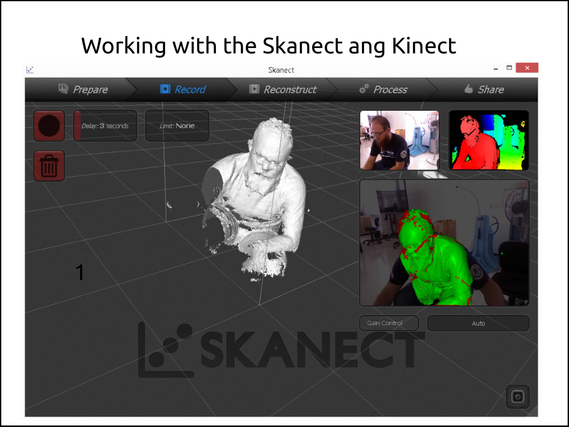
3D scanning using the software Skanect free version
With Skanect, capturing a full-color 3D model of an object, a person or a room has never been so easy and affordable. Skanect transforms your Structure Sensor, Microsoft Kinect or Asus Xtion camera into a low-cost 3D scanner able to create 3D meshes out of real scenes.
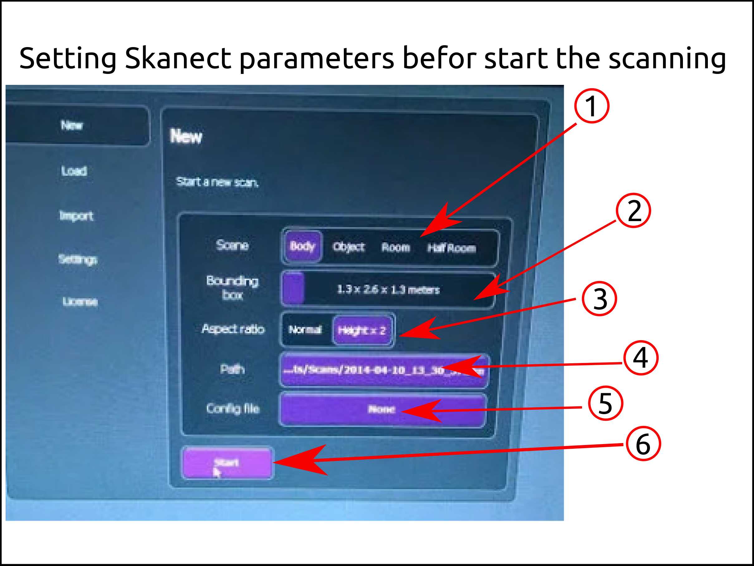
-
Here you select the “scene” depending on your object size.
-
Here the software shows you your working space.
-
Here you can change the aspect ratio as you need it.
-
Here you select where you want to save your scanned model after the scanning process.
-
Generally, this setting is by default.
-
After setting all the parameters above you click here to start scanning.
Here I show me scanning myself using the Kinect and Skanect.
-
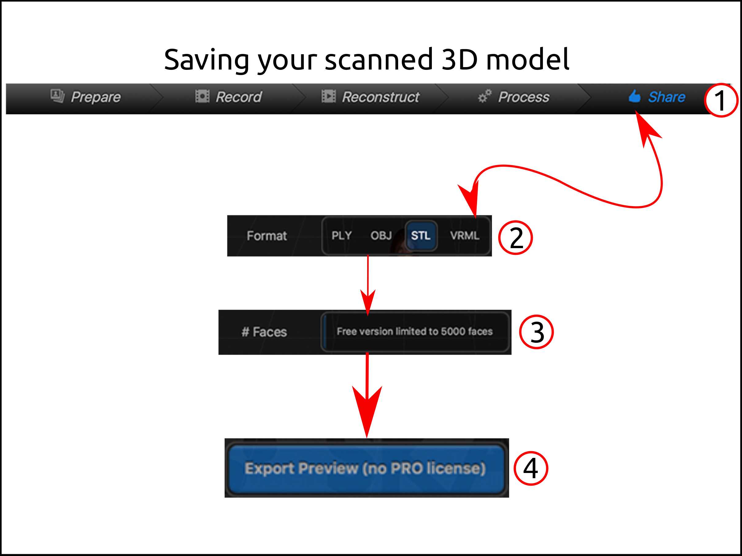
To save your scanned model you have click on share.
-
Depending on what technology you want to 3D print you select the output format, for example, you want to preserve the texture (colors) PLY and OBJ are the right formats, otherwise STL is enough.
-
Skanect is proprietary software so its limitation in the free version is the quantity of the triangles (5000). That means that only works for big objects in the free version to maintain the quality.
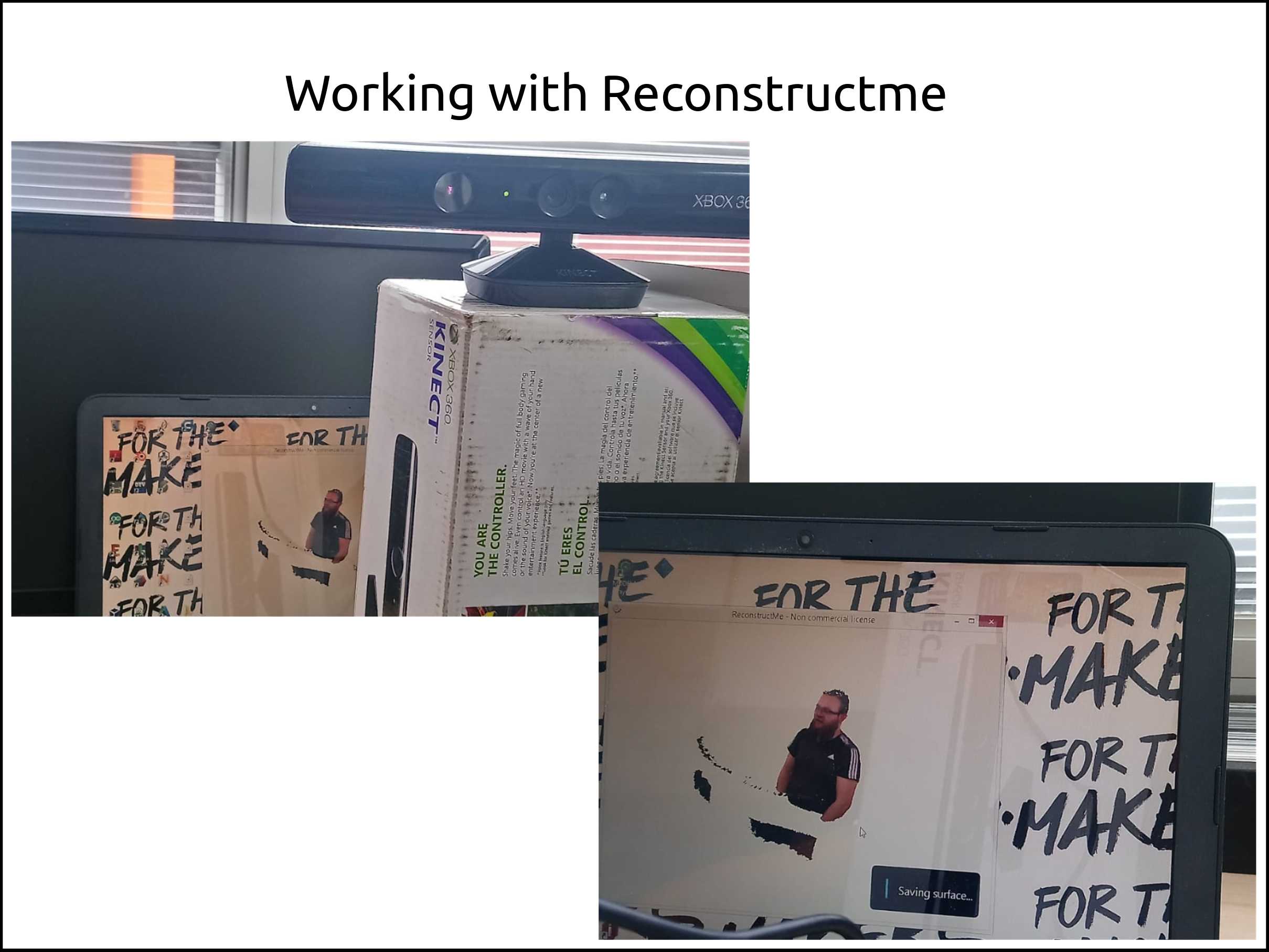
3D scanning using the software Reconstructme
ReconstructMe’s usage concept is similar to that of an ordinary video camera – simply move around the object to be modeled in 3D. Scanning with ReconstructMe scales from smaller objects such as human faces up to entire rooms and runs on commodity computer hardware. Read more about its features. Integrate ReconstructMe into your application using our powerful SDK.
I scanned myself using the Kinect and Reconstrucme to see its performance.
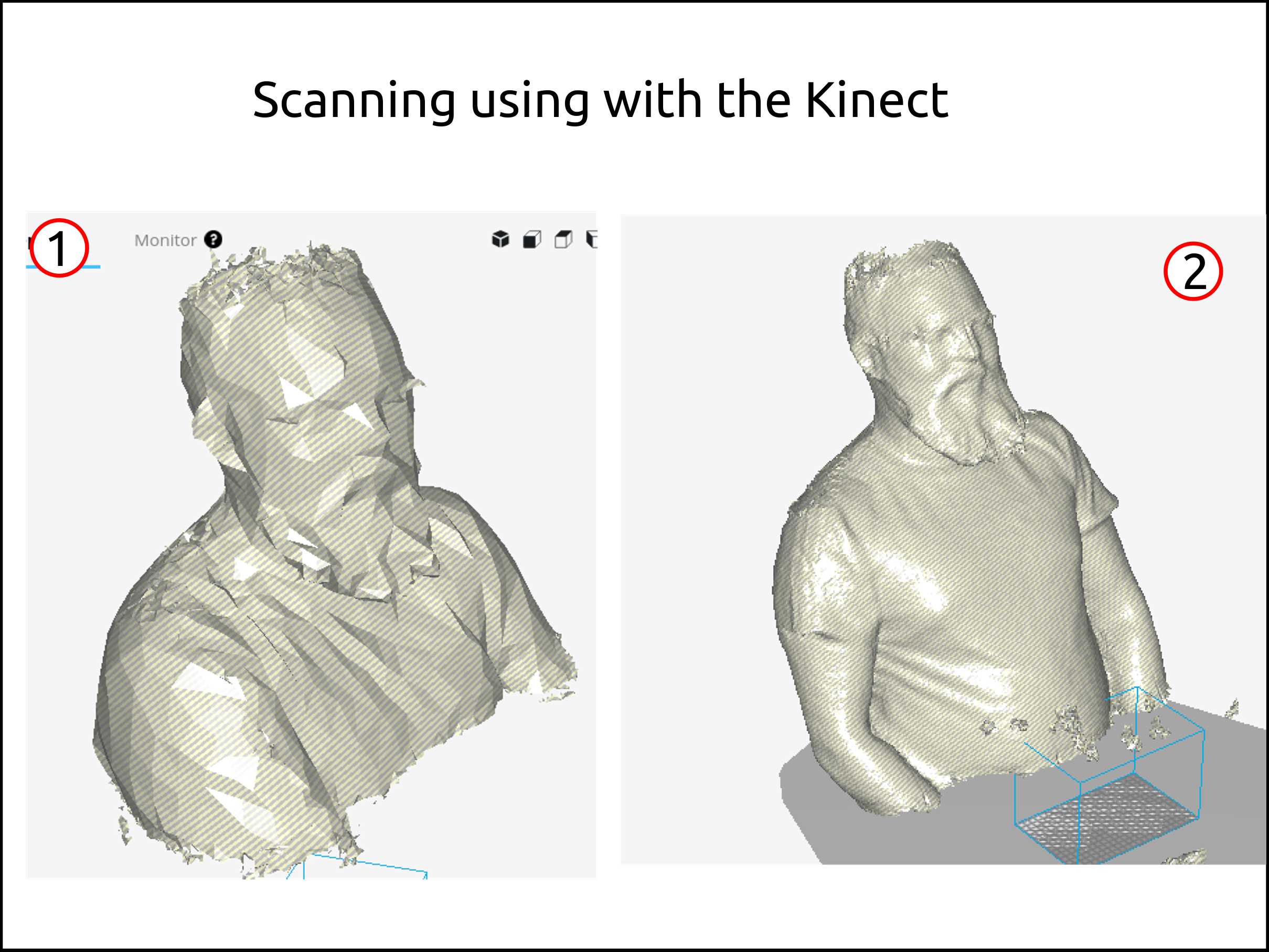
Both Skanect and ReconstructMe were a free version and the difference was huge.
-
Using the software skanect I got a low poly scanned model limited by the 5000 triangle budget.
-
The software Reconstructme was an interesting discovery. Besides was freemium I got a good result.
Faced problems and solutions working with the 3D scanner using Meshroom
Problems:
-
The Skanect limitation of 5000 polygons does not allow me to scan small objects.
-
To work with the sensor even Skanect or Reconstructme you have to run Microsoft Windows as an Operate System.
Solutions:
-
I researched a new software and I found one called Reconstructme, and this works incredibly well with fewer problems.
-
The solution can be just run a Windows in VirtualBox or make your machine dual boot, saying differently, install Linux OS and Windows OS in the same machine partitioning you Hard Disk Drive.
Files from the 3D scanning using sensors
3D Scanning with Photogrametry
Meshroom photogrametry software
Meshroom is a free, open-source 3D Reconstruction Software based on the AliceVision framework.
This software requires an NVIDIA CUDA-enabled GPU
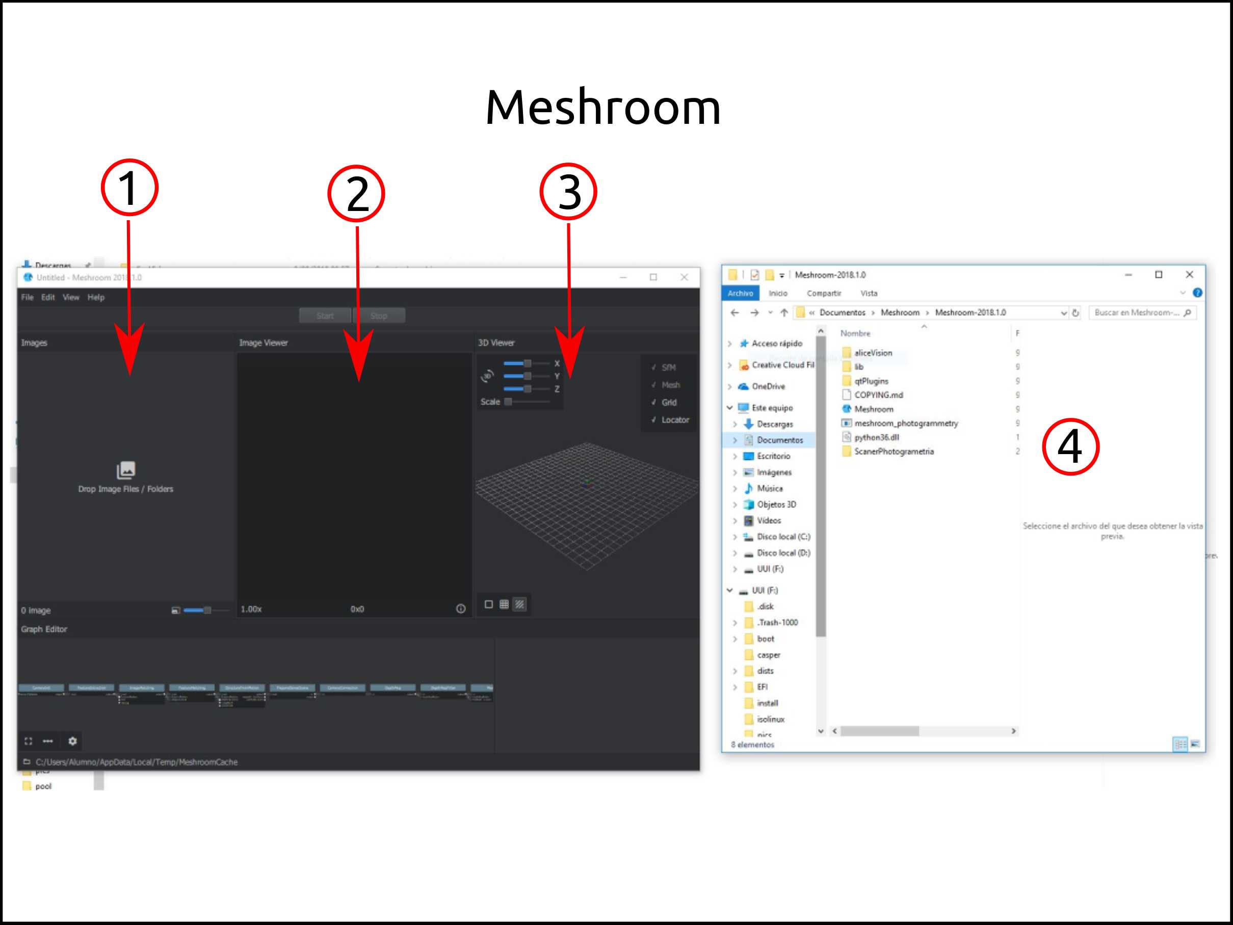
- Here you have to drag and drop your images.
- I order to obtain many images I tried recording a video of the object and the use ffmpeg to separate them in frames.
To convert video to png images you need to run this command:
ffmpeg -ss 00:10 -i video-filename.mp4 -t 00:03 images-filename_%03d.png
where:
-
-ss defines the offset from the beginning of the video.
-
-t specifies how long the fragment should be.
-
-i is to provide the input video file name.
-
%03d - indicated to use 3 digits number.
For example, the output will be like this:
- images-filename_001d.png
- images-filename_002d.png
- images-filename_003d.png
2.Here preview each image if you want to check them.
3.Here the software shows you how the 3D object is generating.
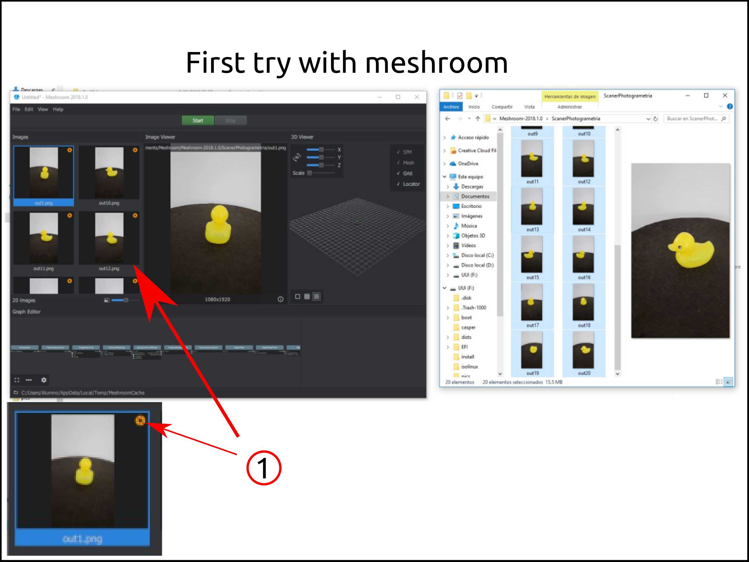
4.Your images have to be in one place to select them at the same time.
- This icon is shown when the software cannot match your images.
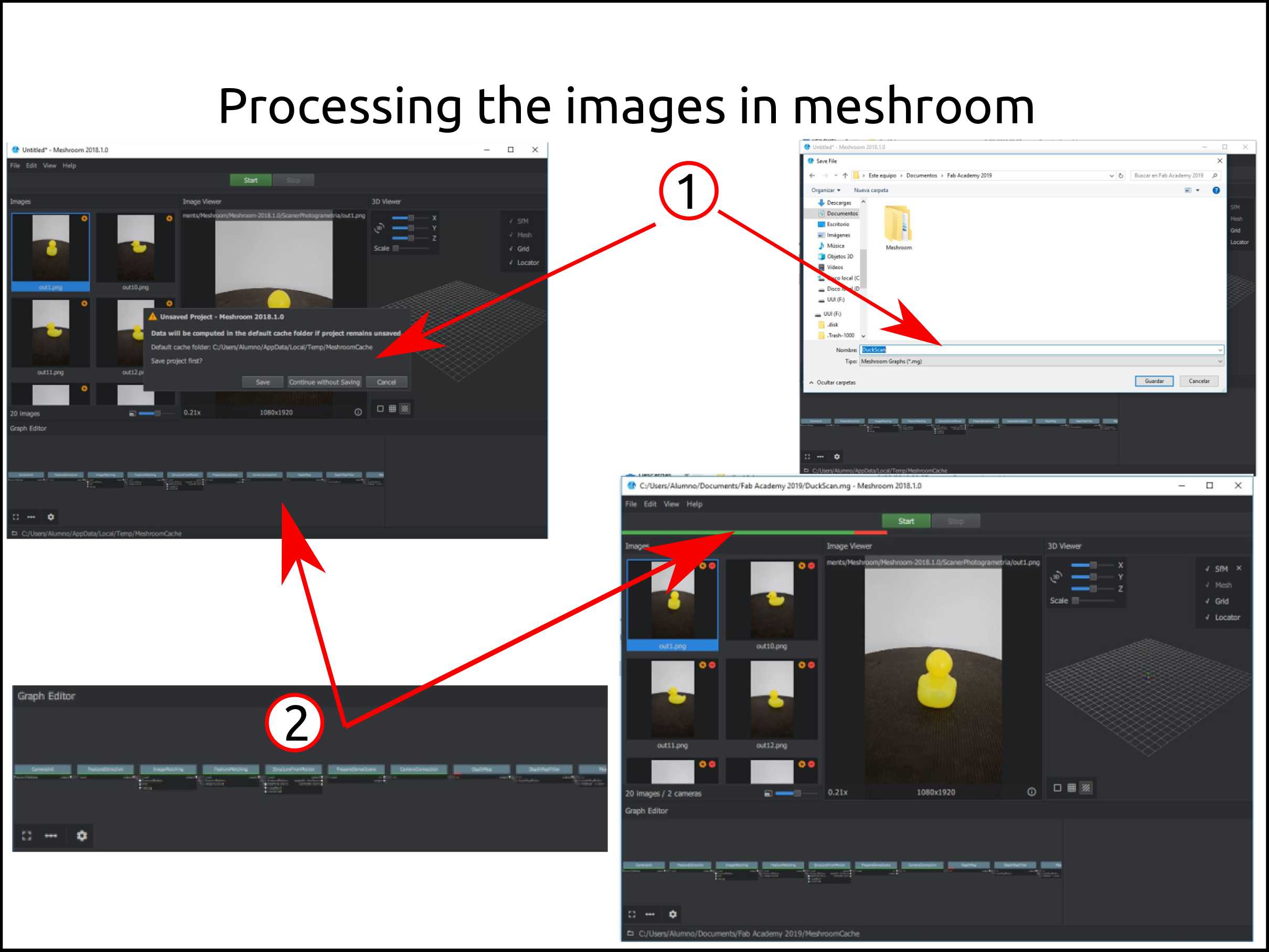
-
Before starting the processes we have to save the project.
-
Here you can see the processes bar and the algorithms that will be applied to your images
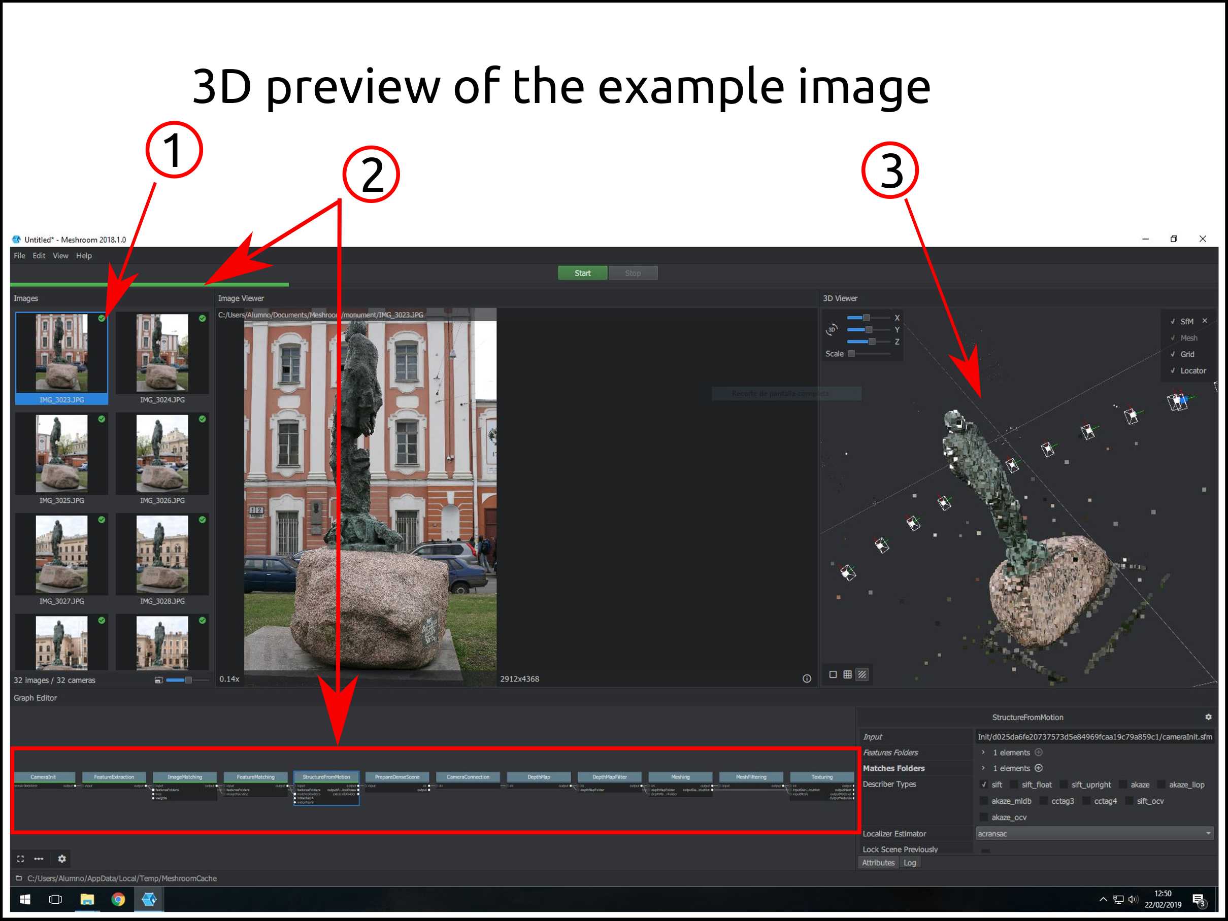
Because I made a mistake taking the right photos I decided to use a set of pictures from the web with the purpose of trying the software Meshroom.
For this example, I used the images from this site.
-
This is the icon for a matched picture.
-
These are the progress bar and the algorithms that correspond to them.
-
Here is the preview of the scanned object, and this you can do to check in what part of the object needs more pictures in order to add them.
Faced problems and solutions working with the 3D scanner using Meshroom
Problems:
- It did not work in my laptop because of the hardware limitation.
Solutions:
- I used the Fab Lab PC to try it.
Files used in Meshroom and files gotten from Meshroom
What I learned this week?
I learned how to use the Software called OBS Studio (https://obsproject.com/), that is used to broadcasting your screen or just record it.
I learned how to use the simulation module in F360 to do smart infill. These technics I used for my 3d printing task.
There is more software out there that I tried to use or install and I failed in the process. They were: - COLMAP * Related video - OrtogOnBlender * Related video