11. Input devices
-
Group assignment: Measure the analog levels and digital signals in an input device
-
Individual assignment: Measure something: add a sensor to a microcontroller board that you have designed and read it.
Hello Button circuit
Components of the hello button circuit and board.
| Component | SMD Code | Quantity |
|---|---|---|
| ATtiny45 or ATtiny85 | TINY45 or TINY85 | 1 |
| 10kΩ resistor | 1002 | 1 |
| 1x6 pin header male | NONE | 1 |
| Button | NONE | 1 |
| 1uF capacitor | NONE | 1 |
| 2x3 pin header | NONE | 1 |
The code for the hello Button
For the Hello Button i used the example code given by Neil.
//
//
// hello.button.45.c
//
// button hello-world
//    9600 baud FTDI interface
//
// Neil Gershenfeld
// 10/31/10
//
// (c) Massachusetts Institute of Technology 2010
// This work may be reproduced, modified, distributed,
// performed, and displayed for any purpose. Copyright is
// retained and must be preserved. The work is provided
// as is; no warranty is provided, and users accept all
// liability.
//

#include <avr/io.h>
#include <util/delay.h>

#define output(directions,pin) (directions |= pin) // set port direction for output
#define input(directions,pin) (directions &= (~pin)) // set port direction for input
#define set(port,pin) (port |= pin) // set port pin
#define clear(port,pin) (port &= (~pin)) // clear port pin
#define pin_test(pins,pin) (pins & pin) // test for port pin
#define bit_test(byte,bit) (byte & (1 << bit)) // test for bit set
#define bit_delay_time 102 // bit delay for 9600 with overhead
#define bit_delay() _delay_us(bit_delay_time) // RS232 bit delay
#define half_bit_delay() _delay_us(bit_delay_time/2) // RS232 half bit delay

#define input_port PORTB
#define input_direction DDRB
#define input_pin (1 << PB4)
#define input_pins PINB
#define serial_port PORTB
#define serial_direction DDRB
#define serial_pin_out (1 << PB2)

void put_char(volatile unsigned char *port, unsigned char pin, char txchar) {
   //
   // send character in txchar on port pin
   //    assumes line driver (inverts bits)
   //
   // start bit
   //
   clear(*port,pin);
   bit_delay();
   //
   // unrolled loop to write data bits
   //
   if bit_test(txchar,0)
      set(*port,pin);
   else
      clear(*port,pin);
   bit_delay();
   if bit_test(txchar,1)
      set(*port,pin);
   else
      clear(*port,pin);
   bit_delay();
   if bit_test(txchar,2)
      set(*port,pin);
   else
      clear(*port,pin);
   bit_delay();
   if bit_test(txchar,3)
      set(*port,pin);
   else
      clear(*port,pin);
   bit_delay();
   if bit_test(txchar,4)
      set(*port,pin);
   else
      clear(*port,pin);
   bit_delay();
   if bit_test(txchar,5)
      set(*port,pin);
   else
      clear(*port,pin);
   bit_delay();
   if bit_test(txchar,6)
      set(*port,pin);
   else
      clear(*port,pin);
   bit_delay();
   if bit_test(txchar,7)
      set(*port,pin);
   else
      clear(*port,pin);
   bit_delay();
   //
   // stop bit
   //
   set(*port,pin);
   bit_delay();
   //
   // char delay
   //
   bit_delay();
   }

int main(void) {
   //
   // main
   //
   // set clock divider to /1
   //
   CLKPR = (1 << CLKPCE);
   CLKPR = (0 << CLKPS3) | (0 << CLKPS2) | (0 << CLKPS1) | (0 << CLKPS0);
   //
   // initialize pins
   //
   set(serial_port, serial_pin_out);
   output(serial_direction, serial_pin_out);
   set(input_port, input_pin); // turn on pull-up
   input(input_direction, input_pin);
   //
   // main loop
   //
   while (1) {
      //
      // wait for button down
      //
      while (0 != pin_test(input_pins,input_pin))
         ;
      put_char(&serial_port, serial_pin_out, 'd');
      //
      // wait for button up
      //
      while (0 == pin_test(input_pins,input_pin))
         ;
      put_char(&serial_port, serial_pin_out, 'u');
      }
   }
-
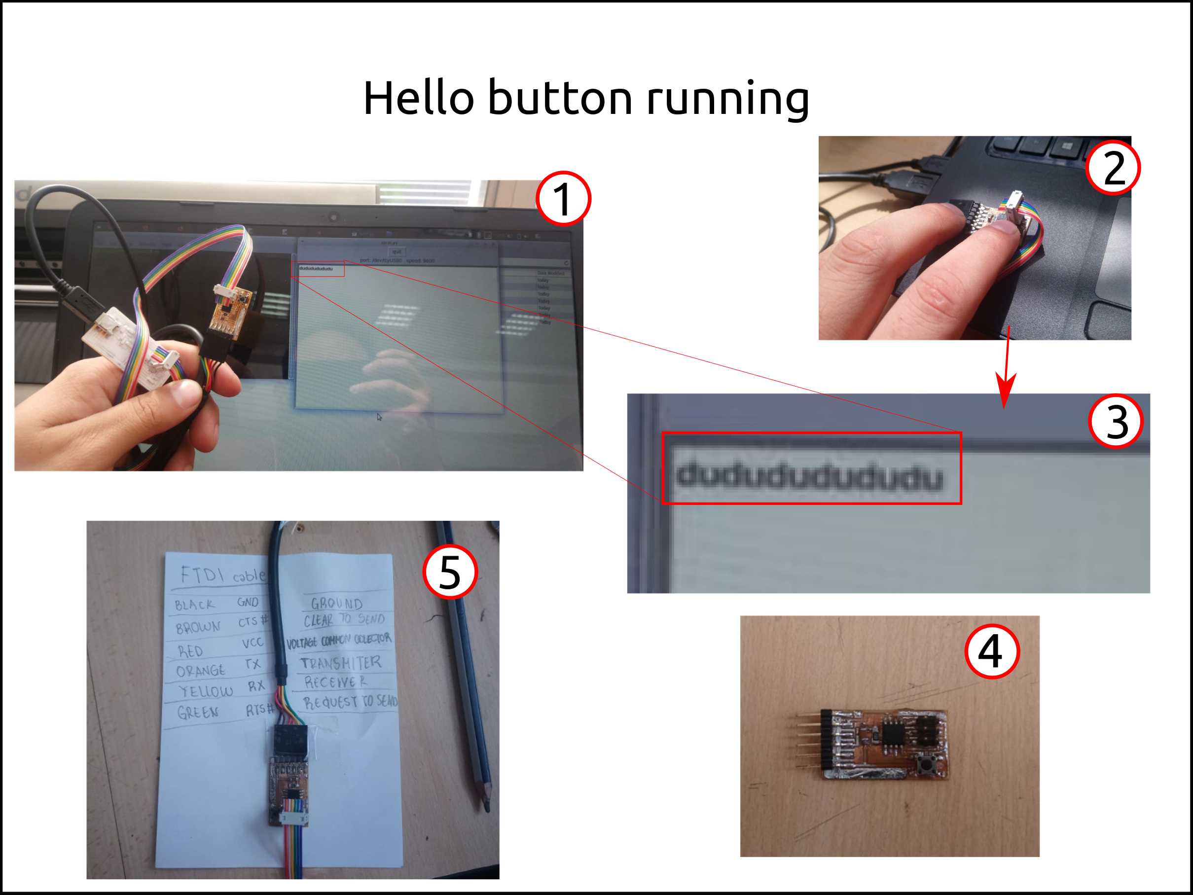
Here I show what I used and I worked with the Hello Button board. I used my ISP programmer with based on the attiny44 and the FTDI cable.
-
Here I am showing the moment where I pressed the button to send a signal to through the serial communication to the laptop.
-
The program inside the chip detect the changes of states on the input what is connected the button. So, Here we see the messages that the machine read.
-
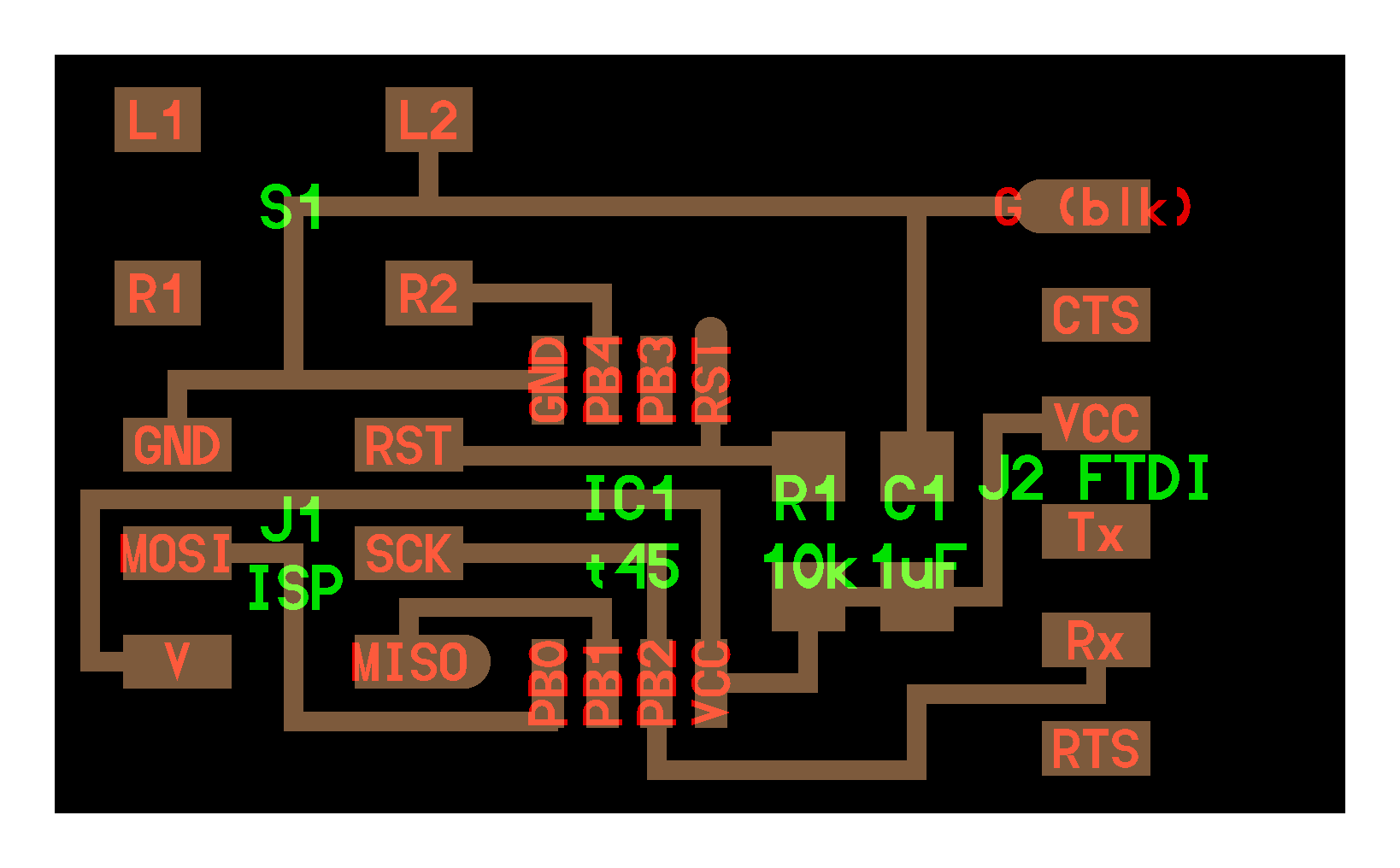
Here we have the hello button board, that has a ISP connection to program the board and the FTDI connection as well, in order to perform the communication.
-
Here wee see what is each pin of the FTDI.
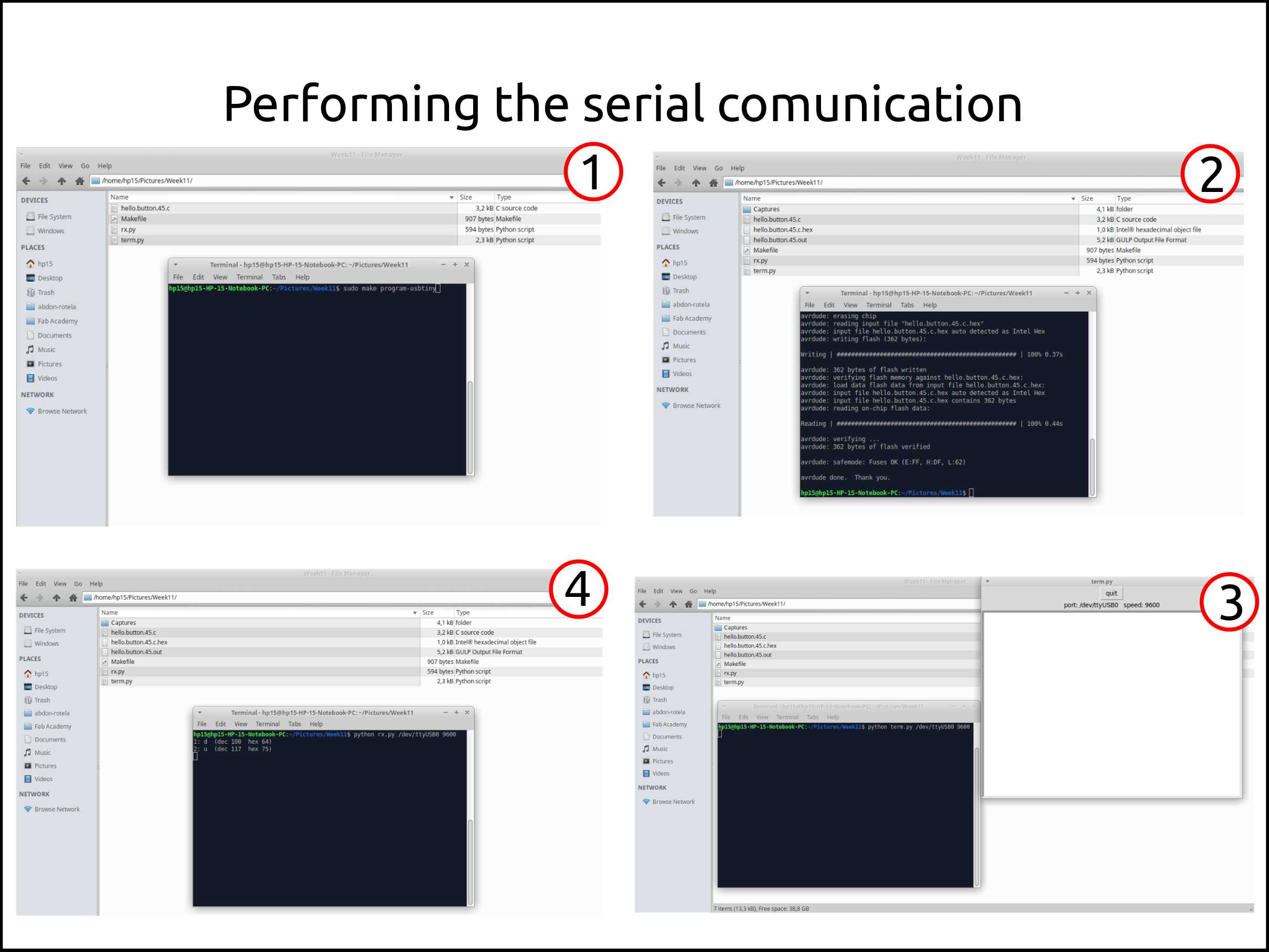
- This is the command that I used in to load the program. I thing that is very important to remember is that the Makefile content all the command you could use.
sudo make program-usbtiny
-
Here we see that the program was loaded successfully.
-
In this case the data is read using a python script with an interface using Tkinter.
-
Here we see the messages from the board to the machine using the terminal. To do this is necessary a shot python code.
1 2 3 4 5 6 7 8 9 10 11 12 13 14 15 16 17 18 19 20 21 22 23 24 25 26 27 28 29 30 | #!/usr/bin/env python # # rx.py # # rx.py serial_port port_speed # # Neil Gershenfeld # CBA MIT 7/27/07 # # (c) Massachusetts Institute of Technology 2007 # Permission granted for experimental and personal use; # license for commercial sale available from MIT. # import serial, sys if (len(sys.argv) != 3): print "command line: rx.py serial_port port_speed" sys.exit() port = sys.argv[1] speed = int(sys.argv[2]) ser = serial.Serial(port,speed) ser.setDTR() ser.flushInput() count = 0 while 1: count += 1 x = ser.read() print '%d:'%count,x,' (dec %d'%ord(x),' hex %x)'%ord(x) |
-
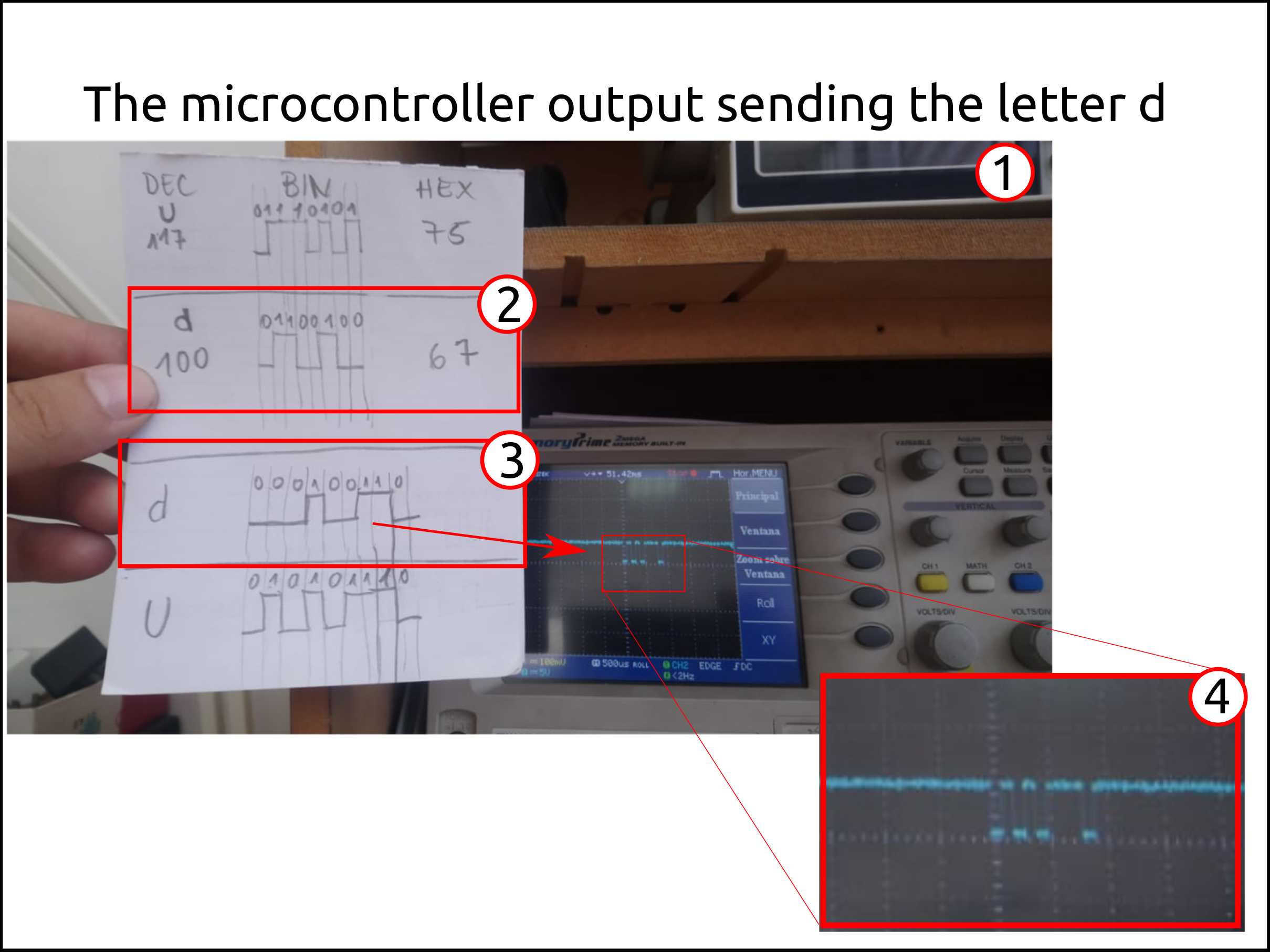
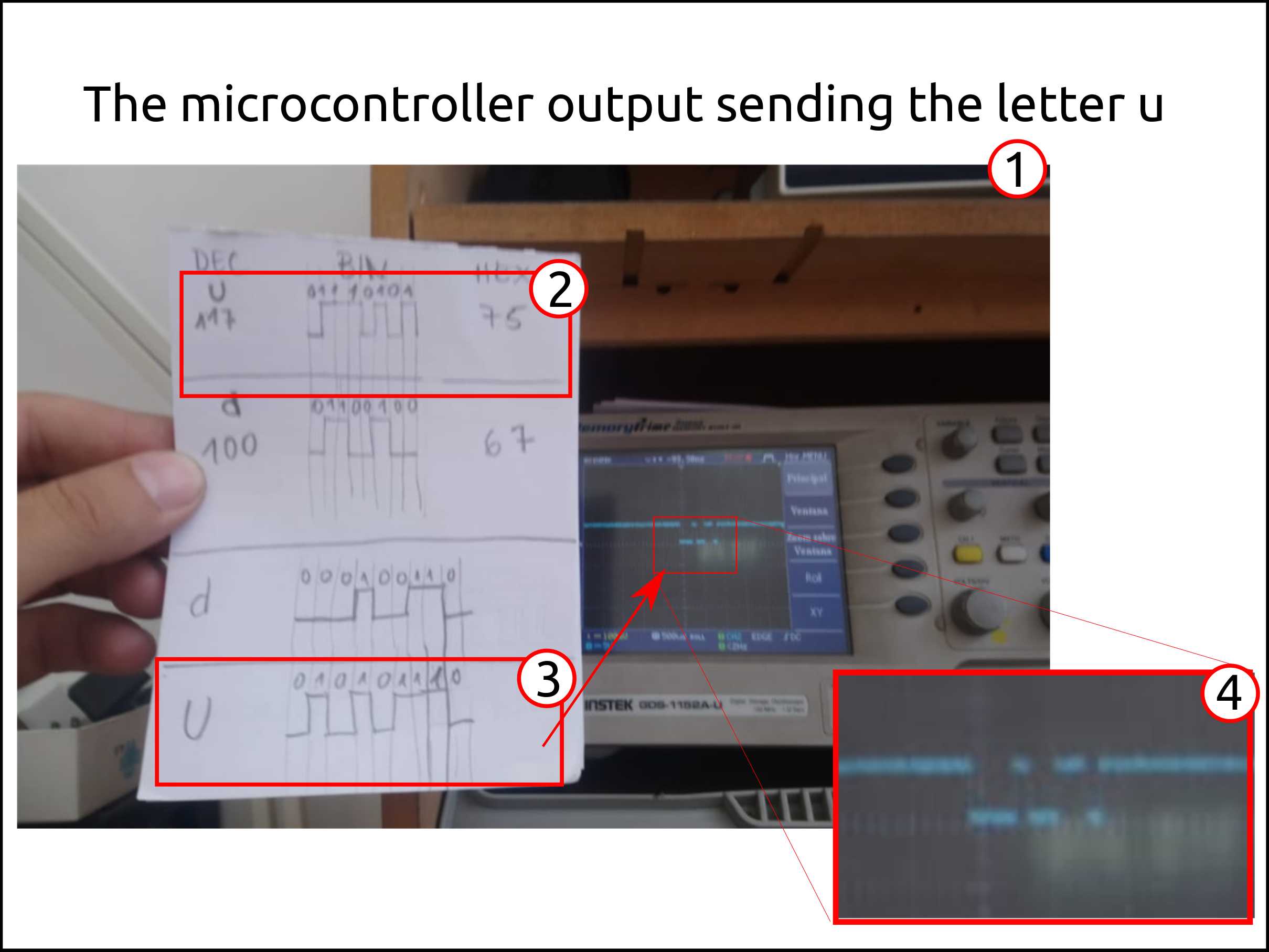
This is the comparison between the signal that is sent by the hello button board and the expected value.
-
The letter d in binany .
-
Signal expected.
-
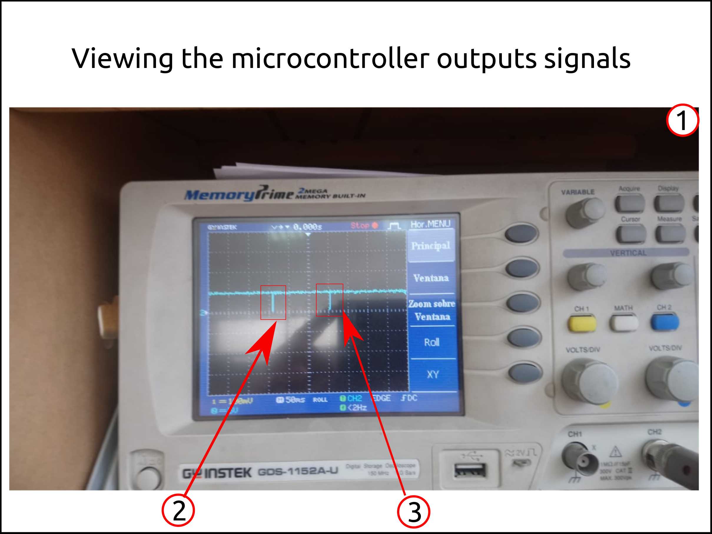
The signal measured.
-
This is the comparison between the signal that is sent by the hello button board and the expected value.
-
The letter u in binany .
-
Signal expected.
-
The signal measured.
-
Here we see the moment where the button was pressed and released showing and space between them that means the time I already pressed.
-
Letter d.
-
Letter u.
Faced problems and solutions working with the hello button
Problems
- The only problem was during the signal measuring the I could not figured out why the output signal was HIGH every time that the button is not pressed.
Solutions
- The solution was to draw what signal I have to expect and compare with it.
Files Hello Button

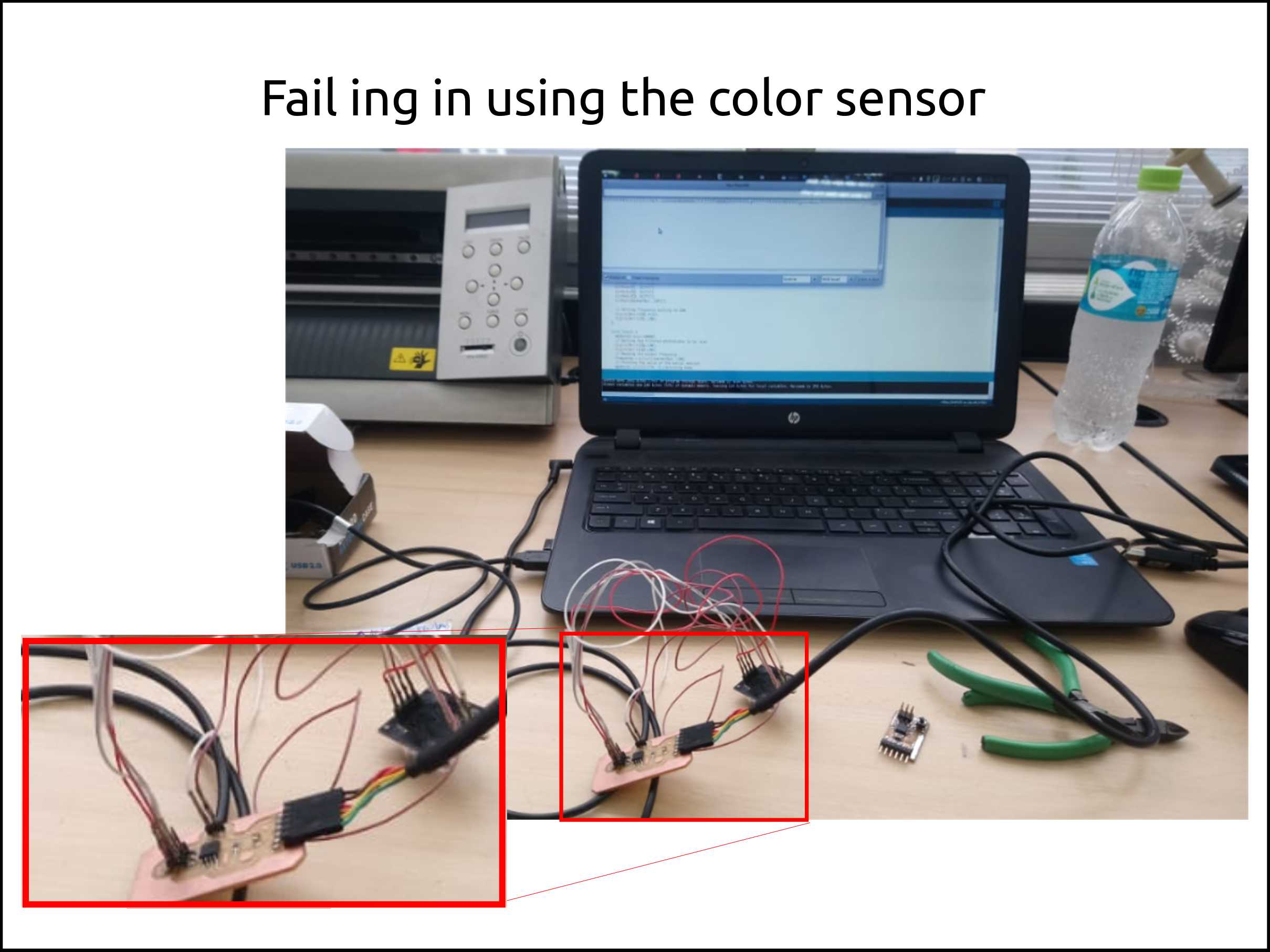
Failure (Color Sensor) :(
Color Sensor Code
This was the code I tried.
My Color sensor does not work prbably because sensor board issues or the sensor was too old.
My source is randommer tutorials. Here the author uses an arduino UNO, modified the code adding the serial software instead of the serial hardware.
If you have a new sensor color board you have to try this code. Good luck!
#include <SoftwareSerial.h>
SoftwareSerial mySerial(1, 2); // RX, TX

// TCS230 or TCS3200 pins wiring to Arduino
#define S0 4
#define S1 5
#define S2 6
#define S3 7
#define sensorOut 3

// Stores frequency read by the photodiodes
int redFrequency = 0;
int greenFrequency = 0;
int blueFrequency = 0;

void setup() {
  // Setting the outputs
  pinMode(S0, OUTPUT);
  pinMode(S1, OUTPUT);
  pinMode(S2, OUTPUT);
  pinMode(S3, OUTPUT);

  // Setting the sensorOut as an input
  pinMode(sensorOut, INPUT);

  // Setting frequency scaling to 20%
  digitalWrite(S0,HIGH);
  digitalWrite(S1,LOW);

   // Begins serial communication
  Serial.begin(9600);
}
void loop() {
  // Setting RED (R) filtered photodiodes to be read
  digitalWrite(S2,LOW);
  digitalWrite(S3,LOW);

  // Reading the output frequency
  redFrequency = pulseIn(sensorOut, LOW);

   // Printing the RED (R) value
  mySerial.print("R = ");
  mySerial.print(redFrequency);
  delay(100);

  // Setting GREEN (G) filtered photodiodes to be read
  digitalWrite(S2,HIGH);
  digitalWrite(S3,HIGH);

  // Reading the output frequency
  greenFrequency = pulseIn(sensorOut, LOW);

  // Printing the GREEN (G) value
  mySerial.print(" G = ");
  mySerial.print(greenFrequency);
  delay(100);

  // Setting BLUE (B) filtered photodiodes to be read
  digitalWrite(S2,LOW);
  digitalWrite(S3,HIGH);

  // Reading the output frequency
  blueFrequency = pulseIn(sensorOut, LOW);

  // Printing the BLUE (B) value
  mySerial.print(" B = ");
  mySerial.println(blueFrequency);
  delay(100);
}
This is a trial of sensing the color that I failed. Here I show that I could program it and read the signal.
Faced problems and solutions working with the Color Sensor
Problems
-
The example of how to use it was using arduino libraries, but it uses serial comnunication in hardware.
-
The next problem was to measure the frequency of the sensor output (TCS3200). Because I started to write the code in AVR C I needed to use counters but I could not get any results.
Solutions
-
I searched about a software serial and I found it, SoftwareSerial arduino library. This library allows you to communicate through serial without strictly having the UART module in the chip.
-
The solution was write in arduino C.
Digital dimmer
After failing using the color sensor I decided to do a digital dimmer. Where the main purpose is to read the voltage variation from a potentiometer and read followed by a ADC conversion with the attiny45 and the put the proportional value in a PWM signal to a LED.
#include <SoftwareSerial.h>
SoftwareSerial mySerial(11, 2); // RX, TX

int led = 0;       // pin to which LED is attached
int pot = A2;      // analog pin to which potentiometer is attached
int value;         // variable to read the value from the analog pin
int outputValue;   // output value to the analogwrite

void setup() {

  pinMode(led, OUTPUT); //sent the pin as an output


}

void loop() {

  mySerial.begin(9600);         //start the serial software comunication
  value = analogRead(pot);      // reads the value of potentiometer (ranging from 0 and 1023)
  mySerial.print("sensor = ");  //message
  mySerial.print(value);        //message
  outputValue = map(value, 0, 1023, 0, 255); // scale it to use it with analogWrite
  analogWrite(led, outputValue);             // set the analog out value
  // print the results to the Serial Monitor:
  mySerial.print("\t output = ");
  mySerial.println(outputValue);
  delay(2);                            // wait for 2 milliseconds for
                                       // analog-to-digital converter to settle
}
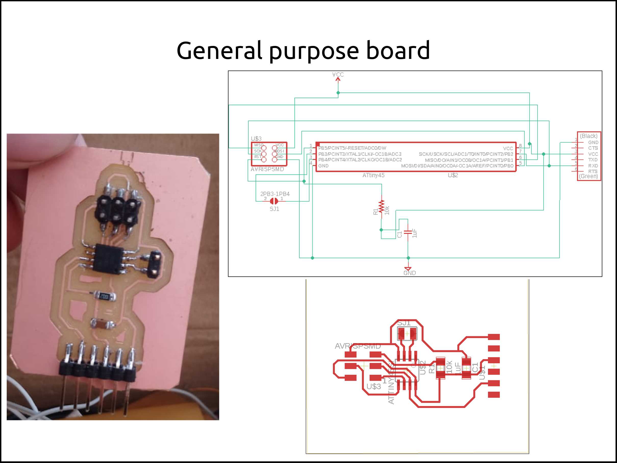
General purpose board
This board I used for the color sensor and the the digital dimmer.
General purpose board Components
| Component | SMD Code | Quantity |
|---|---|---|
| ATtiny45 or ATtiny85 | TINY45 or TINY85 | 1 |
| 10kΩ resistor | 1002 | 1 |
| 1x6 pin header male | NONE | 1 |
| 1x2 pin header male | NONE | 1 |
| 1uF capacitor | NONE | 1 |
| 2x3 pin header | NONE | 1 |
Here you can see my general purpose board. I have to mention that doing this board was the last time I used MODS.
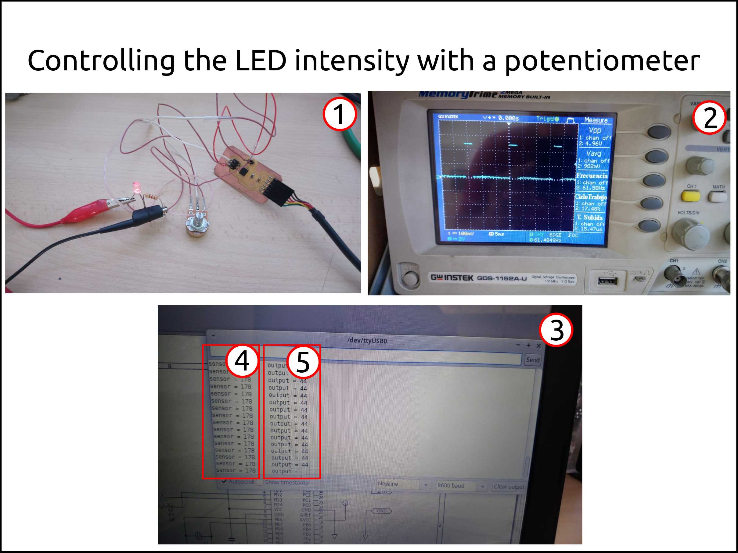
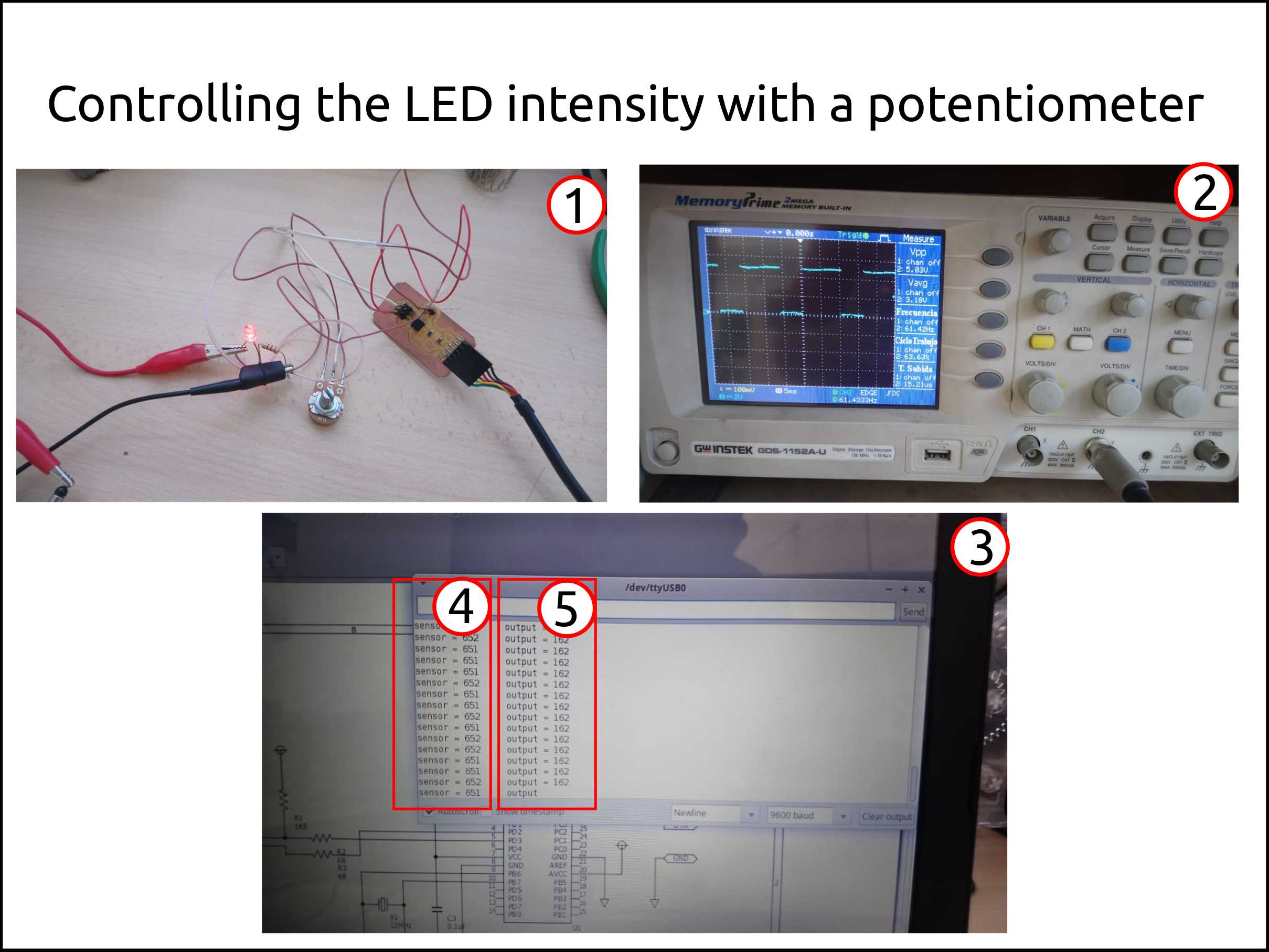
-
Here you can see the the digital dimmer working. This device uses a LED as a load and a Potentiometer as analogical input.
-
This is the image in the oscilloscope of the output of the PWM.
-
This is the serial monitor build-in the arduino IDE.
-
These are lectures of the analigic input that changes from 0 to 1024, depending of the microcontroller you are using.
-
These are the lecture of the PWM valuer the is applied to the load, in other words, applied to the LED.
Files digital dimmer

What I learned this week?
I learned about V-USB that is:
V-USB is a software-only implementation of a low-speed USB device for Atmel’s AVR® microcontrollers, making it possible to build USB hardware with almost any AVR® microcontroller, not requiring any additional chip.
I also learned the Variety of All Projects Based on V-USB
I found the information above questioning how to use an ATtiny45 as a USB-RS232 Converter.
I learned about SoftwareSerial communication.