Week 12
-
OUPUT DEVICES
Group Assignment
Measure the power consumption of an output device.
Individual Assignment
Add an output device to a microcontroller board you've designed, and program it to do something.
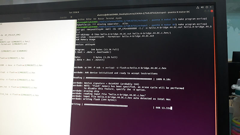
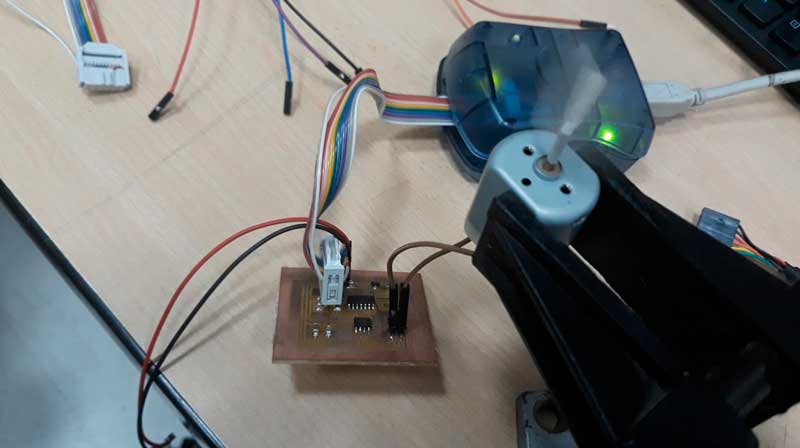
Programming a board to control a DC motor(INDIVIDUAL ASSIGNMENT)
I made a sample board (a Neil's board) to get familiar with the process of made a board (with output) and program it. Naturally, just for practice. This board controls a DC motor.
Programming a board to control a unipolar stepper motor(INDIVIDUAL ASSIGNMENT)
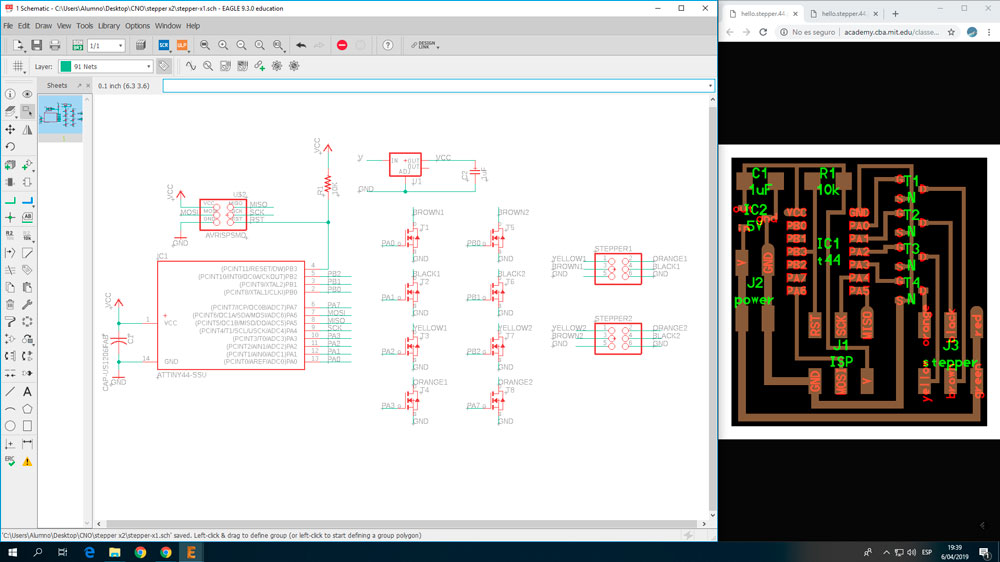
-Electronic design
For this week, I decided to make a PCB to control a couple of unipolar stepper motor. I think this will be useful for my final project, so I started with a sample of Neil (again), but I modified it, to control two steppers.
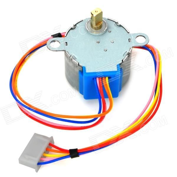
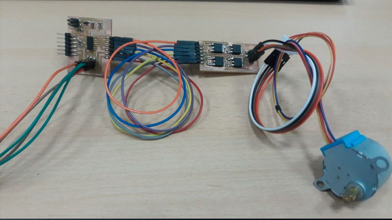
By the way, this is the stepper that I have: 28BYJ-48 .
I traced the schematics and add the needed components to the new stepper. Then, I placed the components on the board.
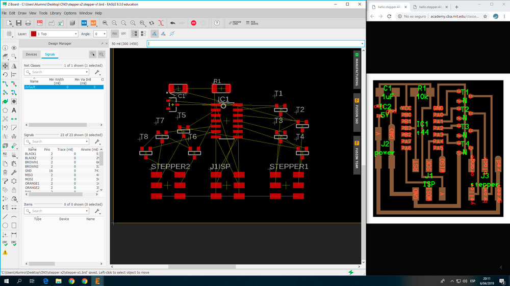
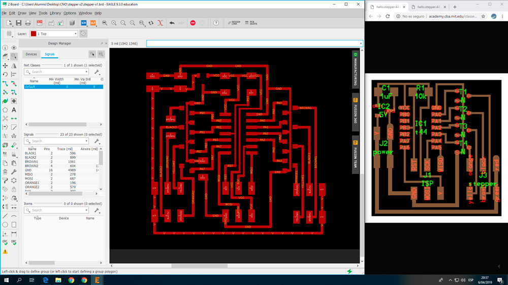
Later than a couple hours, I got my board design finished.
The components looked like this.
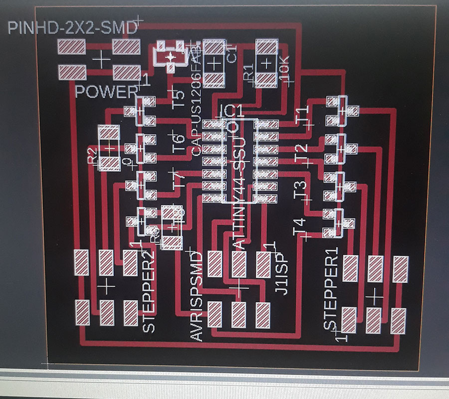
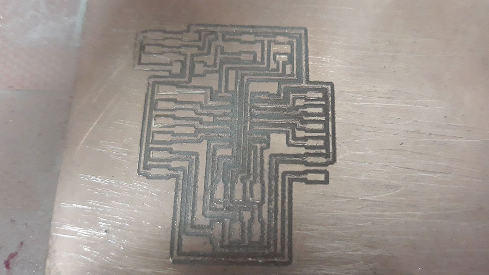
Milling the board
This design was milled on the Modela CNC machine, an the result was this.
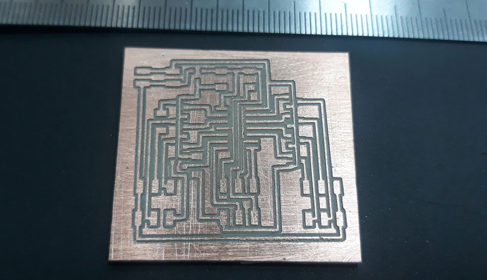
After that, I noticed there are no Mosfet N channel of 30V but 50V. These has different footprints. The mosfets on stock, are bigger than I considered. So my nice new PCB was unuseful. I has to back to the design again.
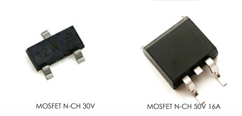
The stock mosfets are really bigger than the others, so I decided to divide the PCB. On piece will contain the micro controller and programming pins. The other piece will contain the mosfets and the control pins to the stepper.
Redesign of the board
The schematic was redesigned to includes the FTDI jumpers and the new mosfets.
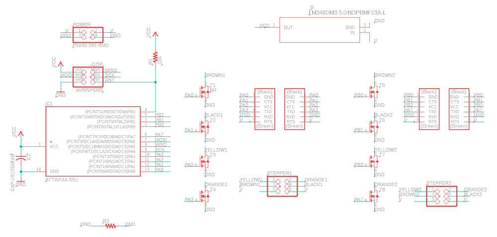
Then, the second part of the board, needs to be arranged too.
At this point, I decided make just one board with mosfets, due to the another one is the same.
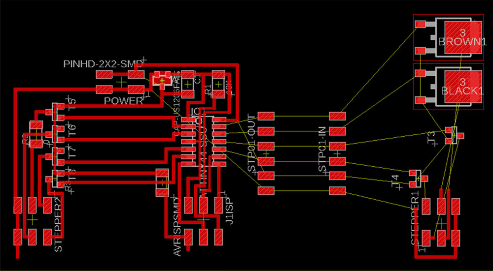
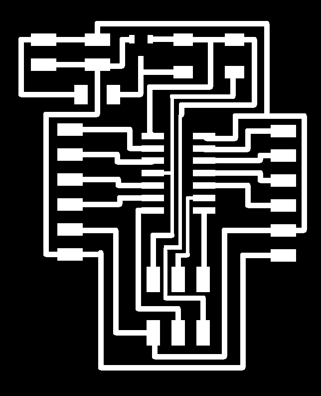
Finally, the new design lokks like this:

This is the MCU board image to mill.
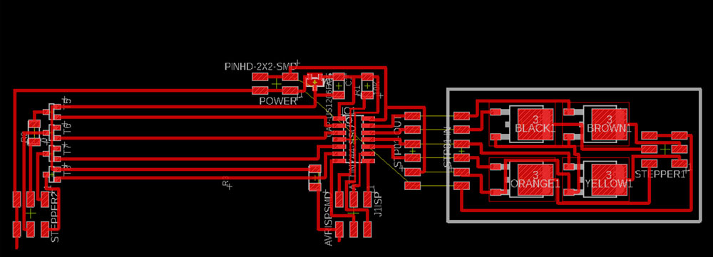
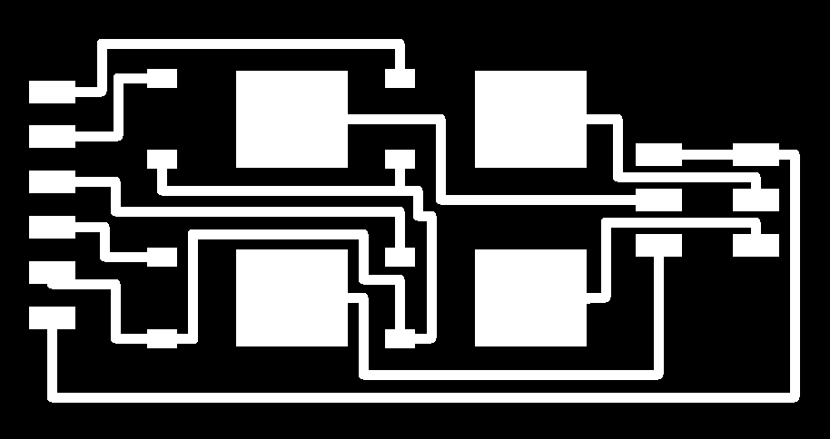
And this is the stepper board image to be milled.
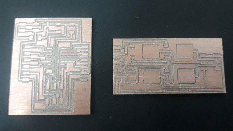
Milling the new boards design
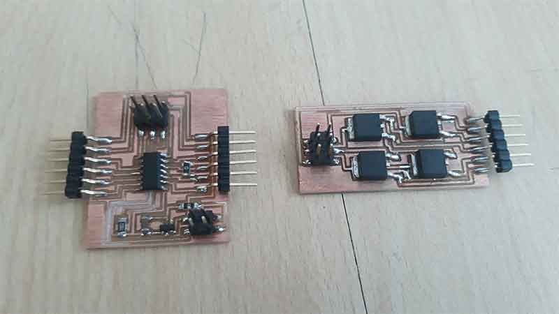
After that inconvenient, the new PCB was milled and the result is this:
After that, I solder the components to the boards. The next 2 videos, shows the process.
Finally, the new boards looks like this:
Programming
To do this program I modified the Neil's code to control two steppers instead one. The process of load the program is the same I used on assigment on week 9 (to read about, follow this link).
              #include < avr/io.h>
              #include < util/delay.h>

              #define output(directions,pin) (directions |= pin) // set port direction for output
              #define set(port,pin) (port |= pin) // set port pin
              #define clear(port,pin) (port &= (~pin)) // clear port pin
              #define pin_test(pins,pin) (pins & pin) // test for port pin
              #define bit_test(byte,bit) (byte & (1 << bit)) // test for bit set

              #define MOSFET_port PORTA // MOSFET port
              #define MOSFET_direction DDRA // MOSFET direction
              #define brown (1 << PA0) // MOSFET output pins
              #define black (1 << PA1) // "
              #define yellow (1 << PA2) // "
              #define orange (1 << PA3) // "
              #define on_delay() _delay_us(50) // PWM on time
              #define off_delay() _delay_us(10) // PWM off time
              #define PWM_count 200 // number of PWM cycles

              static uint8_t count;

              //
              // yellow, brown PWM pulse
              //
              void pulse_yellow_brown() {
                 for (count = 0; count < PWM_count; ++count) {
                    set(MOSFET_port, yellow);
                    set(MOSFET_port, brown);
                    on_delay();
                    clear(MOSFET_port, yellow);
                    clear(MOSFET_port, brown);
                    off_delay();
                    }
                 }
              //
              // yellow, black PWM pulse
              //
              void pulse_yellow_black() {
                 for (count = 0; count < PWM_count; ++count) {
                    set(MOSFET_port, yellow);
                    set(MOSFET_port, black);
                    on_delay();
                    clear(MOSFET_port, yellow);
                    clear(MOSFET_port, black);
                    off_delay();
                    }
                 }
              //
              // orange, brown PWM pulse
              //
              void pulse_orange_brown() {
                 for (count = 0; count < PWM_count; ++count) {
                    set(MOSFET_port, orange);
                    set(MOSFET_port, brown);
                    on_delay();
                    clear(MOSFET_port, orange);
                    clear(MOSFET_port, brown);
                    off_delay();
                    }
                 }
              //
              // orange, black PWM pulse
              //
              void pulse_orange_black() {
                 for (count = 0; count < PWM_count; ++count) {
                    set(MOSFET_port, orange);
                    set(MOSFET_port, black);
                    on_delay();
                    clear(MOSFET_port, orange);
                    clear(MOSFET_port, black);
                    off_delay();
                    }
                 }
              //
              // clockwise step
              //
              void step_cw() {
                 pulse_yellow_brown();
                 pulse_yellow_black();
                 pulse_orange_black();
                 pulse_orange_brown();
                 }
              //
              // counter-clockwise step
              //
              void step_ccw() {
                 pulse_orange_brown();
                 pulse_orange_black();
                 pulse_yellow_black();
                 pulse_yellow_brown();
                 }

              int main(void) {
                 //
                 // main
                 //
                 static uint8_t i,j;
                 //
                 // set clock divider to /1
                 //
                 CLKPR = (1 << CLKPCE);
                 CLKPR = (0 << CLKPS3) | (0 << CLKPS2) | (0 << CLKPS1) | (0 << CLKPS0);
                 //
                 // initialize MOSFET pins
                 //
                 clear(MOSFET_port, brown);
                 output(MOSFET_direction, brown);
                 clear(MOSFET_port, black);
                 output(MOSFET_direction, black);
                 clear(MOSFET_port, yellow);
                 output(MOSFET_direction, yellow);
                 clear(MOSFET_port, orange);
                 output(MOSFET_direction, orange);
                 //
                 // main loop
                 //
                 while (1) {
                    for (i = 0; i < 10; ++i) {
                       for (j = 0; j < i; ++j)
                          step_cw();
                       for (j = 0; j < i; ++j)
                          step_ccw();
                       }
                    for (i = 10; i > 0; --i) {
                       for (j = 0; j < i; ++j)
                          step_cw();
                       for (j = 0; j < i; ++j)
                          step_ccw();
                       }
                    }
                 }
The final result, looks like this:
Files of this assignment:
- stepper-x2-v2.brd (Design board)
- stepper-x2-v2.sch (Design schematic)
- stepper x2-V2-MICRO-EDGES.png (Milling file)
- stepper x2-V2-MICRO-TRACES.png (Milling file)
- stepper x2-V2-STEPPERBOARD-EDGE.png (Milling file)
- stepper x2-V2-STEPPERBOARD-TRACES.png (Milling file)
- stepper-x2-v2.c (Program)
<<< Go to Week 11 assignment | >>> Go to Week 13 assignments