Week 20
-
PROJECT DEVELOPMENT
Individual Assignment
Complete your final project, tracking your progress.
Project progress (INDIVIDUAL ASSIGNMENT)
This project is about a medical device. It will help patients with scoliosys, to correct their posture mechanically. My first ideas for actuator were rotary or linear servos, but following the Neil's feedback I read more about soft robotics. I found very nice projects that uses this kind of actuator.
(Taked from Youtube)
One of these project includes McKibben actuators, made of an cilindrical expandable globe, into a mesh. This actuator can contracts when the pressure air inside increase. The problem is the relative high pressure needed to act it.
First ideas
Corset with rotary servos.
Second idea
Softactuator, powered by pressure air..
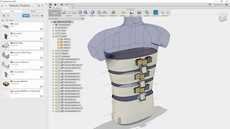
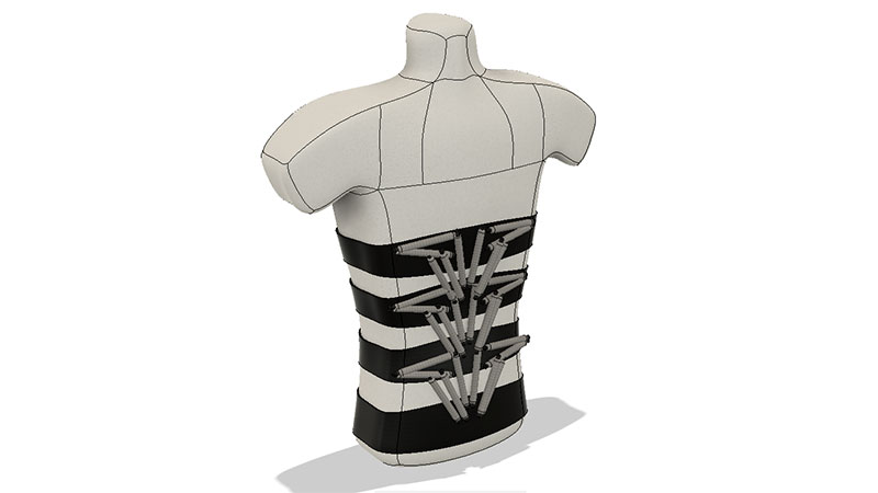
Mockup of the project
The softactuator placed over a belt.
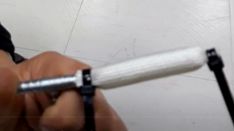
First actuator powered by pressure air
This actuator works, but needs a high pressure to operate.
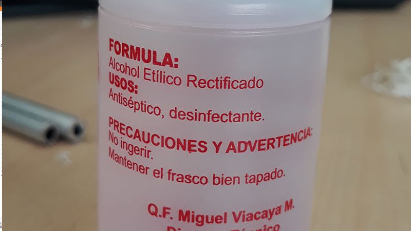
The next prototypes that I made were soft actuators too. These were made from silicone mainly, but this time, I tried another approach (taken form this link). Inside the silicone globe, I puted an electric resistance wire, and fill all the inside of the actuator with alcohol, then sealed.
(Taked from Youtube)
So, I tarted to made prototypes
The concept
The first idea was emulate the natural way the muscles create movements on the human body.
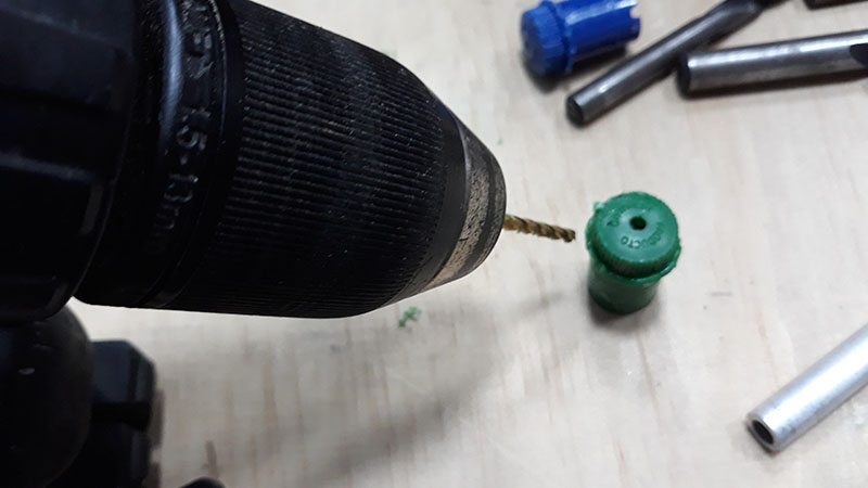
First actuator mold
I used a marker to made a fast mold.
First actuator mold
I used a marker to made a fast mold.
First actuator mold
The hole allows introduce a core to the mold.
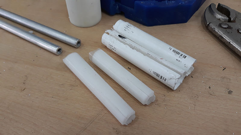
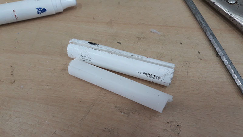
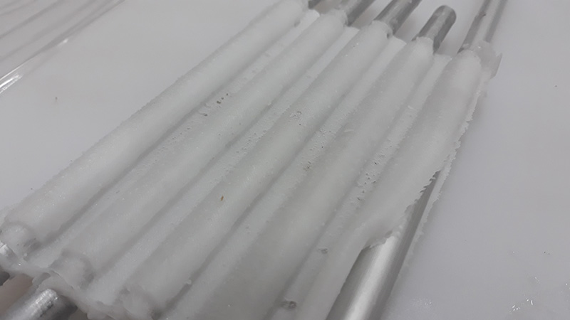
Core of mold
The core of the mold is a aluminum tube.
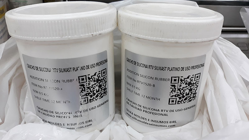
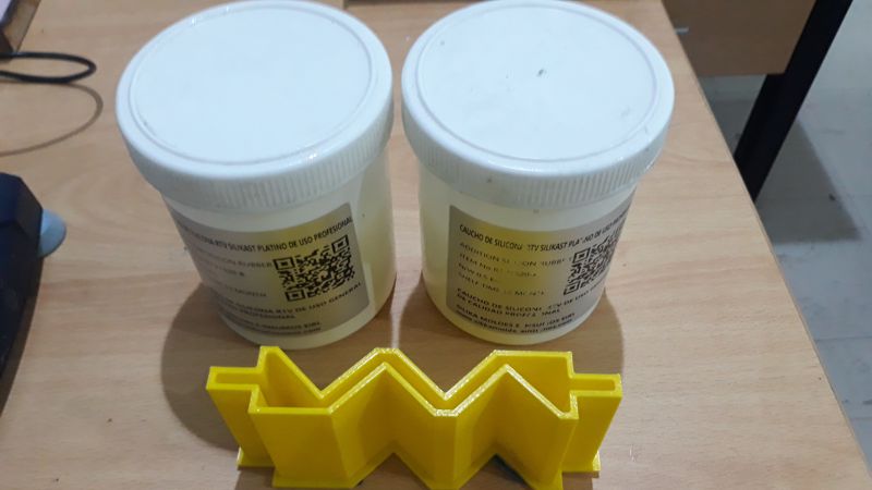
Cast silicone RTV 20
The material used to cast was platinum silicone bi-component. Hardness Shore A 20.
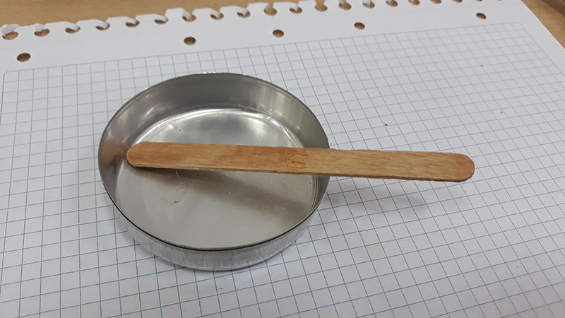
Some tools to cast
Some accesories were needed to make the casting..
The process of fabrication can be seen at the images.
When I tried to use this actuator, with alcohol inside, I couldnt make it work. The heat generated in the wire, was not enough to evaporate the liquid (and increase the volume) to generate the pressure inside, needed to expand the wall of silicone. So, I decide to tried with a thin wall and made a mold to achieve that.
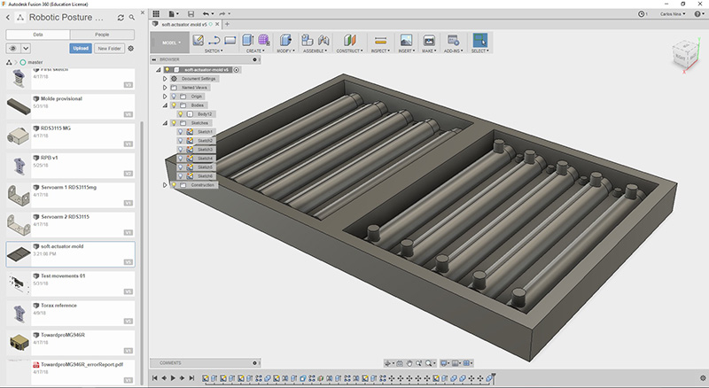
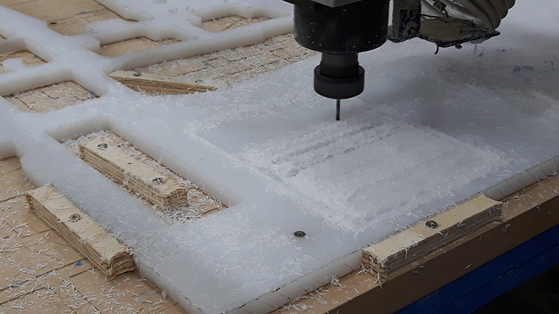
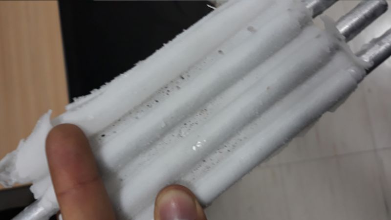
I decide to design and 3d print a mold, but the only material available on tha Fablab at that time was ABS on a machine most used with PLA. The result was the expected. It failed. After that, I decided modify the design, to use the CNC machine, to get the mold with polyurethane resin. Unfourtunelly, there was no wax aviable and I used nylon, but the surface finish of that material was very poor (at least with my mill tool). I decided to continue with the casting of the poliurethane and get the mold.
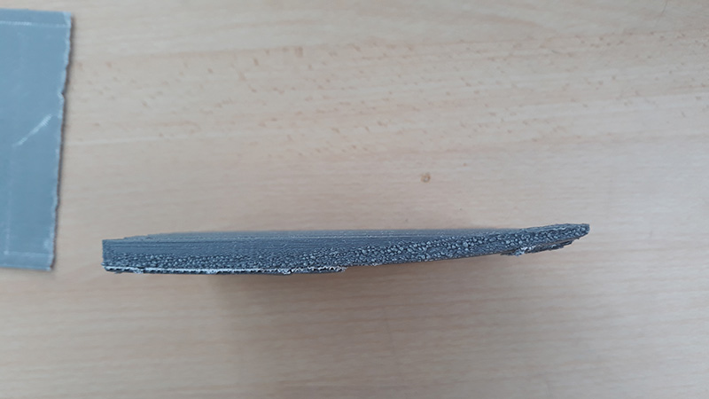
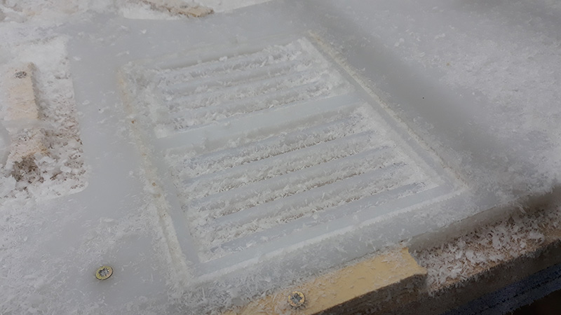
Saddly, due to the surface porous on the mold and the thin wall of silicone, the pieces resulted porous.
After that, I decide try a simpler approach than before. I found a simple way to act an soft actuator with negative pressure. So, I decide to try with this.
(Taked from Youtube)
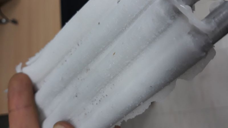
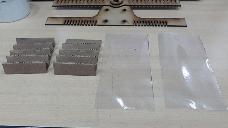
Looks simplier than before designs and require relative low pressures differences.So I started with a simple version, made of cardboard.
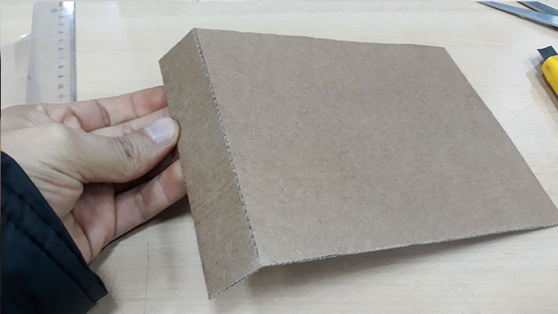
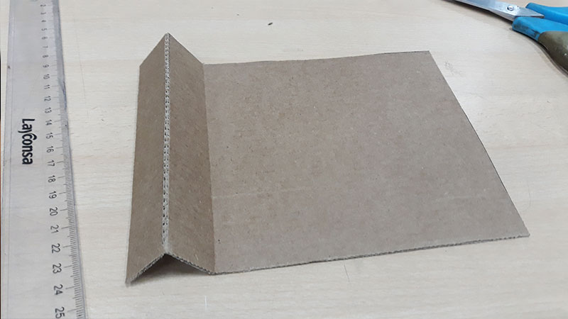
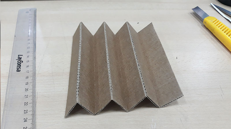
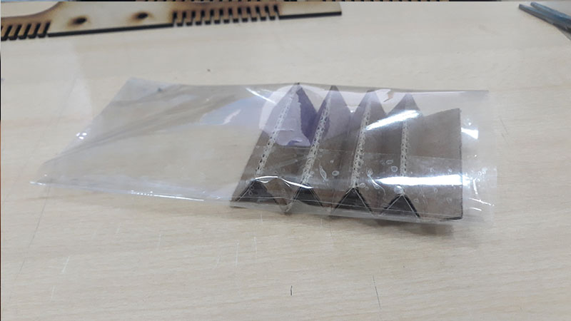
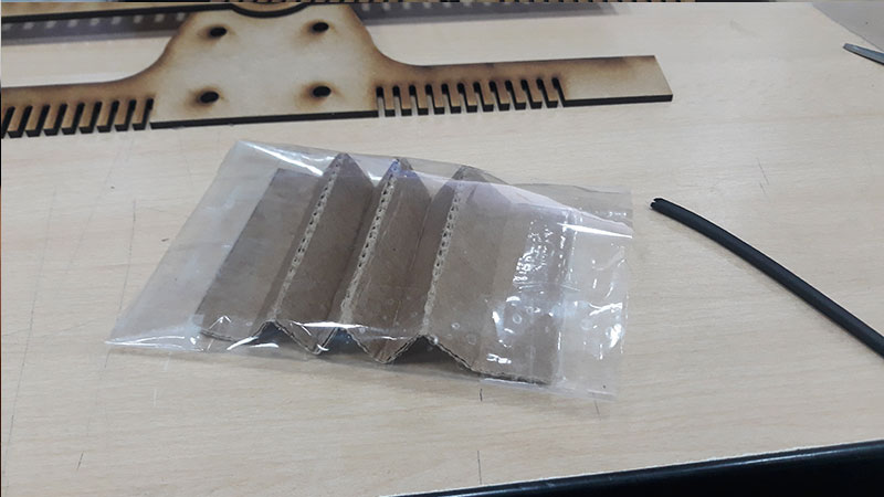
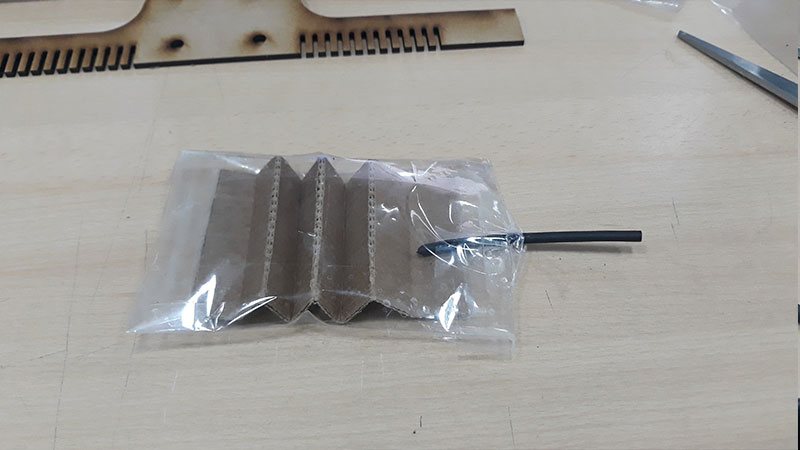
The test of this actuator was very successful.
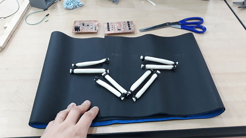
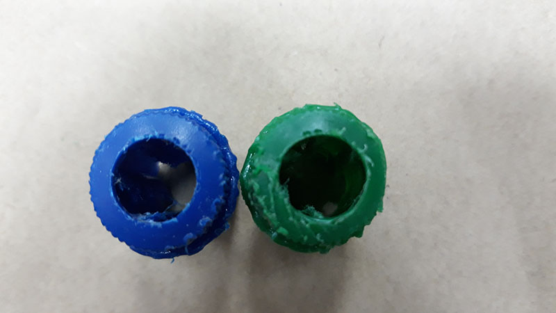
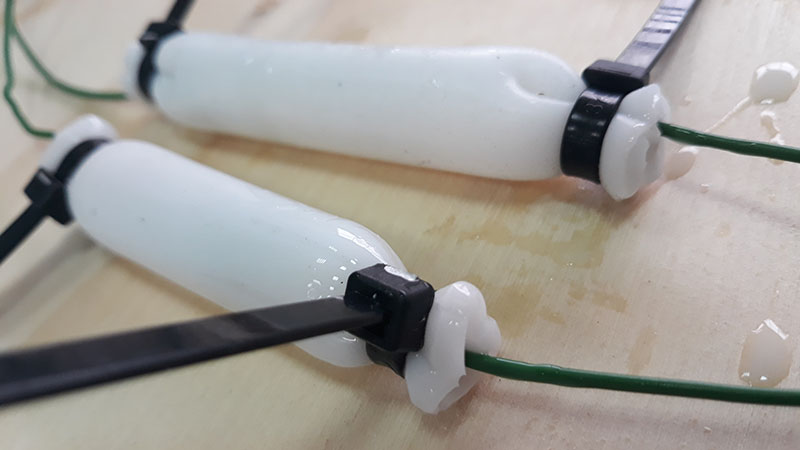
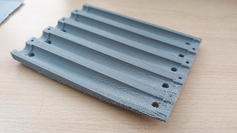
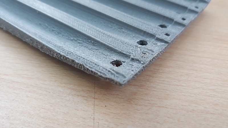
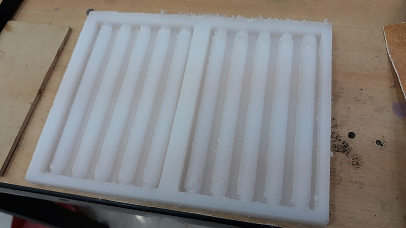
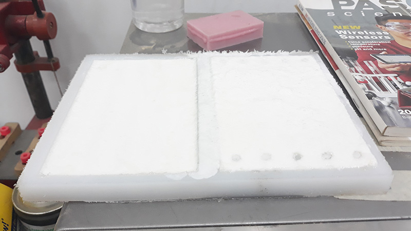
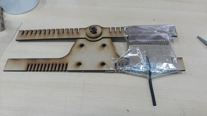
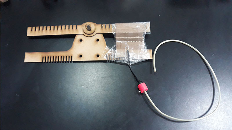
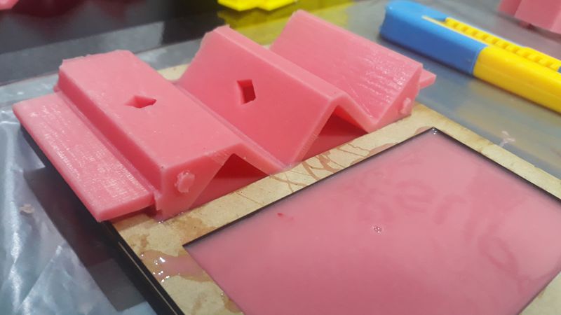
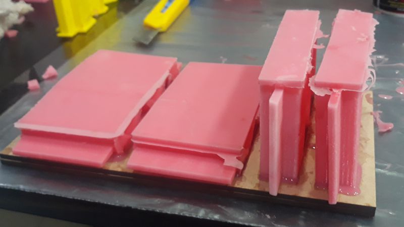
The next step was built a 3d printed mold and cast silicone to make a soft actuator. Actually I cast a couple of silicone variants, the first one a bicomponent platinum silicone RTV 20 (white color) and a silicone with catalyzer (pink color).
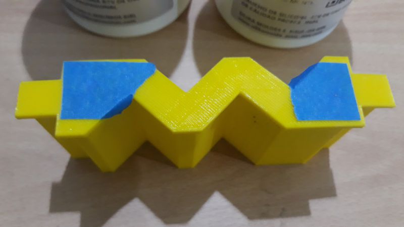
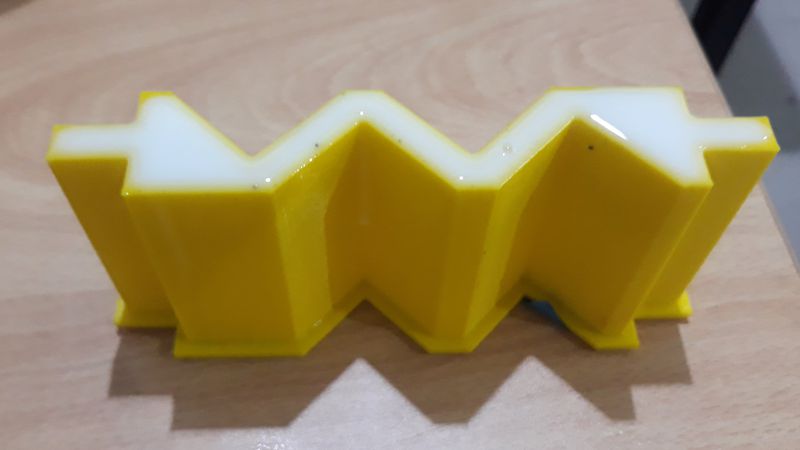
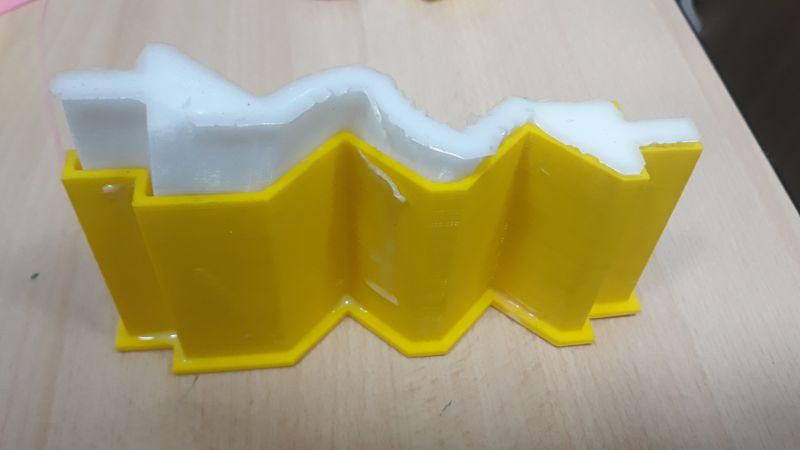
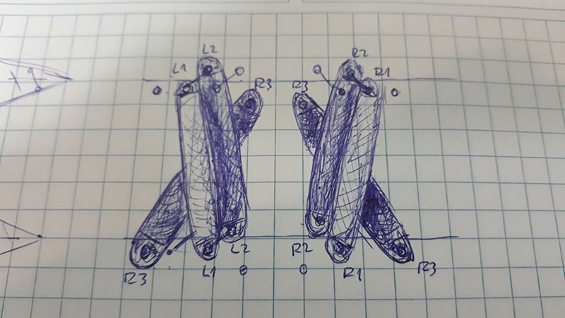
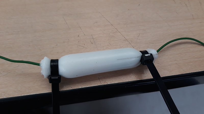
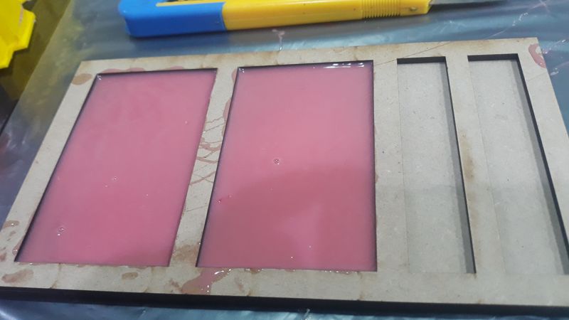
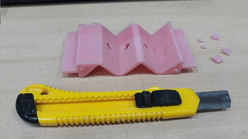
After that I taked a decision (not good at all). I complete the actuator with silicone walls. To do that, I made a frame of MDF. This allows cast a layer of silicone, then I placed the actuators over there and wait to cure. The result after some hours, was 4 complete soft actuators. Was very important, made some holes on the inner walls to the actuator BEFORE the casting of the external walls.
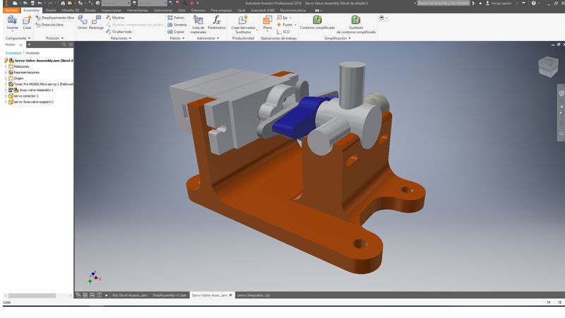
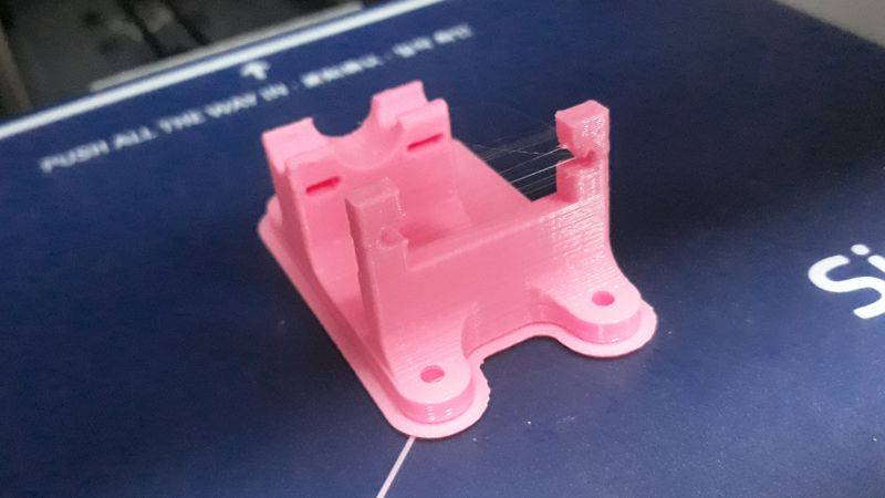
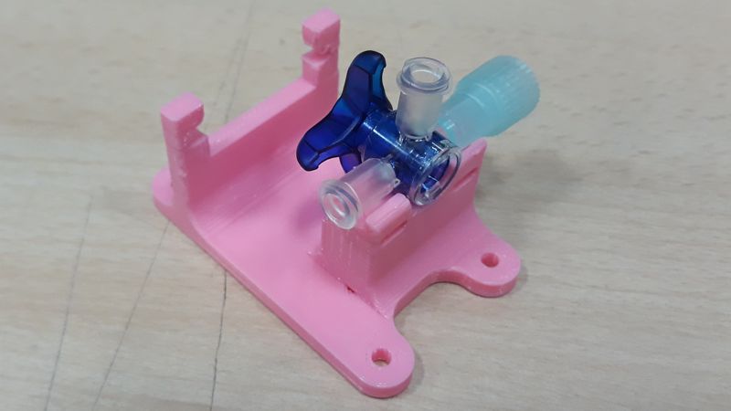
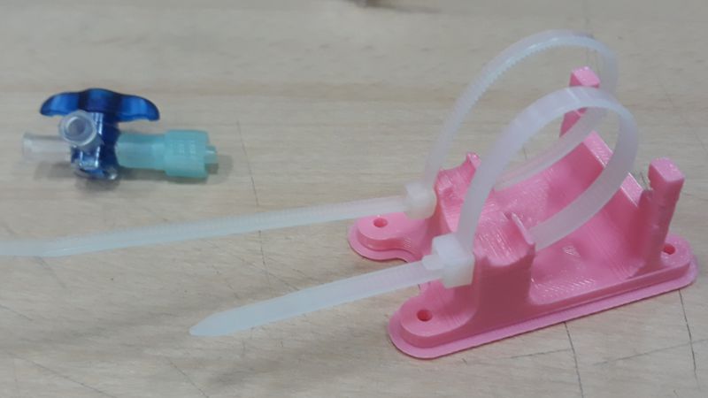
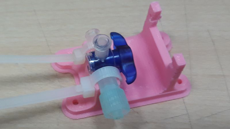
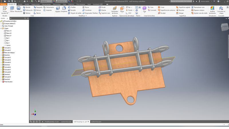
Once the actuator was ready, I designed a support to align the servo motor and a three way valve (used with venoclysis equipments). I 3d print it and fixed together with zip ties.
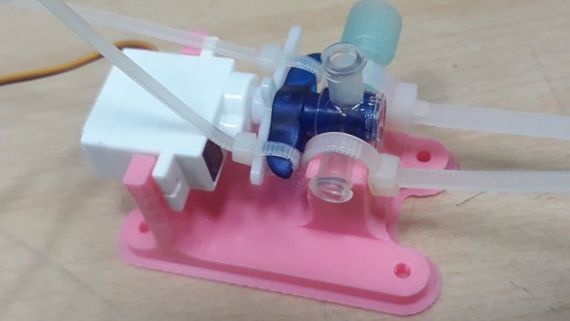
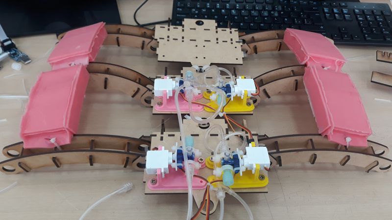
Finally, to integrate all the components, I designed a "boxes" to hold the supports, valves, servo motors and the Fabduino.
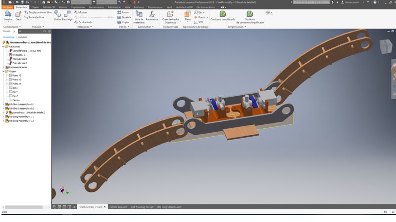
The result of assemble the supports, valves and hoose is this. To be honest, I was planning a lean prototype, but the size was defined by the servos and valves. I'm pretty sure I can make it smaller than this in a next iteration (And pretiest than this :).
Meanwhile, all this works was running, I was developing the software to control de servos (and valves) through a smartphone via bluetooth, communicating an Fabduino. This Fabduino, is connected to the servos, then open and close the valves, according the smartphone orders.
This code, stablish a serial communication between a bluetooth module HC-05 and the Fabduino. I was develop this in detail in week 14 assignment. The code, receive a number from the Android App, this number is used to identify what servomotor must open (turn to 0 degress) or close (turn to 100 degress) a valve.
            #include < SoftwareSerial.h>
            #include < Servo.h>

            //Bluetooth definitions
            #define RxD 10
            #define TxD 11
            #define DEBUG_ENABLED  1
            SoftwareSerial blueToothSerial(RxD,TxD);
            int led_test = 8;

            //Servo definitions
            Servo L1;
            int pinL1 = 2; // byte
            Servo R1;
            int pinR1 = 3;
            Servo L2;
            int pinL2 = 4;
            Servo R2;
            int pinR2 = 5;

            void setupBlueToothConnection(){

              blueToothSerial.begin(9600); //Set BluetoothBee BaudRate to default baud rate 38400
              blueToothSerial.print("\r\n+STWMOD=0\r\n"); //set the bluetooth work in slave mode
              blueToothSerial.print("\r\n+STNA=HC-05\r\n"); //set the bluetooth name as "HC-05"
              blueToothSerial.print("\r\n+STOAUT=1\r\n"); // Permit Paired device to connect me
              blueToothSerial.print("\r\n+STAUTO=0\r\n"); // Auto-connection should be forbidden here
              delay(2000); // This delay is required.
              //blueToothSerial.print("\r\n+INQ=1\r\n"); //make the slave bluetooth inquirable
              blueToothSerial.print("bluetooth connected!\n");
              delay(2000); // This delay is required.
              blueToothSerial.flush();

            }


            void setup(){
              //Bluetooth setup-----------
              pinMode(RxD, INPUT);
              pinMode(TxD, OUTPUT);
              setupBlueToothConnection();
              pinMode(led_test,OUTPUT);
              digitalWrite(led_test,LOW); //led for testing

              //Servo setup--------------
              Serial.begin(9600);

              L1.attach(pinL1);
              L1.write(90); //Degrees = CLOSE
              R1.attach(pinR1);
              R1.write(90); //Degrees = CLOSE
              L2.attach(pinL2);
              L2.write(90); //Degrees = CLOSE
              R2.attach(pinR2);
              R2.write(90); //Degrees = CLOSE

            }

            void loop(){

              char recived_char;
              char last_recived_char;

              while(1){

                //check if there's any data sent from the remote bluetooth shield
                if(blueToothSerial.available()){

                  recived_char = blueToothSerial.read();

                //Servo L1--------------
                  if( recived_char == '1' ){

                    digitalWrite(led_test,HIGH);
                    L1.write(0);//turn 0 degrees = OPEN
                    last_recived_char = recived_char;
                    delay(20);
                  }
                  else if( recived_char == '0' ){

                      digitalWrite(led_test,LOW);
                      L1.write(100);//return to 100 degrees = CLOSE
                      last_recived_char = recived_char;
                      delay(20);
                  }


                  //Servo R1--------------
                  if( recived_char == '2' ){

                    digitalWrite(led_test,HIGH);
                    R1.write(0);//turn 0 degrees = OPEN
                    last_recived_char = recived_char;
                    delay(20);
                  }
                  else if( recived_char == '3' ){

                      digitalWrite(led_test,LOW);
                      R1.write(100);//return to 100 degrees = CLOSE
                      last_recived_char = recived_char;
                      delay(20);
                  }


                  //Servo L2--------------
                  if( recived_char == '4' ){

                    digitalWrite(led_test,HIGH);
                    L2.write(0);//turn 0 degrees = OPEN
                    last_recived_char = recived_char;
                    delay(20);
                  }
                  else if( recived_char == '5' ){

                      digitalWrite(led_test,LOW);
                      L2.write(100);//return to 100 degrees = CLOSE
                      last_recived_char = recived_char;
                      delay(20);
                  }

                  //Servo R2--------------
                  if( recived_char == '6' ){

                    digitalWrite(led_test,HIGH);
                    R2.write(0);//turn 0 degrees = OPEN
                    last_recived_char = recived_char;
                    delay(20);
                  }
                  else if( recived_char == '7' ){

                      digitalWrite(led_test,LOW);
                      R2.write(100);//return to 100 degrees = CLOSE
                      last_recived_char = recived_char;
                      delay(20);
                  }


                }

              }

            }
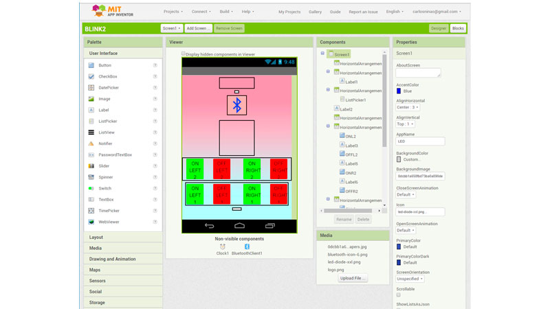
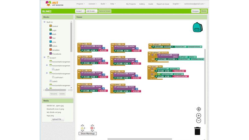
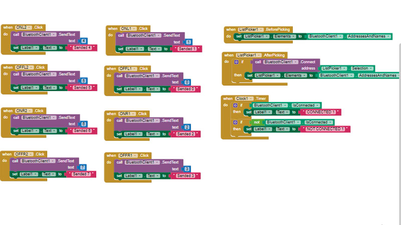
The mobile app that send the instruction from the user, was made with MIT App Inventor.
The process of develop an mobile app for Android, was developed on the week 16 assignment.
The app I made looks like this:
(the apk and the project to built it, can be downloaded from the link at the end of page).
Finally, after all the work (So many hours). The final test worked!
Final comments
what tasks have been completed, and what tasks remain?
I completed: the software loaded to the Fabduino, mobile Android application, 3d printed supports to servos and valves, assembly of the machine working togheter.
The tasks remain are: Improve the brace with another material (no MDF), manage the cables and hoses, Use some batteries and a portable vacuum pump.
what has worked? what hasn’t?
Worked: The software on Fabduino receive the values from the HC-05 bluetooth module, via serial communication, the mobile app send the correct values to the Fabduino.
The micro servos can move the valves (slowly, but did it).
Not worked: The actuator is too rigid. ON the test, I used a thin film of plastic to enclosure, but when used silicone the actuator turns rigid and the contraction reduces. This is tha way that would be work with a thin enclosure:
what questions need to be resolved?
I think the main question is: Can I get the pressure needed from a portable vacuum pump?
This is a feature that makes the device portable. I demostrated that it work, but I would like to do this entirely portable.
what will happen when?
I will try a portable vacuum pump with LIPO batteries and improve the brace design with other materials.
Basically, I will continue with the development until make it practical enough.
Once I reach that, I will need to test it with the supervision of medics, to guarantee a proper function.
What have you learned?
- I think the idea of made the entire actuator with silicone, wasn't good. The outer material must be thin and inextensible, to get a larger contraction of the actuator.
- The torque of the micro servos are barely the needed to turn the valves. I think must analyze another option to turn the valves (or use larger servos).
- Cable and hoose management must be considered carefully on a next iteration and integrated with the design.
- This prototype use an external vacuum pump. I think t must be replaced by an portable option. I will check the air pumps of the portable blood pressure monitors.
Files of this assignment:
- Robotic-Brace-v2.c (Fabduino code)
- Robotic-Brace-v2.aia (App Inventor Project)
- Robotic-Brace-v2.apk (Android App)