 FabAcademy 2019
ELECTRONICS DESIGN
The practice of this week is to modify the design of the plate "Echo Hello- World" in a suitable software and finally make it. Later in a subsequent task will be scheduled for a particular application. .
1. Group Assignment
Use the test equipment in your lab to observe the operation of a microcontroller circuit board.
1.1 Using the equipment
Carlos Nina. - Ivan Callupe.
Diego Santa Cruz.
Team Group
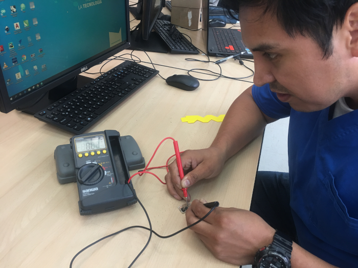
1.1.1 Multimeter
A multimeter, also known as a volt-ohm meter, is a handheld tester used to measure electrical voltage, current (amperage), resistance, and other values. Multimeters come in analog and digital versions and are useful for everything from simple tests, like measuring battery voltage, to detecting faults and complex diagnostics. They are one of the tools preferred by electricians for troubleshooting electrical problems on motors, appliances, circuits, power supplies, and wiring systems. DIYers also can learn to use multimeters for basic measurements around the house.(
_
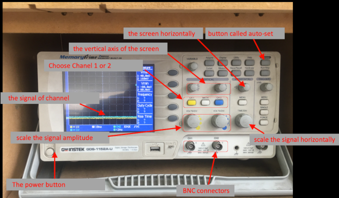
1.1.2 Oscilloscope
Oscilloscopes, or scopes are an important tool in the armoury of the electronics engineer or tester. An oscilloscope enables waveforms to be seen and in this way makes it very much easier to see any problems occurring in an electronics circuit.
In view of the advantages which they posses, oscilloscopes are an essential tool for any electronics laboratory or area testing electronics hardware.
The name oscilloscope, comes from the fact that it enables oscillations to be viewed. Sometimes the name cathode-ray oscilloscope, or CRO is used. The reason for this is that cathode ray tubes (CRT) used to be used to enable the waveforms to be displayed.(
_
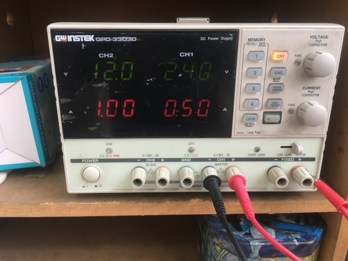
1.1.2 Power supply
Power supplies are amongst the most popular pieces of electronic test equipment. This isn't surprising, as controlled electrical energy is used in a tremendous number of ways. In this guide, we'll look at a variety of different types of power supplies, their controls, how they operate, and some examples of their application.
(
_
2. Individual Assignment
redraw the echo hello-world board, add (at least) a button and LED (with current-limiting resistor) check the design rules, make it, and test it extra credit: simulate its operation
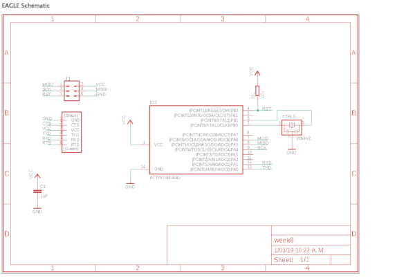
2.1 ECHO HELLO_WORDL BOARD
the ECHO HELLO_WORDL BOARD is a schematic file which contains electronic components (ATtiny44, capacitor, resonator, etc). We will have to redraw the circuit and also add a button and an LED.Using any software (EAGLE or KICAD). I chose EAGLE, because I was more familiar with the management of this software.
2.2 Using EAGLE
the ECHO HELLO_WORDL BOARD is a schematic file which contains electronic components (ATtiny44, capacitor, resonator, etc). We will have to redraw the circuit and also add a button and an LED.Using any software (EAGLE or KICAD). I chose EAGLE, because I was more familiar with the management of this software.
2.3 Using EAGLE
After downloading "eagle", we must add the libraries provided by the FabAcademy. This document can be found by entering fab academy tutorials.
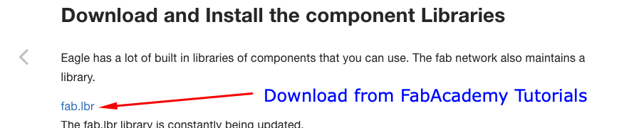
_
The document "fab.lbr", we copy it the following address: documents / EAGLE / libreries (for IsoX).
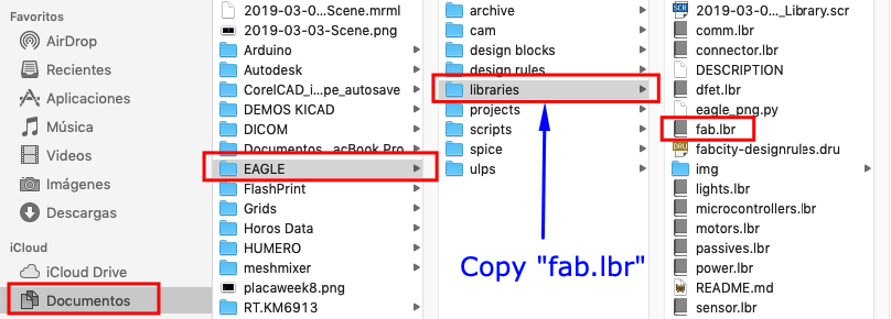
_
When opening EAGLE, we go to libraries, where we can find the file "fab.lbr". We put it to use and we open it. Here we can find all the necessary components to redraw our electronic circuit.
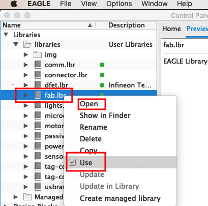
_
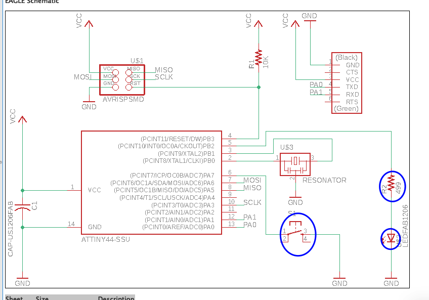
In our schematic design, we can add the LED and the pushbutton.
After creating the schematic design of the circuit. The design of the electronic card tracks is done. This can take time. Because you have to have the width of each track and avoid intersecting.
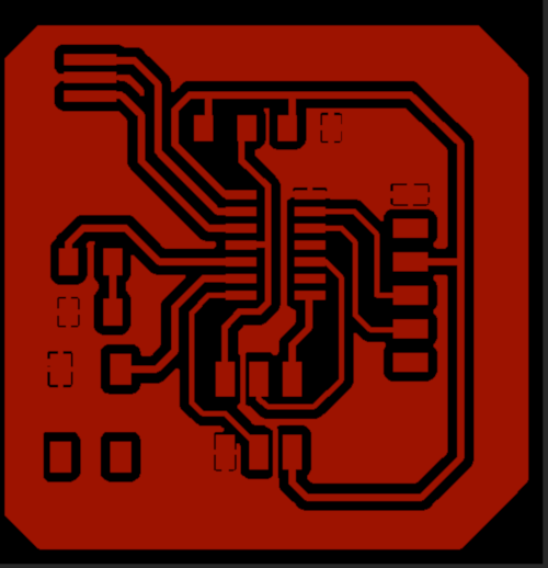
_
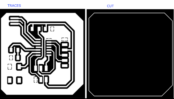
After finishing the design. The strokes and the edge of the card are exported. these must be in .PNG format and in monochromatic style.
2.4 MILLING, CUTTING AND SOLDERING
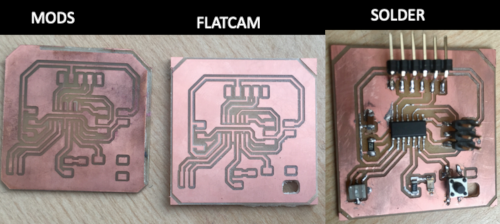
Using the MODS, the cutting path was generated. Of the files created in EAGLE in PNG format.
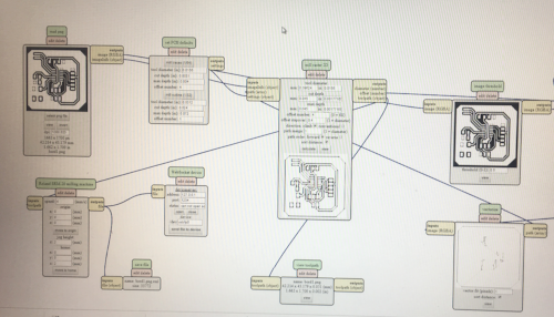
_
Using the MODS, the cutting path was generated. Of the files created in EAGLE in PNG format.
_
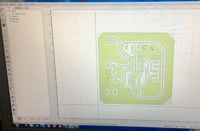
When comparing the two designs, I drew the path made by FLATCAM. Because the tracks generated were better finished. and I made the soldier of each component.
_
2.5 TESTING
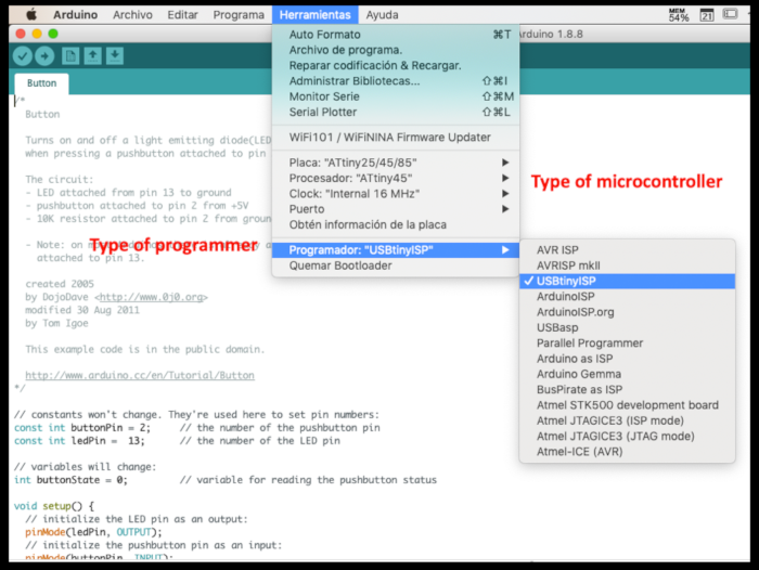
Through the arduino software try to connect to the circuit. But not achieving a communication.Yo utilicé el attiny 45 como programador ISP. El cual es necesario para programar el microcontrolador.
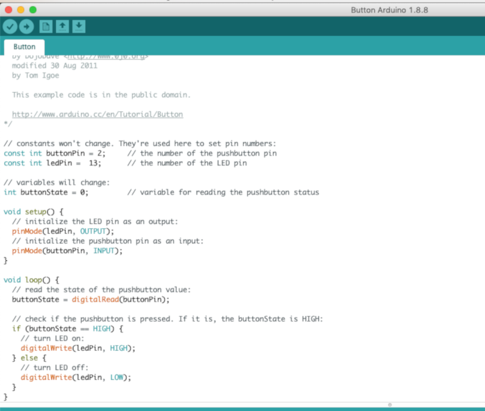
The program downloaded to the microcontroller is a function where the button turns the LED on and off.
Contact Me
Feel free to contact me via email or phone.