Fourth assignment
Part III
Date
6 February 2019
design and laser cut
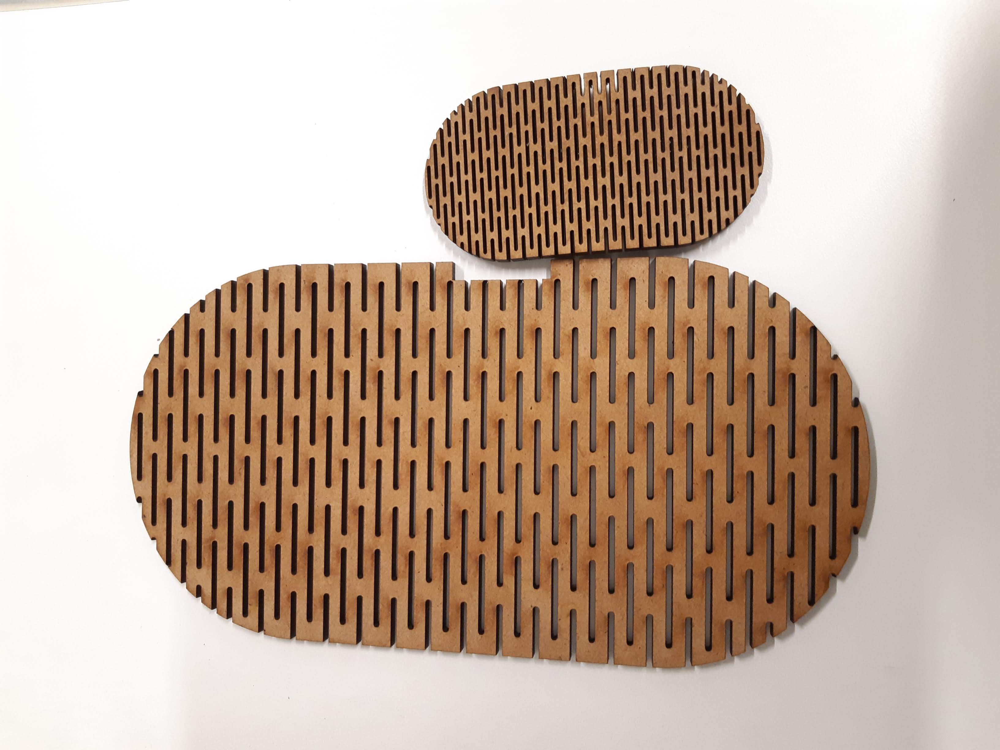
After working in part I of this week's assignment I realized we could build something designing a couple of pieces or even from just one piece with different sizes.
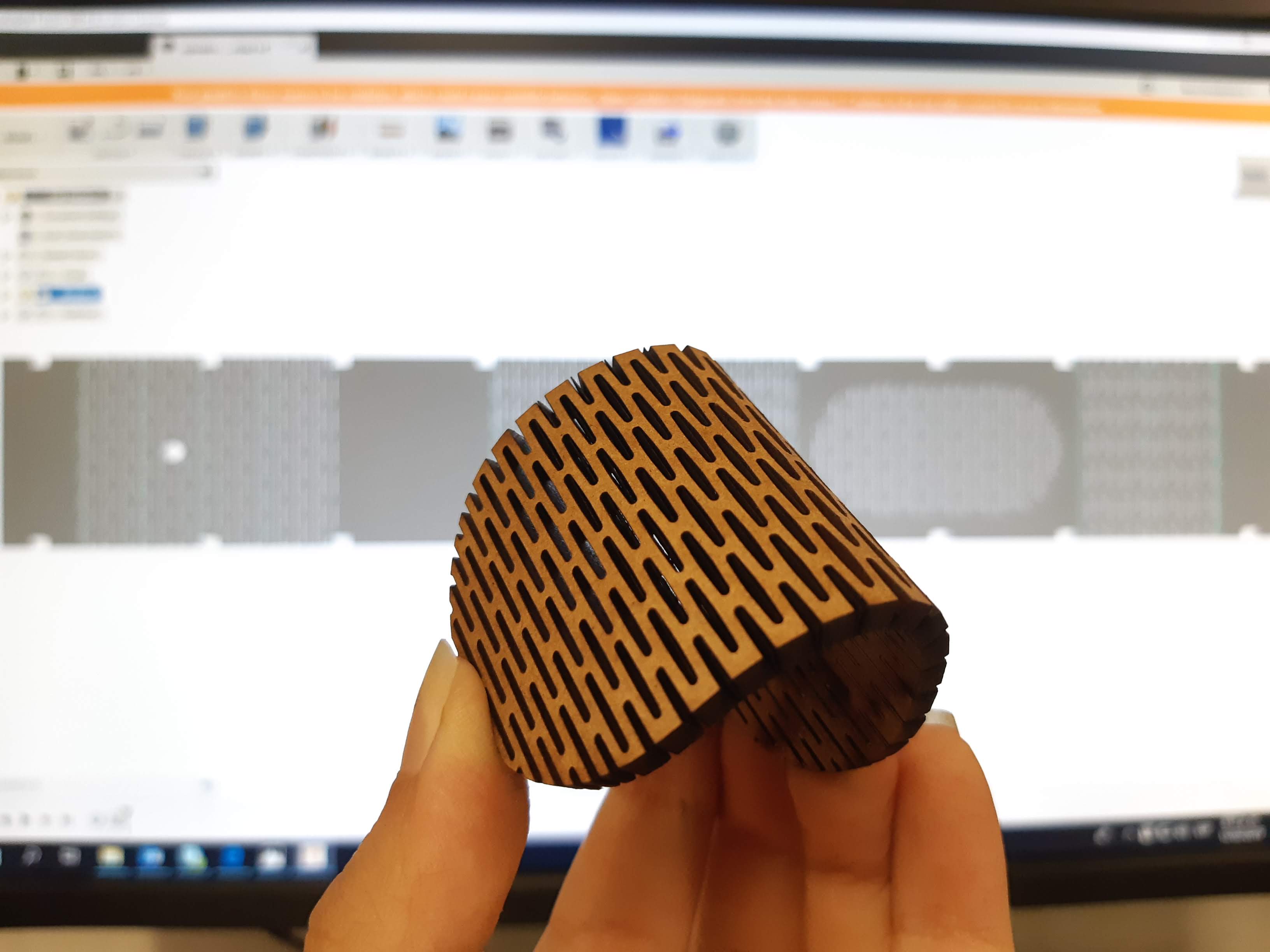
I wanted to go further on this part and work with some patterns for bending mdf.
Designing in fusion
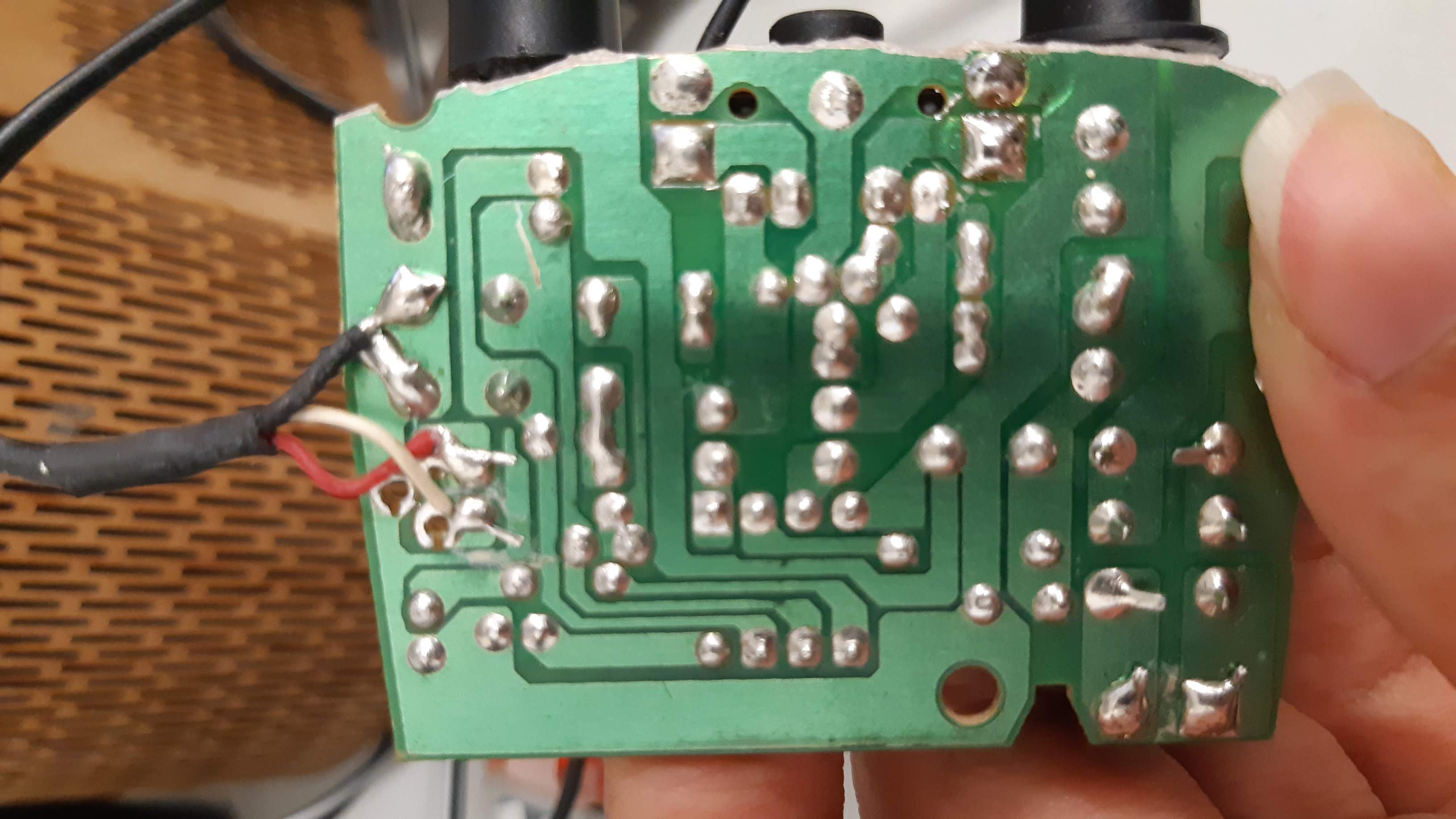
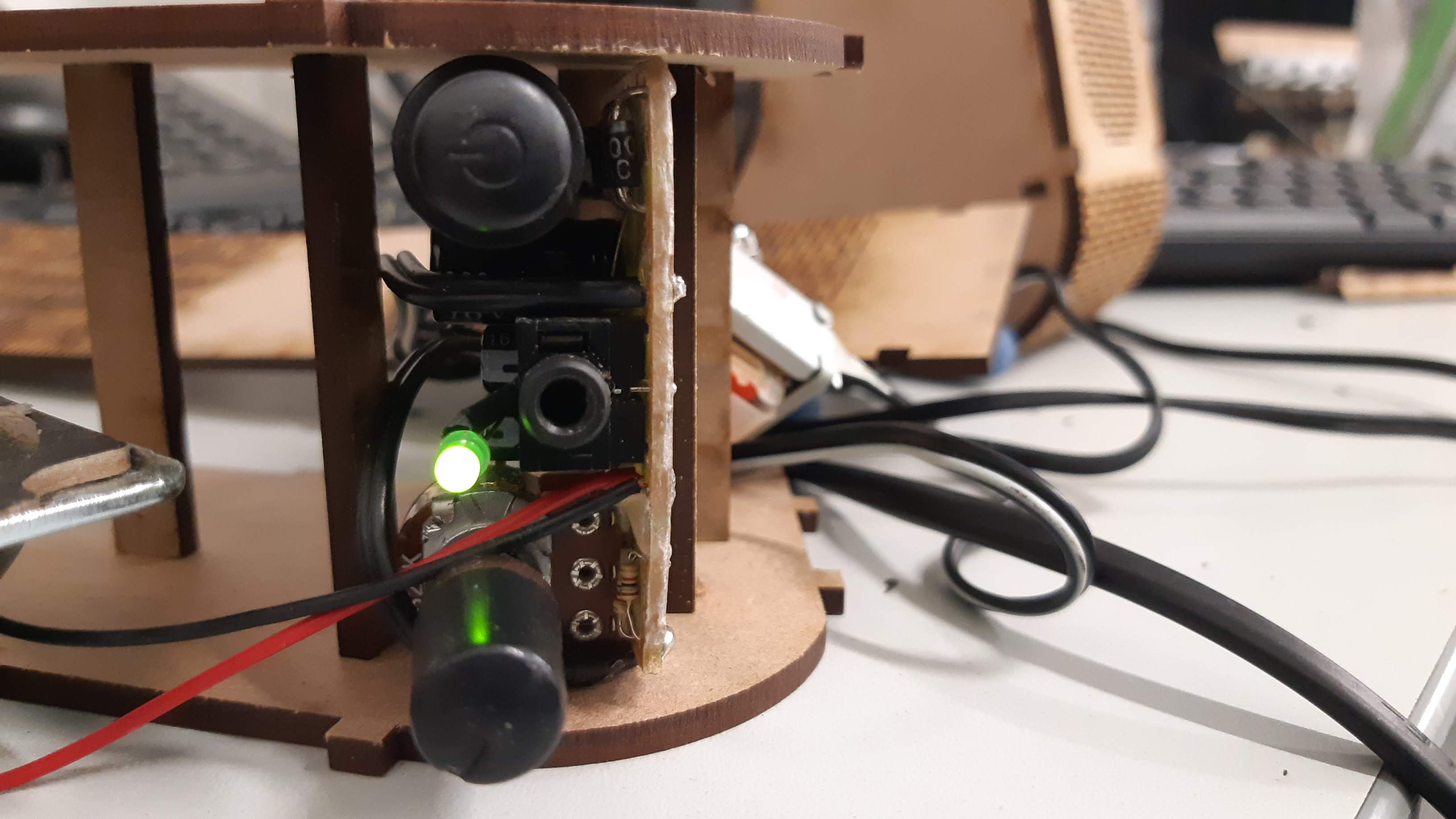
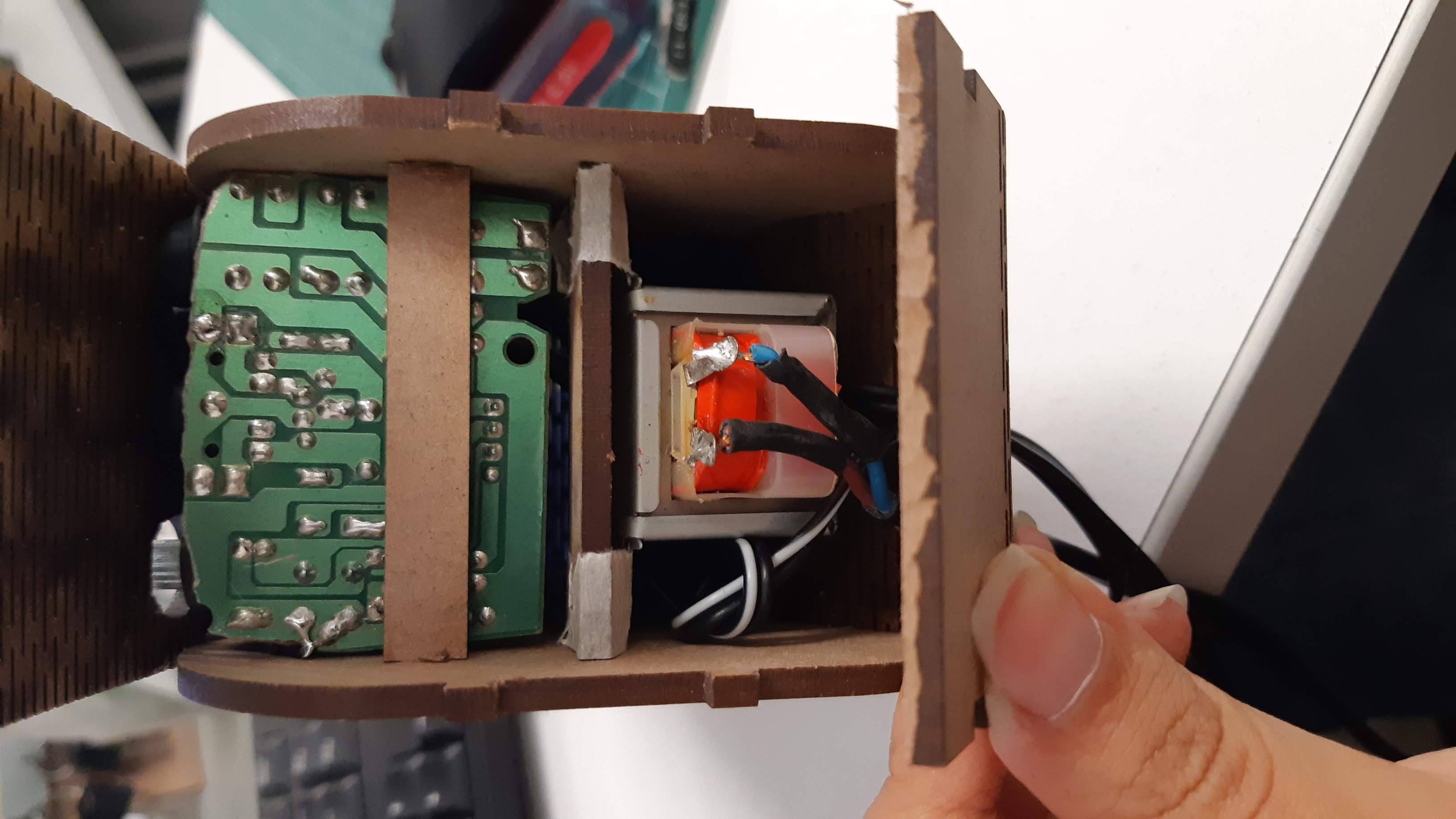
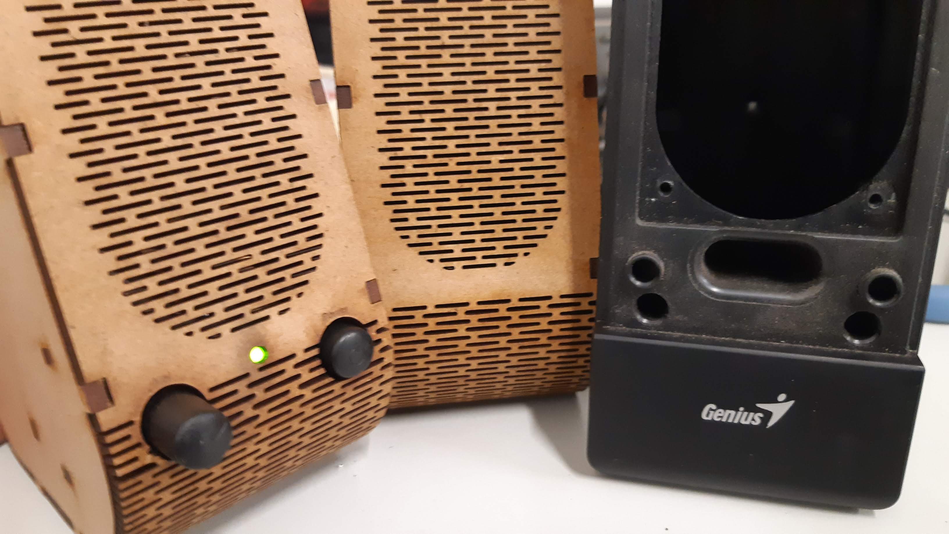
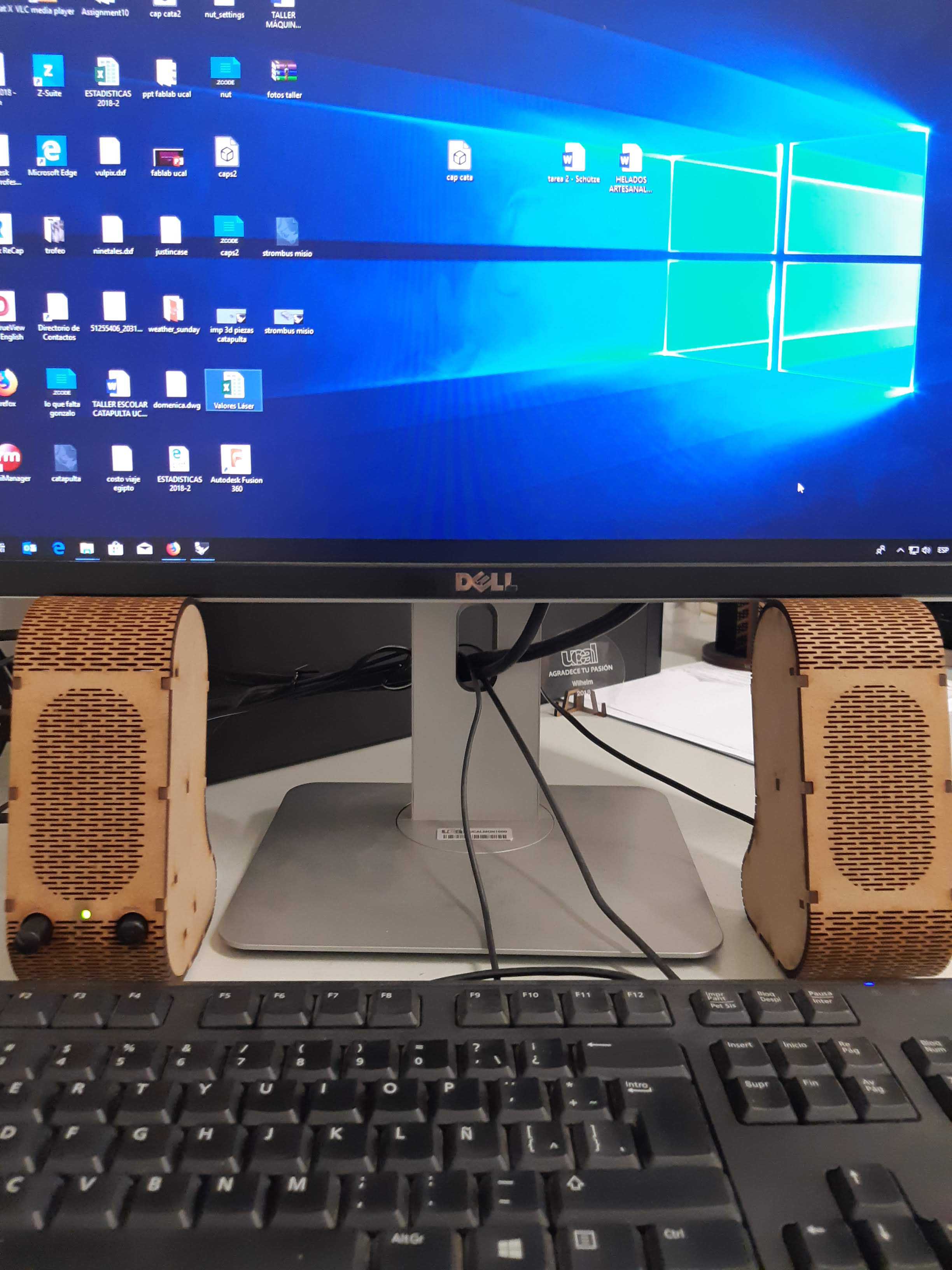
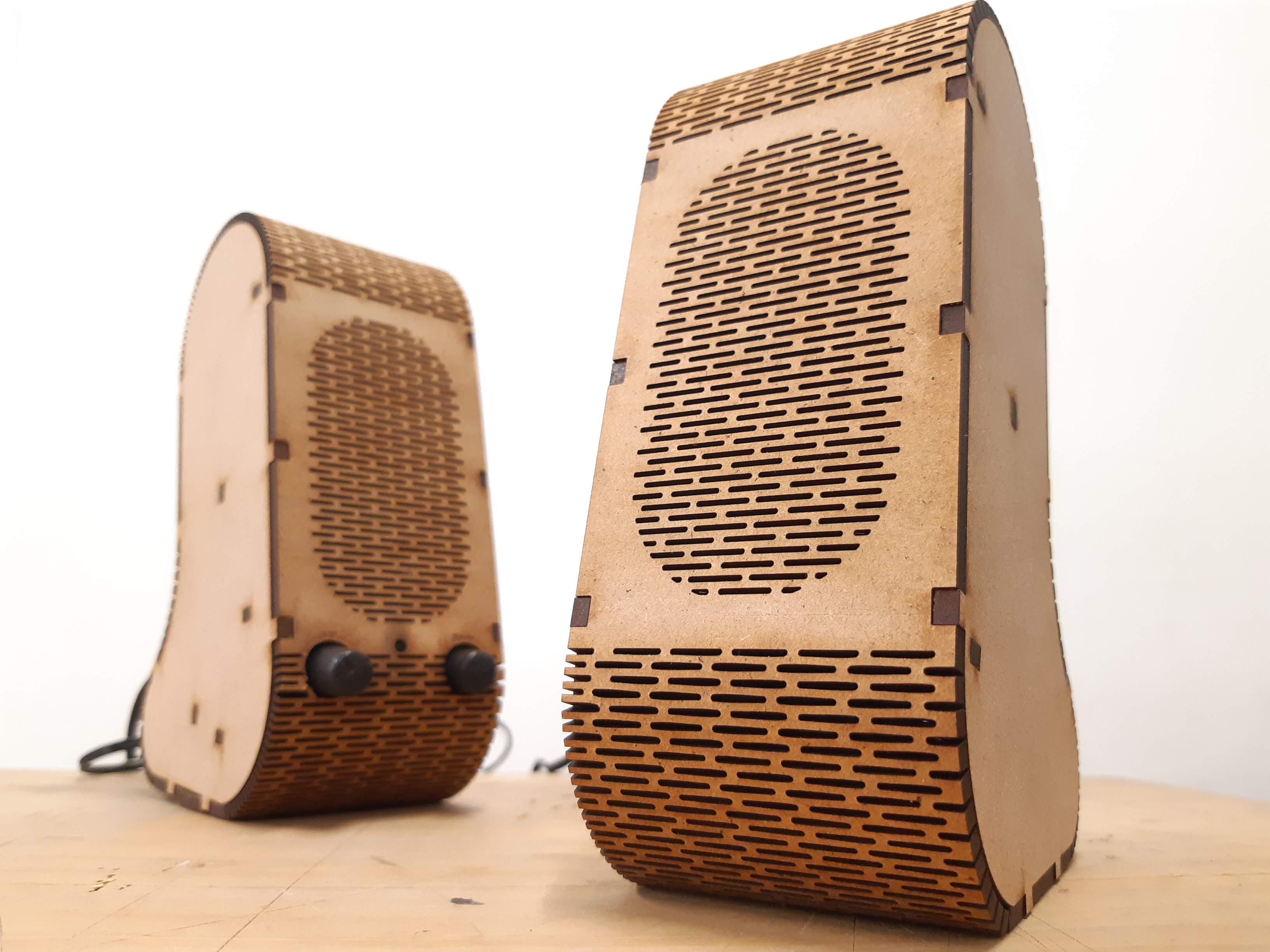
After thinking a while and looking for something to do I found that my speakers were broken and already looking bad, I though that would be a good excuse.
First of all I started with the sketch of the flat parts of the body.
Next I needed to make the bending piece, for that I had to create a metal sheet component, project the profile and extrude.

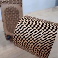
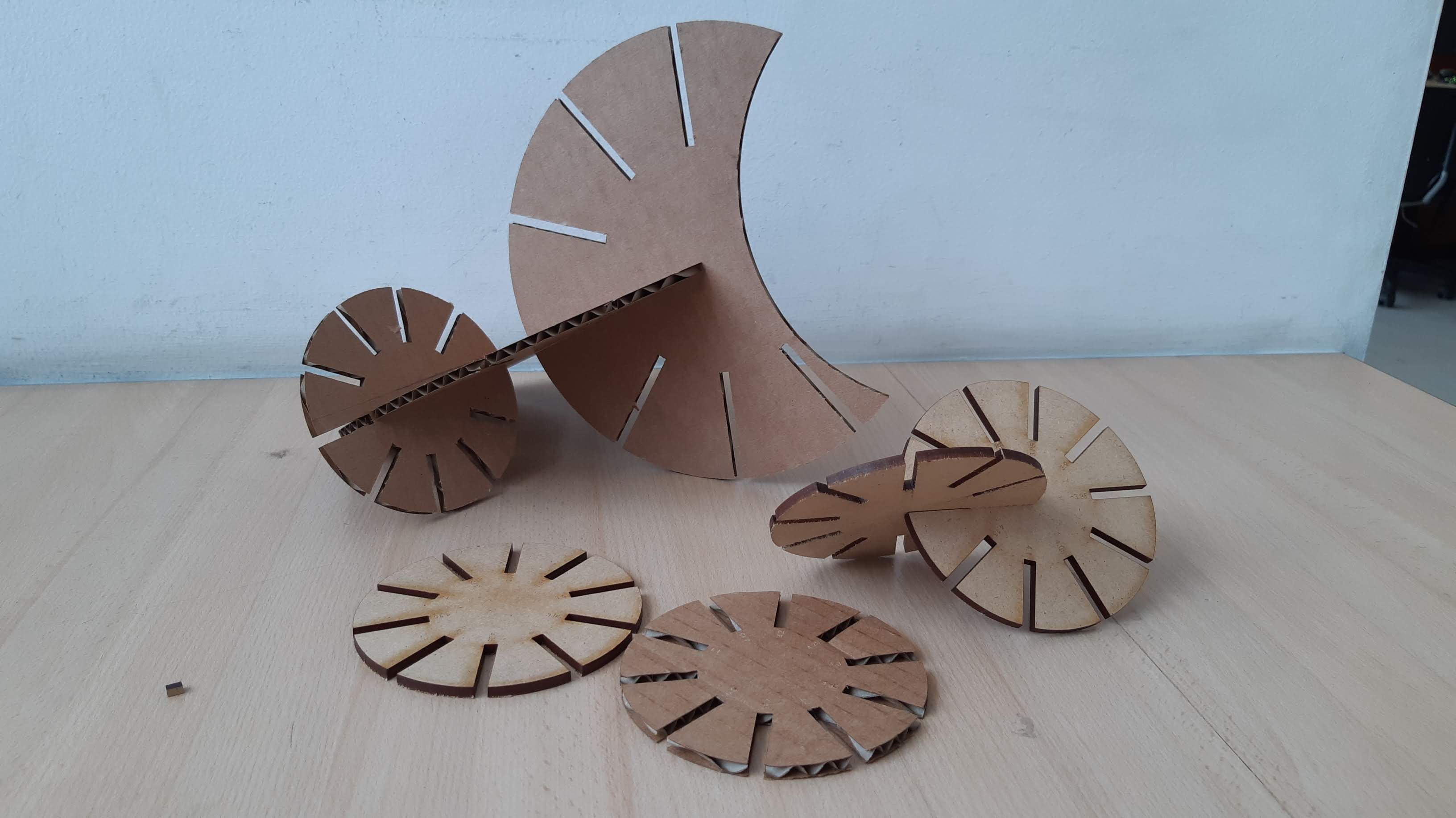
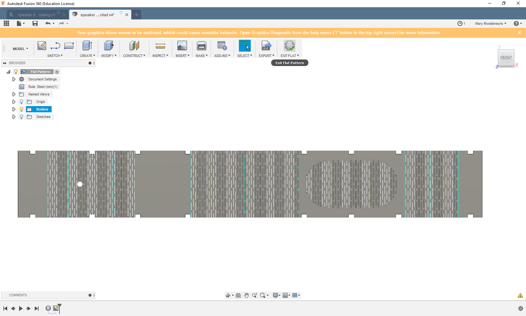
After that I had to work with the piece but in a flat mode. Of course I made some testing first
And the thing about the scale happened to me again
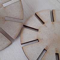
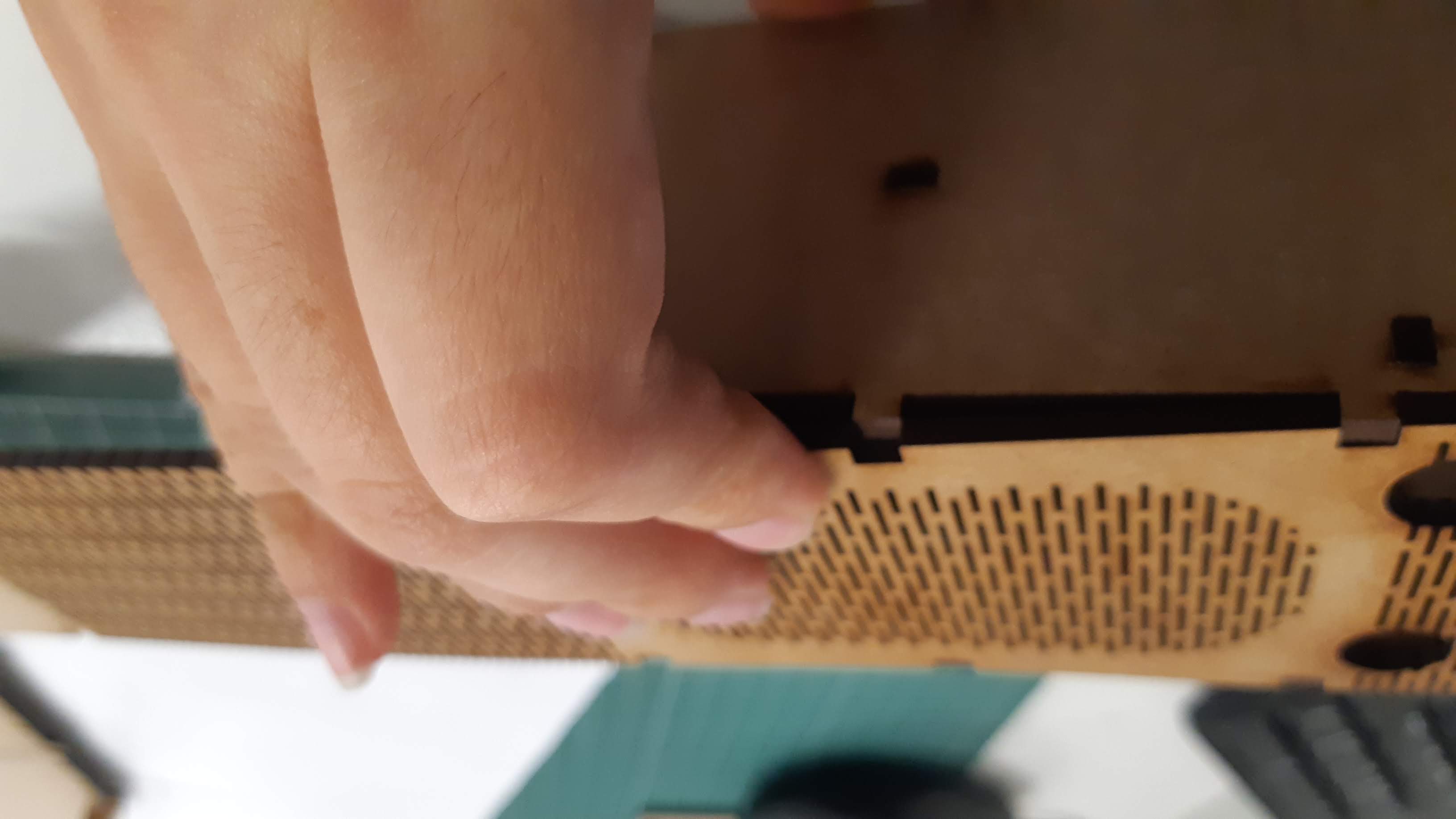
Once I had the flexibility I wanted, I designed all the cuts and gaps according to the profile, checking where it would bend and where the speaker would be.
This actually took really long, the program took it's time to process when making the pattern. It was a bit frustrating, maybe it was the computer I was working with.
Parametric design
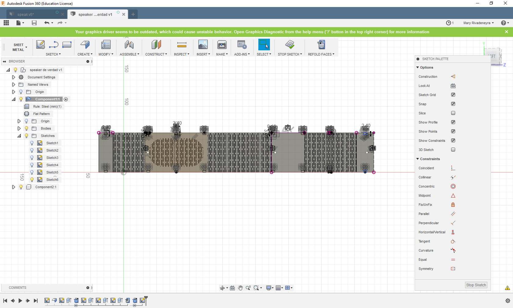
I am working here with a 3mm MDF, and the thickness of the material determines the sizes of the gaps for the joints. I think this is where the advantages of a parametric modeling software are taken.
As you can see in the image below, there are some constraints that could be apply. In the case of changing for example the thickness of the material used, the size of the joints will need to be altered. I applied an equal constraint to the Y axis distance of each gap, this means from the sides to the center of the whole speaker. With this, if I change the size of one of them, the rest will change too.
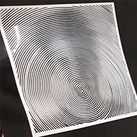
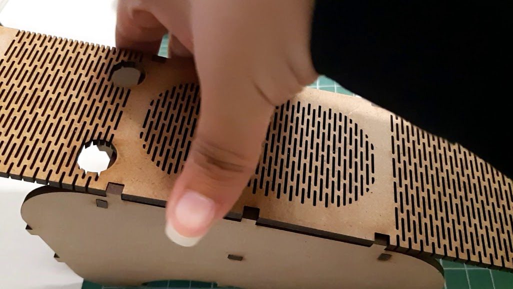
This apply also for the cutting pattern I made to make the mdf flexible.
There are other features we can change in this parametrical design. We can change the material thickness editing the metal sheet and also the extrusion to change very easily the wideness of the final product.
Finally having the pieces I just had to export them and send it to the laser cutter.
Here you can see the final 3d model
To send the file to the laser cut I generated a sheet file.
Laser cut
For this part I used a Trotec Rayjet 300. Process is the same as for the Speedy I used before, the main difference here are the working space (430 x720 mm), and the settings for power, speed and frequency.

Kerf for this machine is also the same as for the Speedy 400, but as I wanted to have a stronger joint to make sure the bending piece wouldn't go back to it's straight position I reduced the gap width for the joints a litle bit more.


This are the parameters used:
Power:99
Speed:1.8
Frequency:1000Hz
Tolerance for kerf:
-0.22 mm
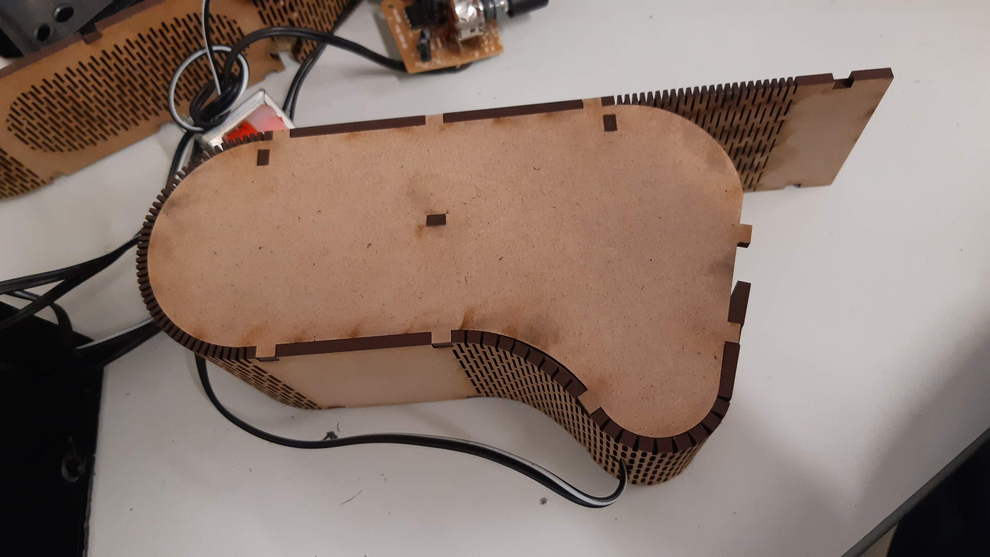
Assembly
Download
You can download the 3d files in any format you want from Fusion HERE