7. Electronics design
This project was interesting. Although most of the parts were familiar for me, tools are renew and have more powerful application. Render it was totally new. The possibility to integrate the mechanical and electronic board at Fusion was exciting.
Group assignment
Roberto Delgado has taught us a class of electronics review. Although it was rocket science for some of us, it was challenging. He taugh us how to use Eagle With our colleagues, we were able to use the multimeter and oscilloscope and a signal generator.
Please take a look at Group assignment part of Silvia Lugo web page.
Assignment:
The assignment consist of: * Redraw the echo hello-world board * Add (at least) a button and LED (with current-limiting resistor) * Check the design rules, make it, and test it. * Extra credit: simulate its operation. * Extra credit: render it.
Redraw the echo hello-world board
The schematic of the hello world board was made at Eagle
Please take a look at the schematic and PCB board.
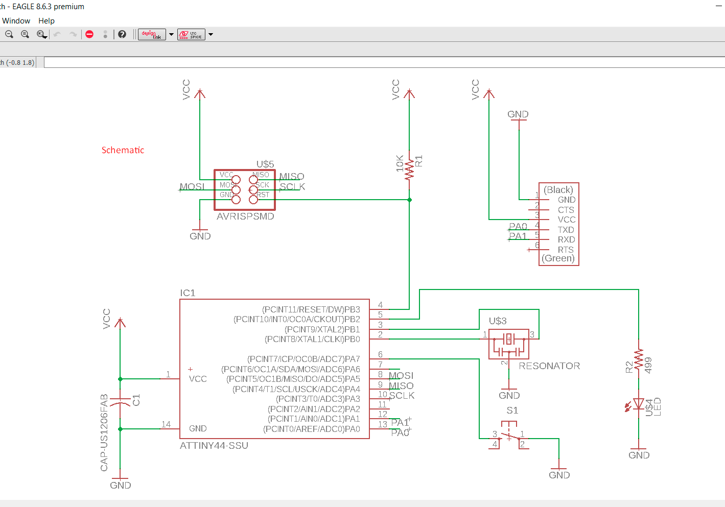
Add a button and a LED (with current-limiting resistor)
Considering Ohm law, I have consider a resistor of 490 Ohm. The current that will be handle on the LED is: 5 V / 490 ohm = 1.02 mA
The push button is drawing towards a PC interface of the micontroller.
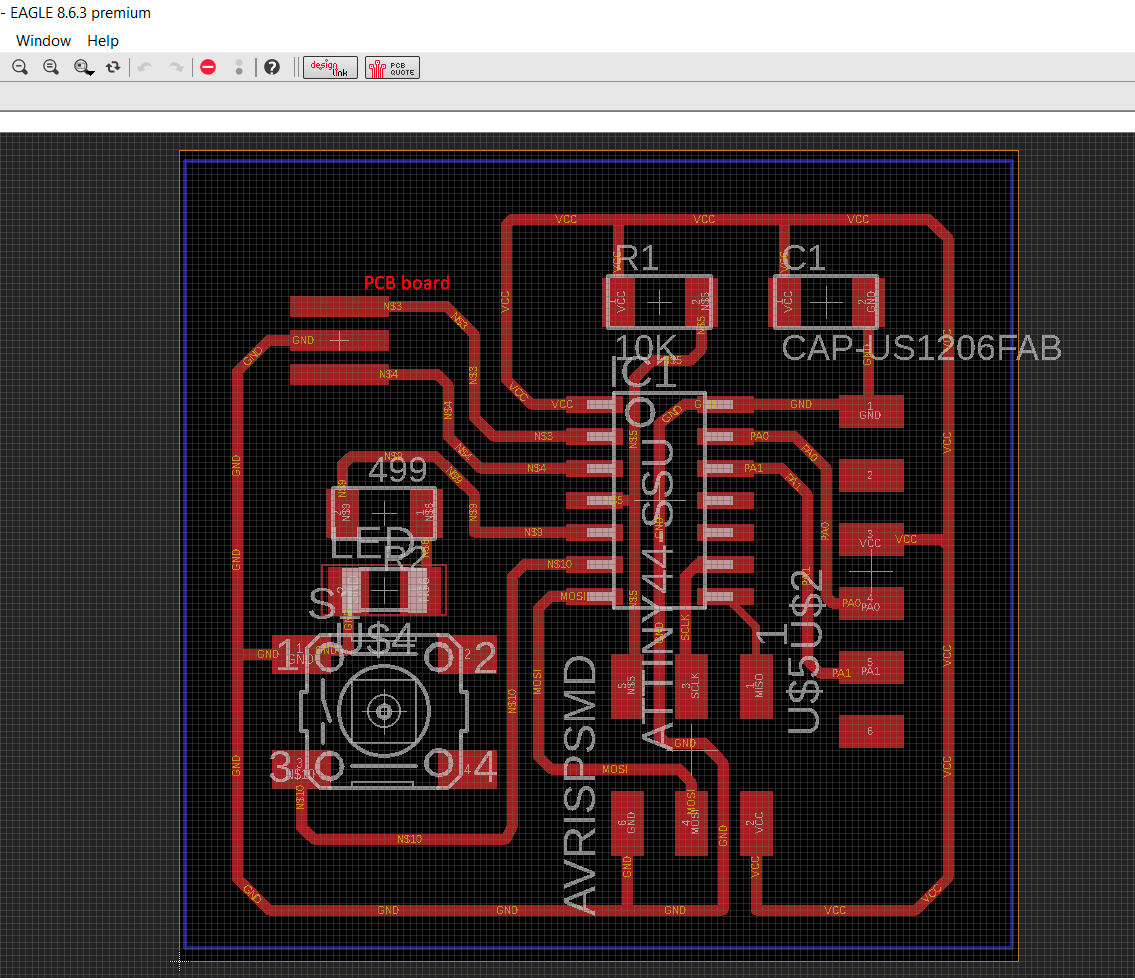
Check the design rules, make it and test it
First of all please consider to check the schematic if there is no errors. At the PCB routing we must consider the width of the path. I consider 6 mm. Although Eagle offer us the option of auto routing, it is not so efficient because it may consider a double layer board. One important tip to take into is to drag the units and see that there is so many crosses between them. After that the routing is made manually. I enable the grid, so it will help me to route the routes. Eagle offer us the option of handle different layers. I consider a layer for routing and milling and another one for cutting.
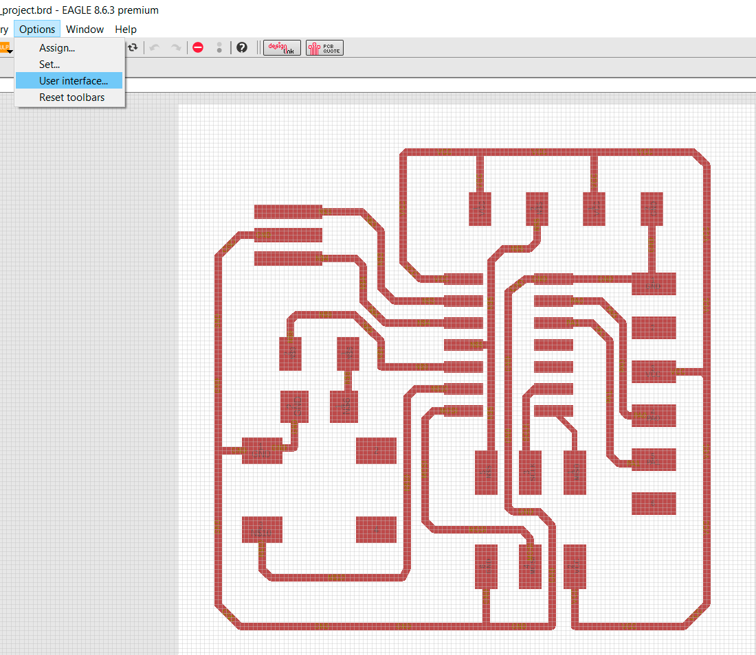
Once done, in order to continue with the milling we need to export the PCB file to an image. If we do not change the background color and select only monochromatic the PCB will be like:
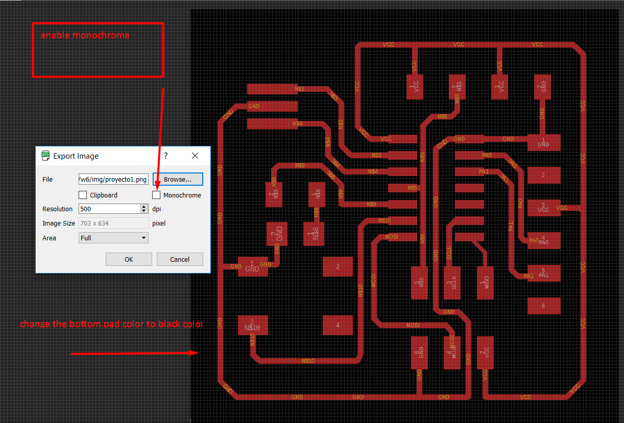
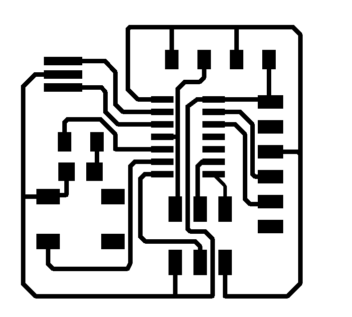
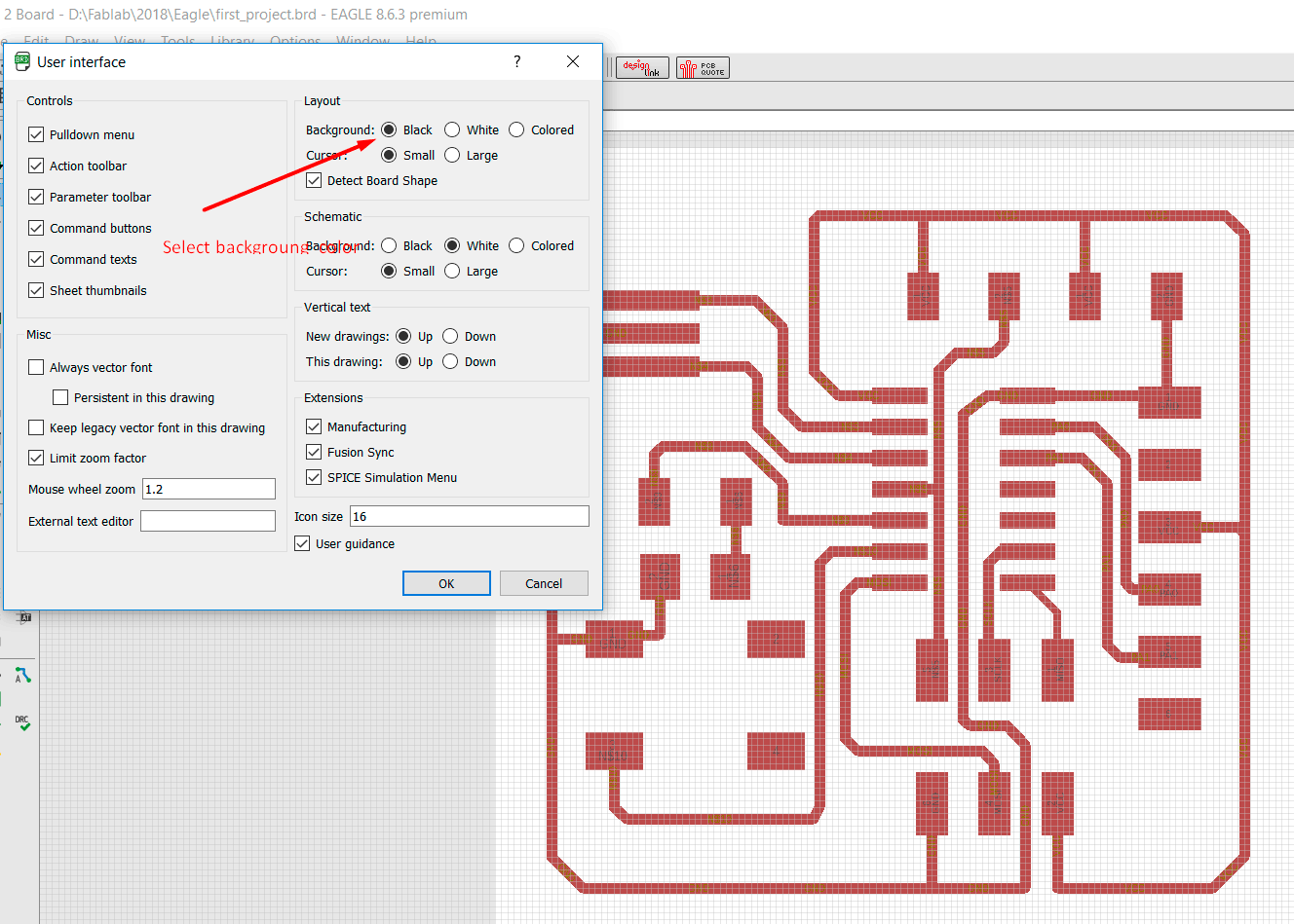
If we mill it we will carve the paths!! which is not the deal at these moment. So, I had changed the background color to black.
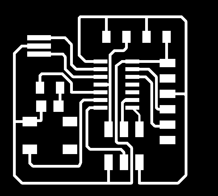

Now you may see the correct image to use at ROLAND machine for milling and cutting.
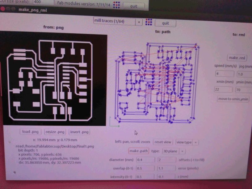
Once milling and cutting is done, with all the care handle in this project, I had done these part three times because I had problems at fixing the copper board to the MODELA. If it is not well fixed some paths can be cut and made the project useless.
Prior to solder all the paths should be check with the multimeter for continuity according to our PCB layout, then you can solder the component at the board. Tip.- Put the flux just on the board were the component will be place, you may see better results.
Important.- Once you finish to solder a component it is a good idea to check the continuity, otherwise you may have to external connection like:
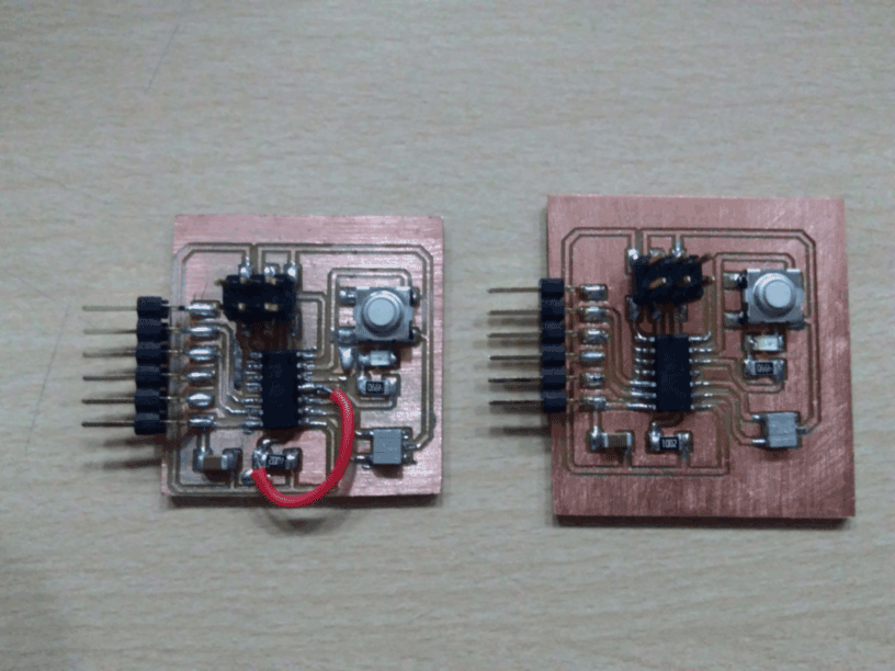
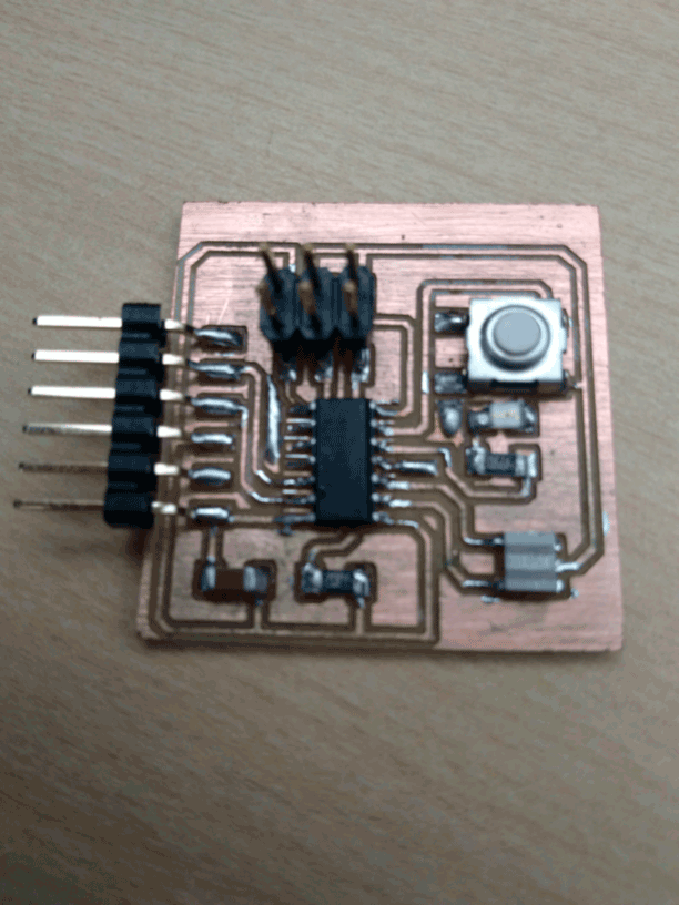
Please see mine last board (second one)
You may download the boards here
Program the hello-world board
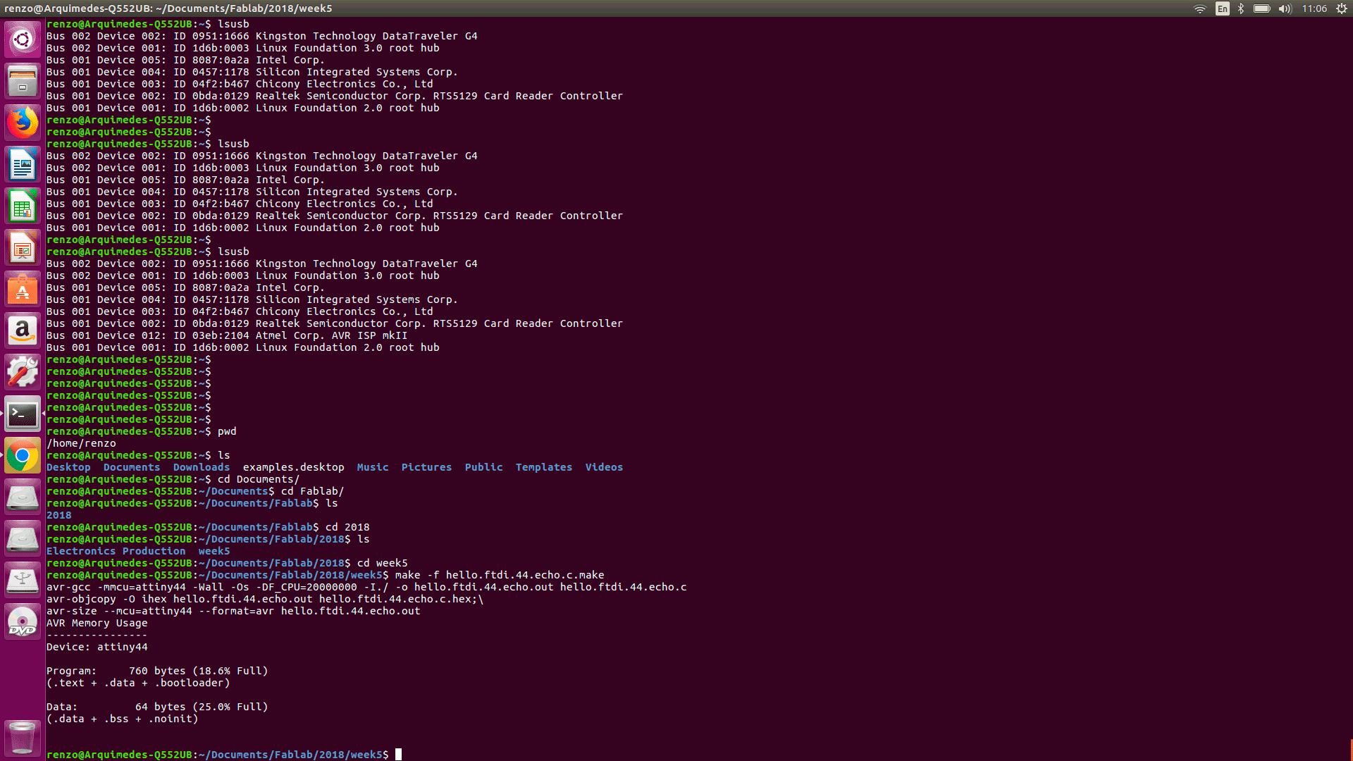
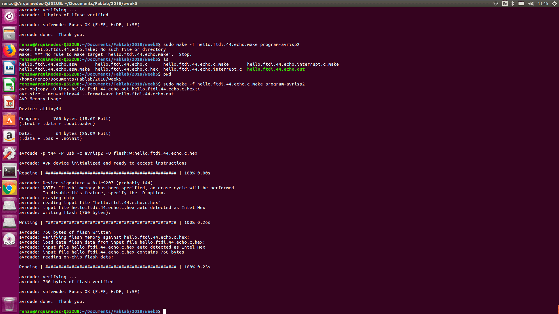
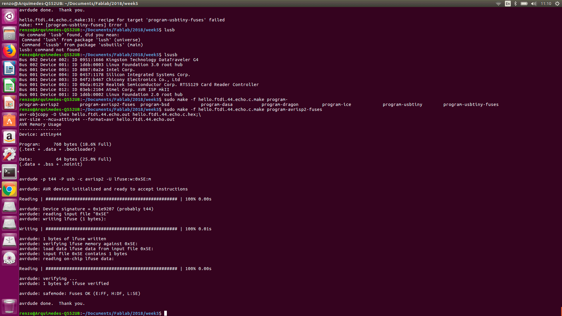
In order to program the board, first I had download the asm files and c files of the FAB web page. In order to program the microcontroller please follow these programming steps. Please take a look at the steps follow by myself. I program the microntroller with and AVRISP II board.
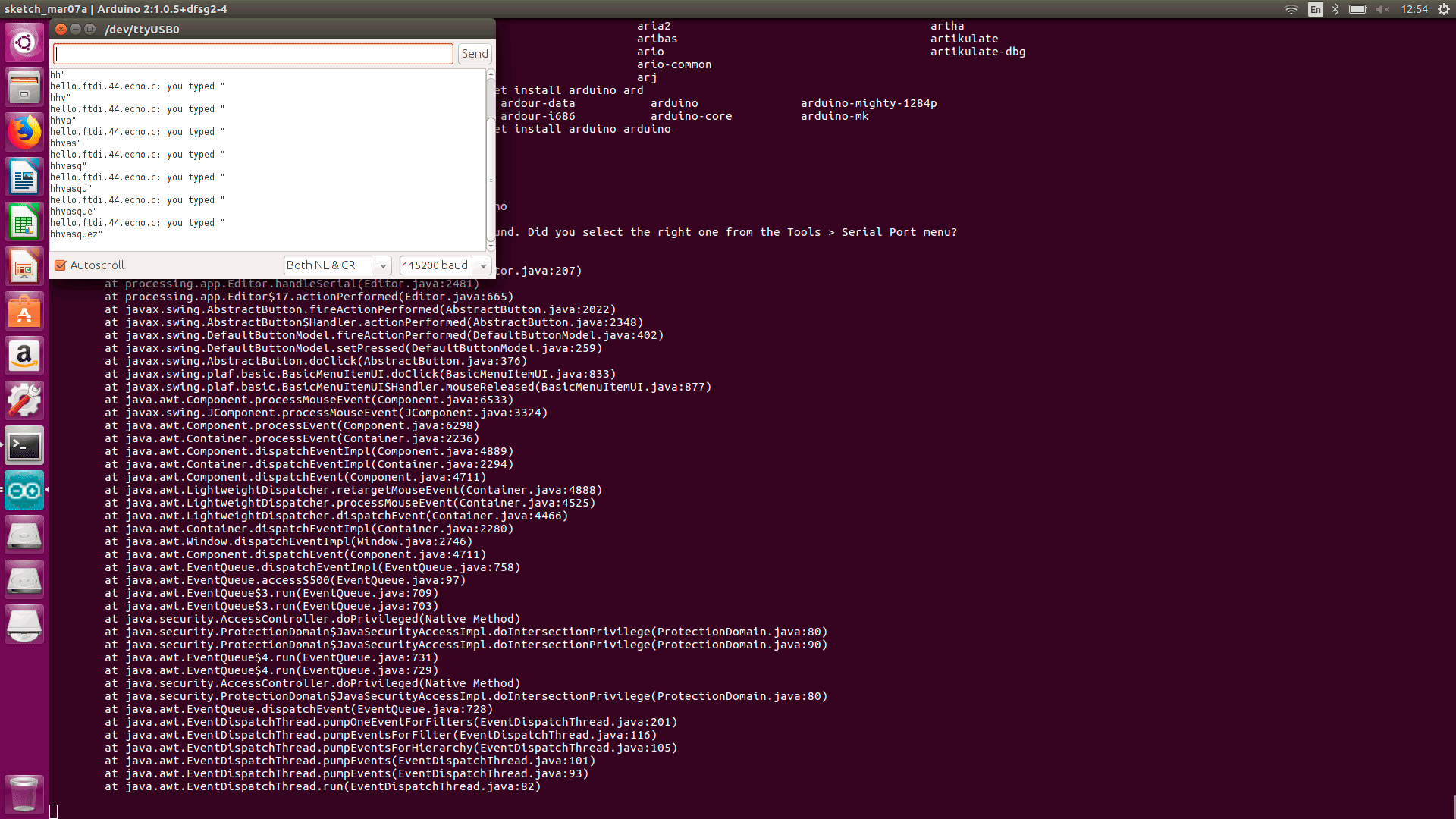
Finally I connect the FTDI cable to the serial port of my computer towards the board. By the serial monitor of Arduino I was able to see the outputs of the script at the microcontroller.
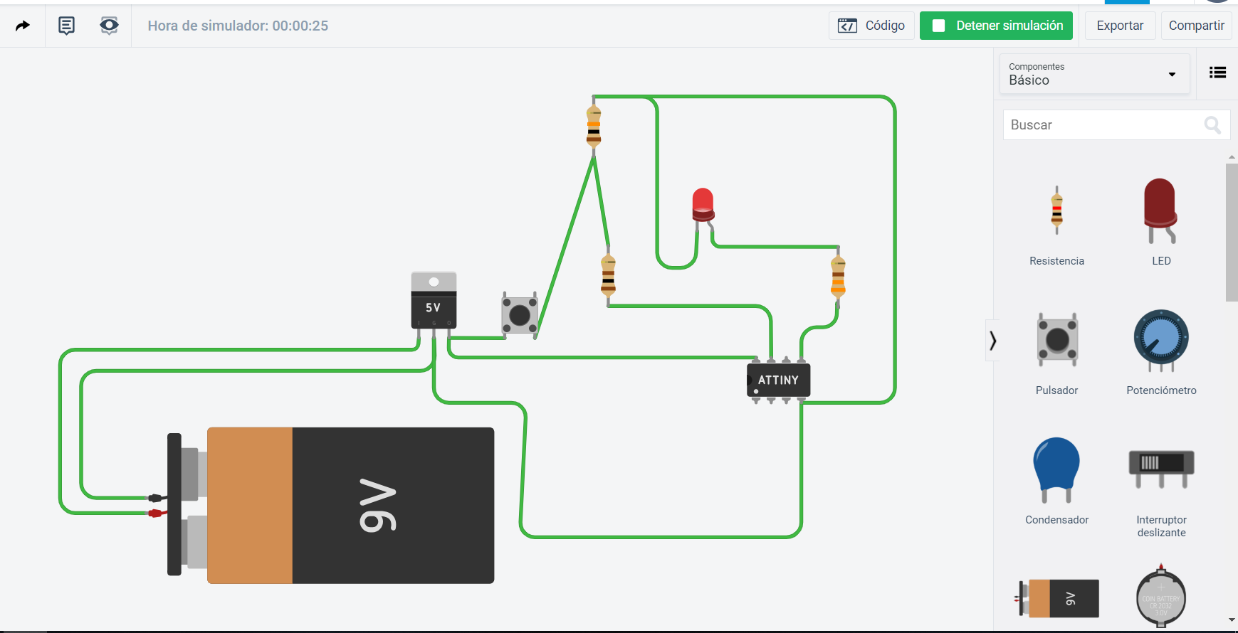
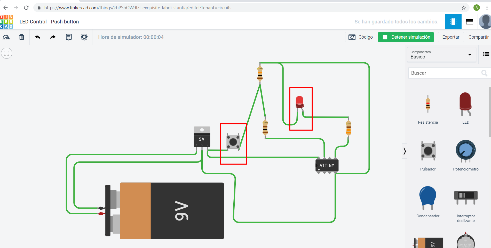
Simulate its operation
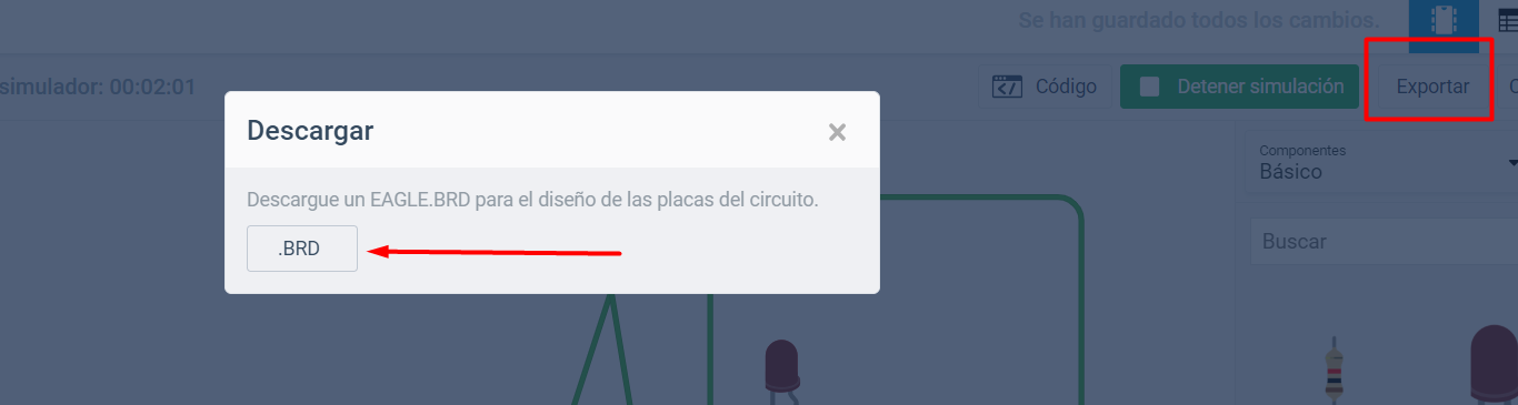
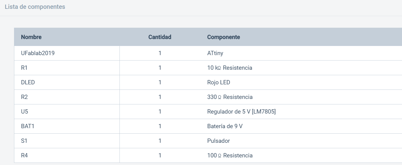
This opportunity I had used TinkerCAD for the simulation and programming of the board. I was really exited because I was able to create a circuit diagram and simulate it. The good part from TinkerCAD is that you can test your scripts and see how it works. Another important part is that you can export the BRD to Eagle and edit it. I have not seen if it is possible to put SMD components, for the moment I have only check the traditional components. Finally you can have the list of all the components used.
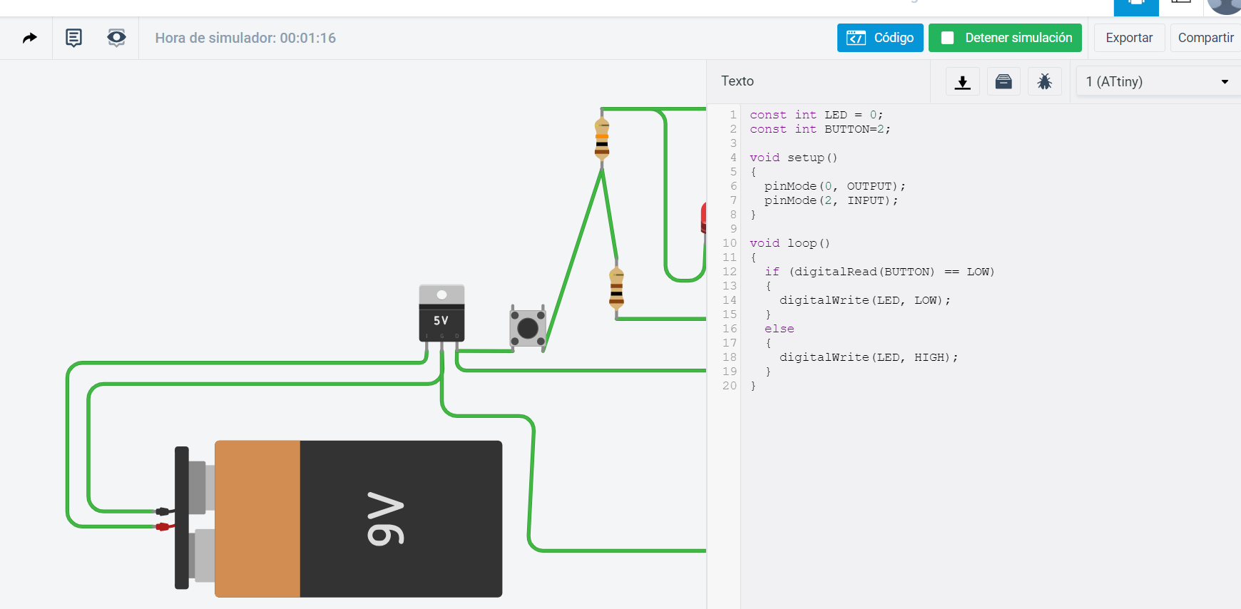
Programming was interesting. I was able to write by text the script. Please take a look to my script.
const int LED = 0;
const int BUTTON=2;

void setup()
{
  pinMode(0, OUTPUT);
  pinMode(2, INPUT);
}

void loop()
{
  if (digitalRead(BUTTON) == LOW)
  {
    digitalWrite(LED, LOW);
  }
  else
  {
    digitalWrite(LED, HIGH);
  }
}

Render
Nowadays that Autodesk handles Fusion and Eagle. I got impress about all the possibilities to do with it. I have follow this tutorial made by Autodesk. It is easy for reading and very comprehensive material.
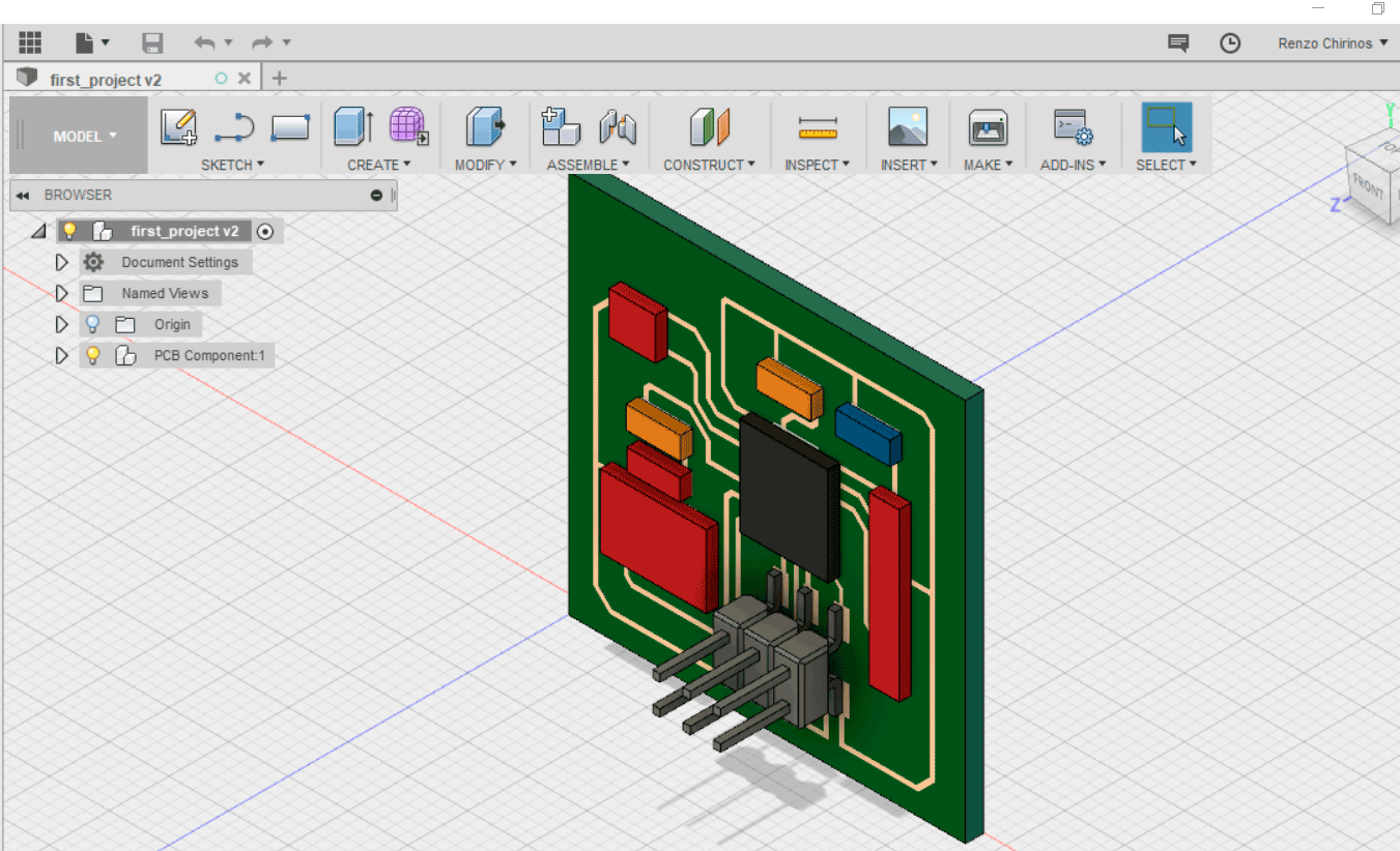
After doing all the steps you may see your board like:
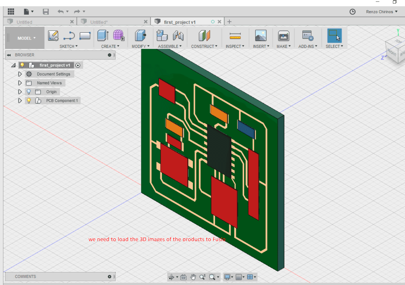
You may see that the components are not like they look in the real world. That it because our fab library do not have a 3D model of the components. I have loaded the 3D with STEP extension files from:
3D CONTENT CENTRAL by Dassault Systems. Other models were download from Digikey.
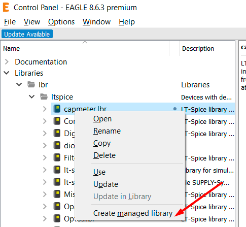
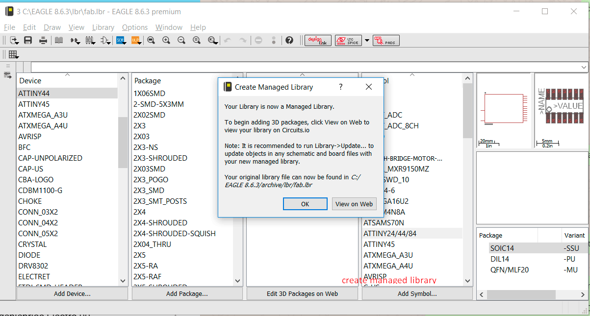
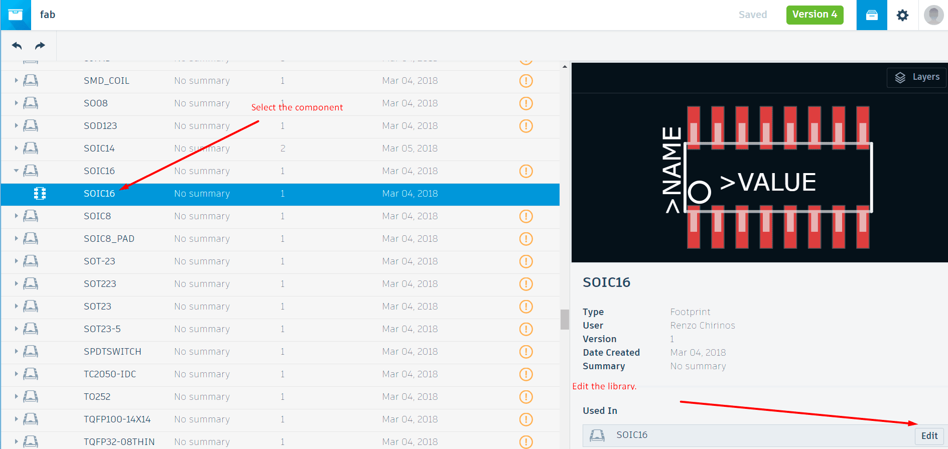
The first step is to convert our library to a managed library, once I create it, I was able to edit it at the Web.
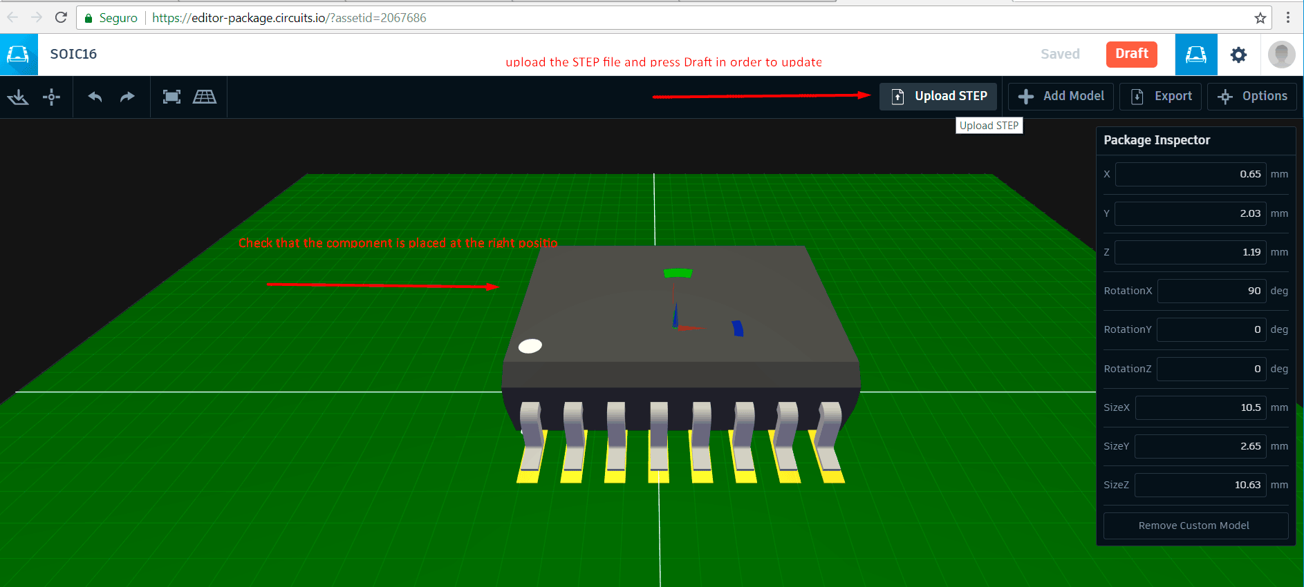
You may be ask for your Autodesk account. It opens the Library editor. Please select the component and clic the Edit button. Then proceed to load the STEP file, please consider the unit is placed on its correct position.
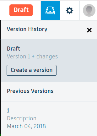
Then select the Draft button and create a version. Otherwise it will not update on the Eagle library since it will be keep as draft.
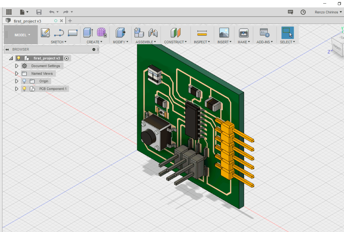
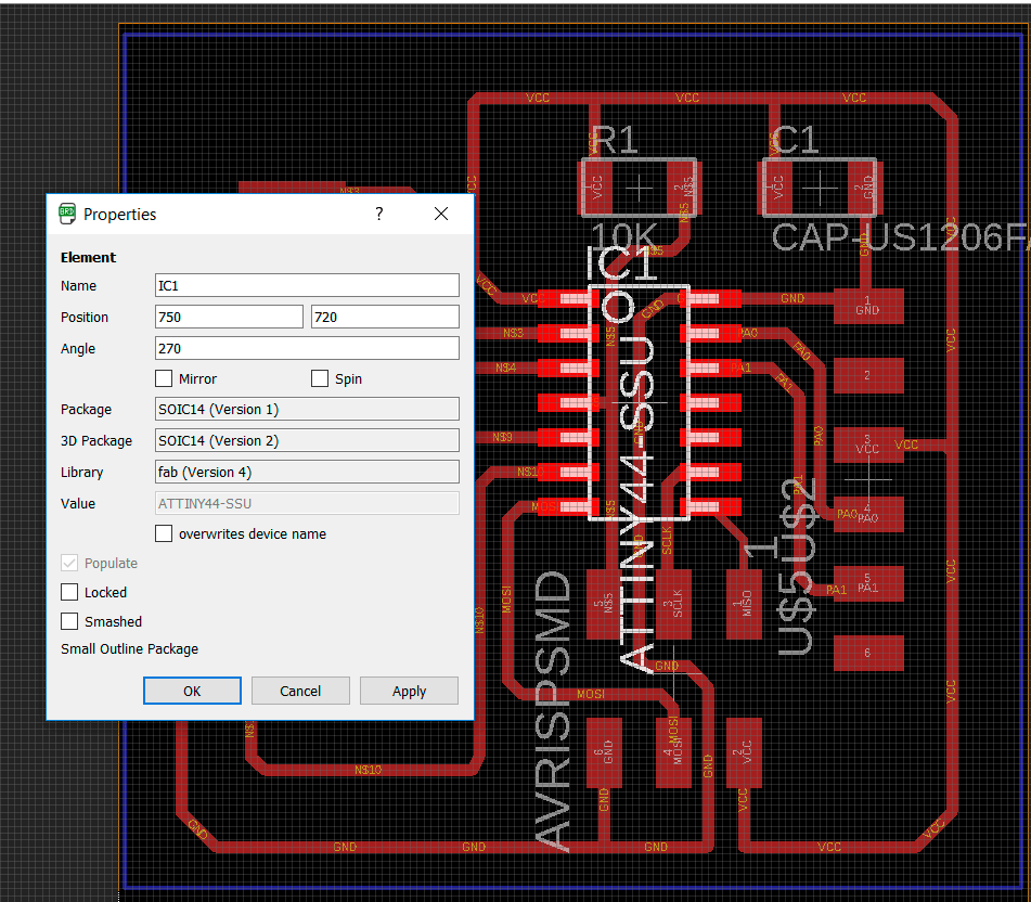
Once you have finish the upload of the STEP files you have to update the library at the Eagle control panel and the schematic. Please select a component and you may see if it has update the version.
 Finally once you finish you may synchronize the Eagle PCB with Fusion, using the same tutorial steps as before.