11. Input devices
Individual assignment:
Measure something: add a sensor to a microcontroller board that you have designed and read it.
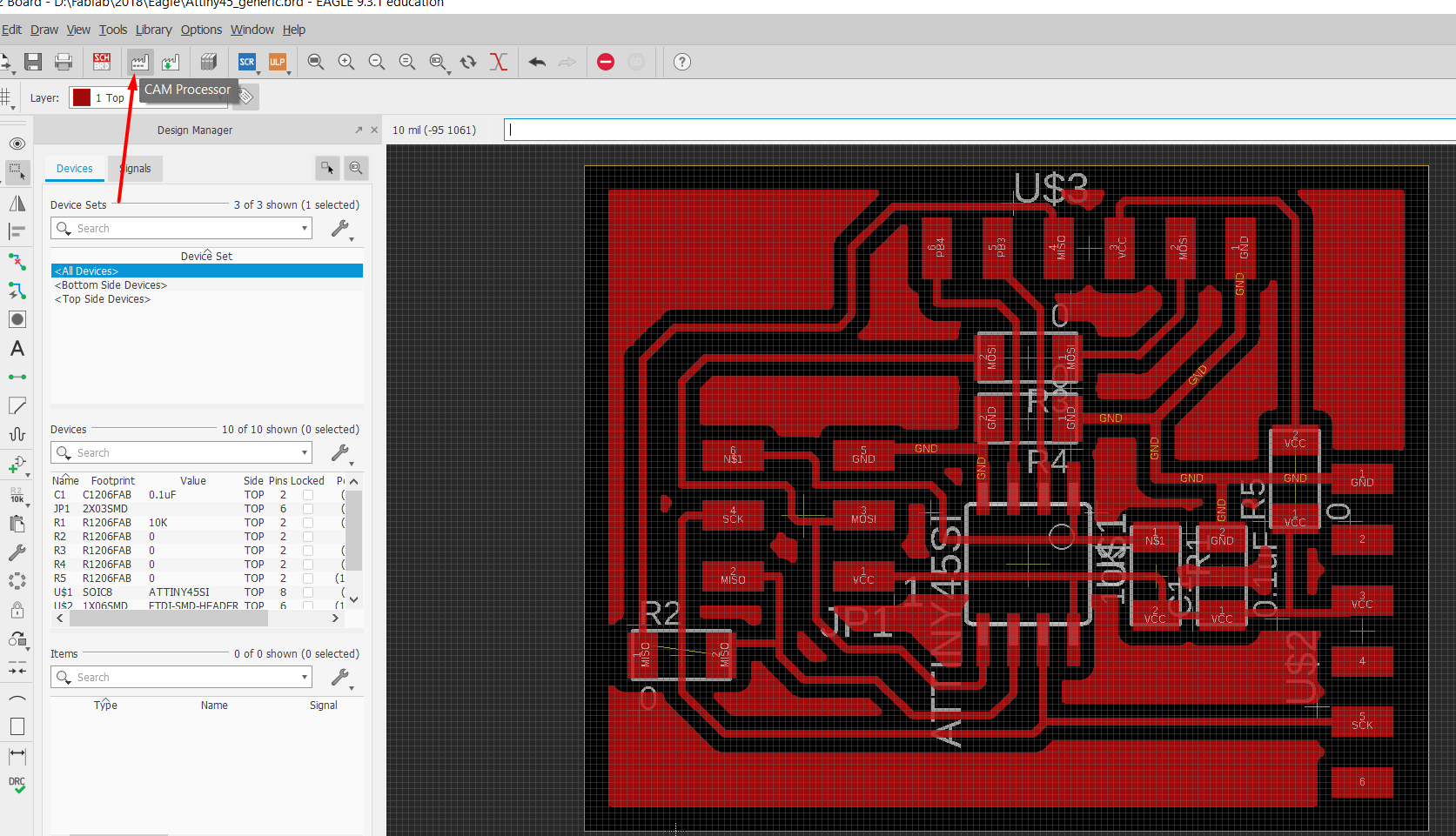
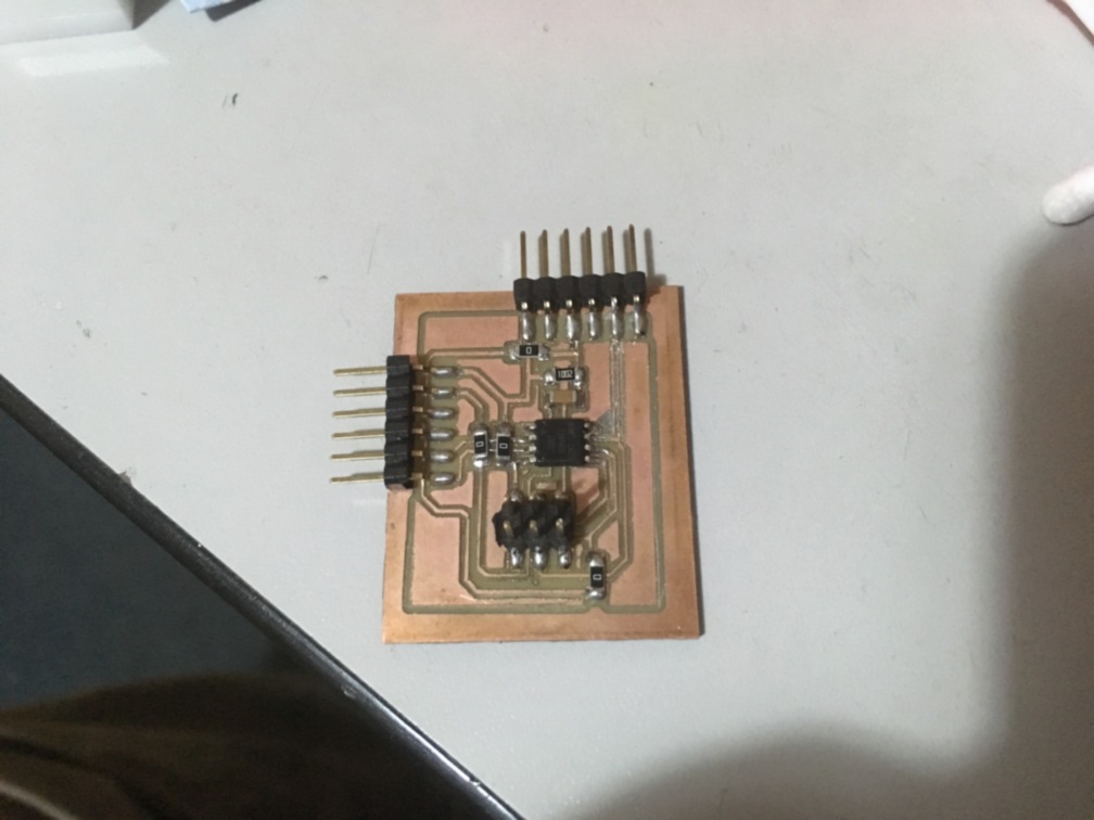
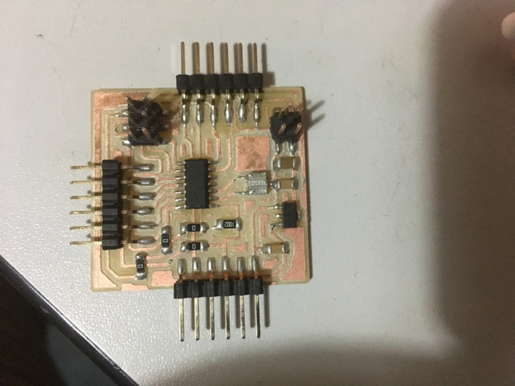
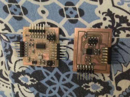
For these project I want to user several input sensor like distance, motion. In order to complete the project I built a generic board with a Attiny45 and ATtiny44.
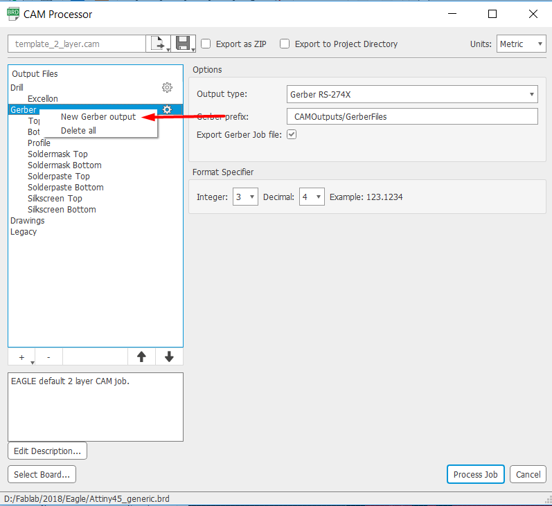
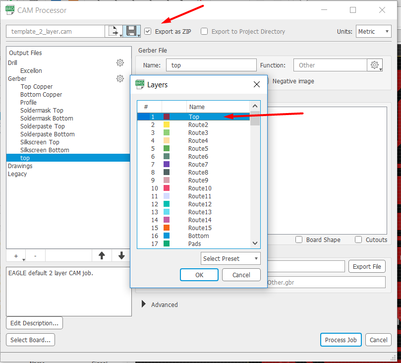
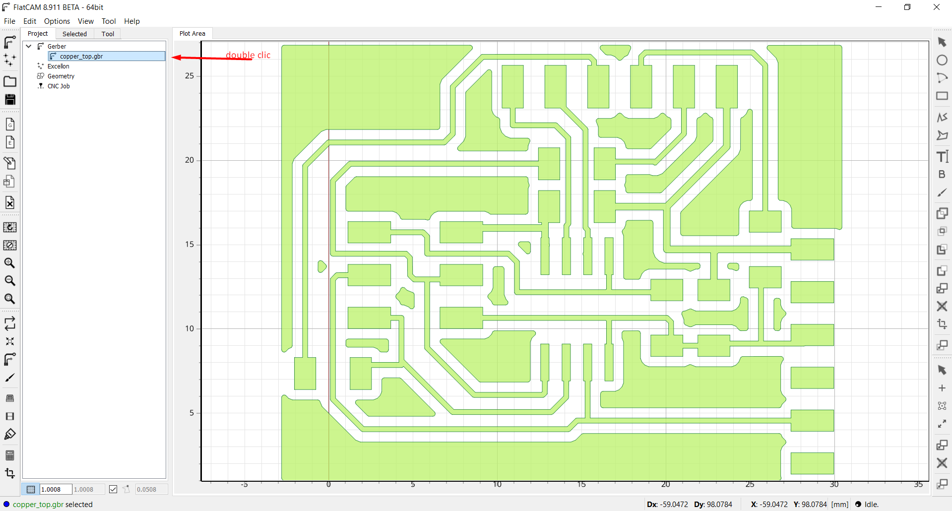
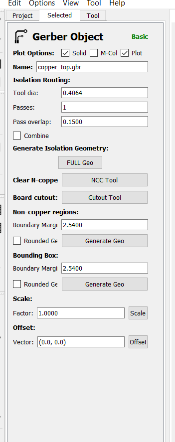
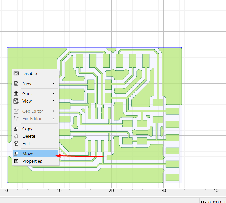
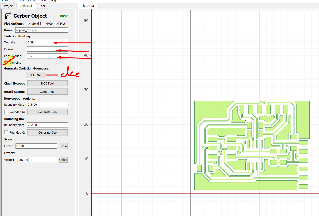
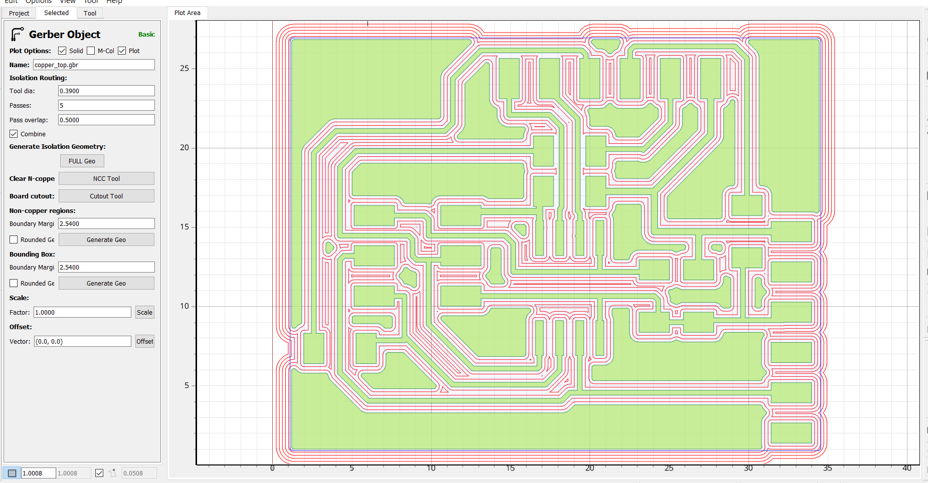
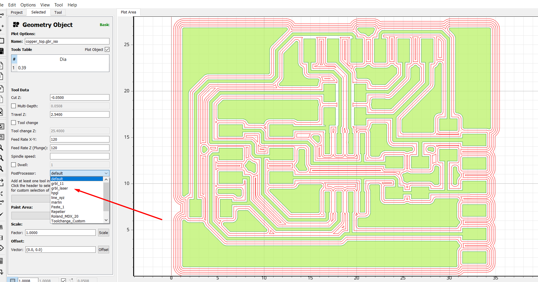
For these part I tried to use the Gerber tool of Eagle. Please see the following pictures. They are at sequence.
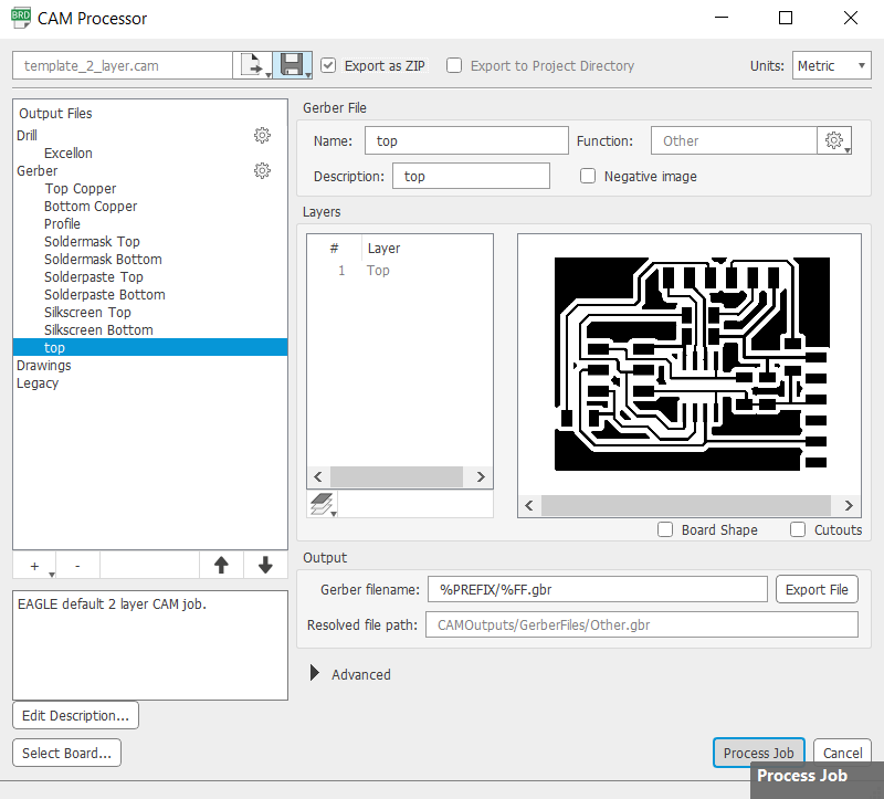
Later on, you may process it at Flatcam so the CNC can execute the G-code commands.
For these project, since there is a need to have a FTDI cable. I had built one. Almost all the coming projects need one, in order to program, give power. I used a FT232RL chip. The good part of these chip is that it has an integrated 3.3V level converter. you may use it to read 3.3V or 5V sensor, you just have to change a jumper at the board.
Design was made according to the datasheet. I choose the UART design. I used the DTR port instead of the RTS port. This is because the DTR port allows to do auto reset. If the board is not recognize, please consider to install the driver. You may download the schematic and board here. I could not get a smd polarized capacitor. I used the old ones, drilling the board was needed. Something to consider is that FTDI without a polarized capacitor does not work. I am not sure why. Promise to update at future weeks.
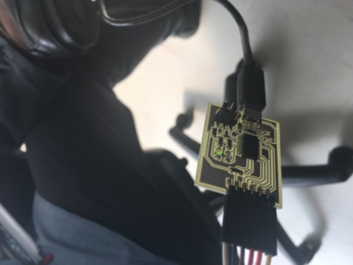
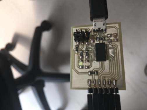
In order to work with it I made a couple of generic boards as mention before with Attiny44 board and Attiny45 board. The idea was to use a single board for this coming weeks.
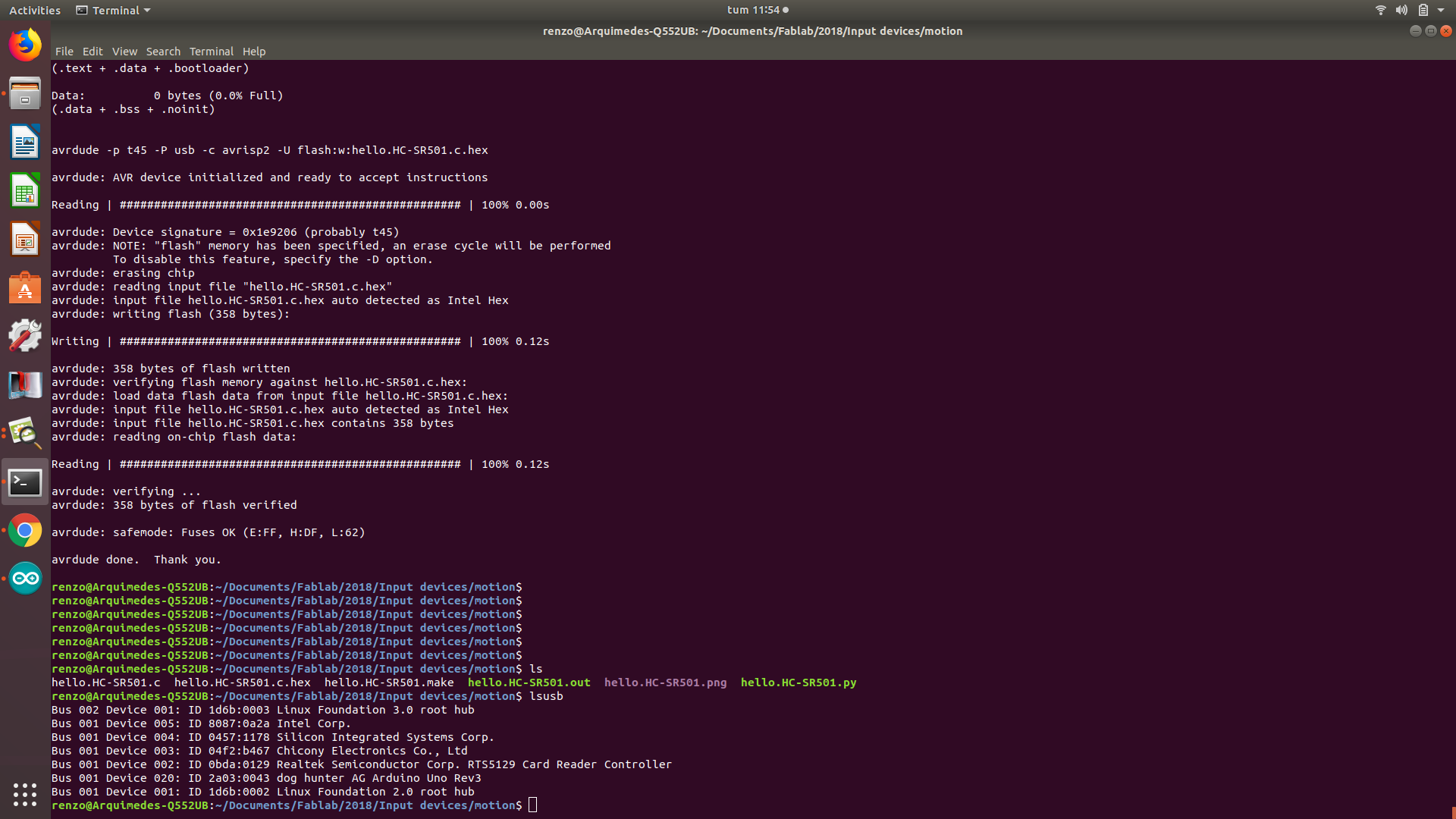
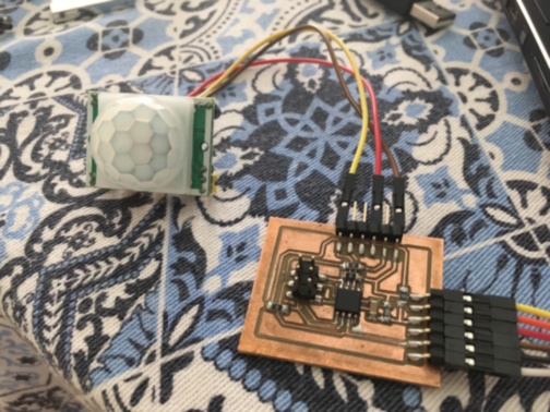
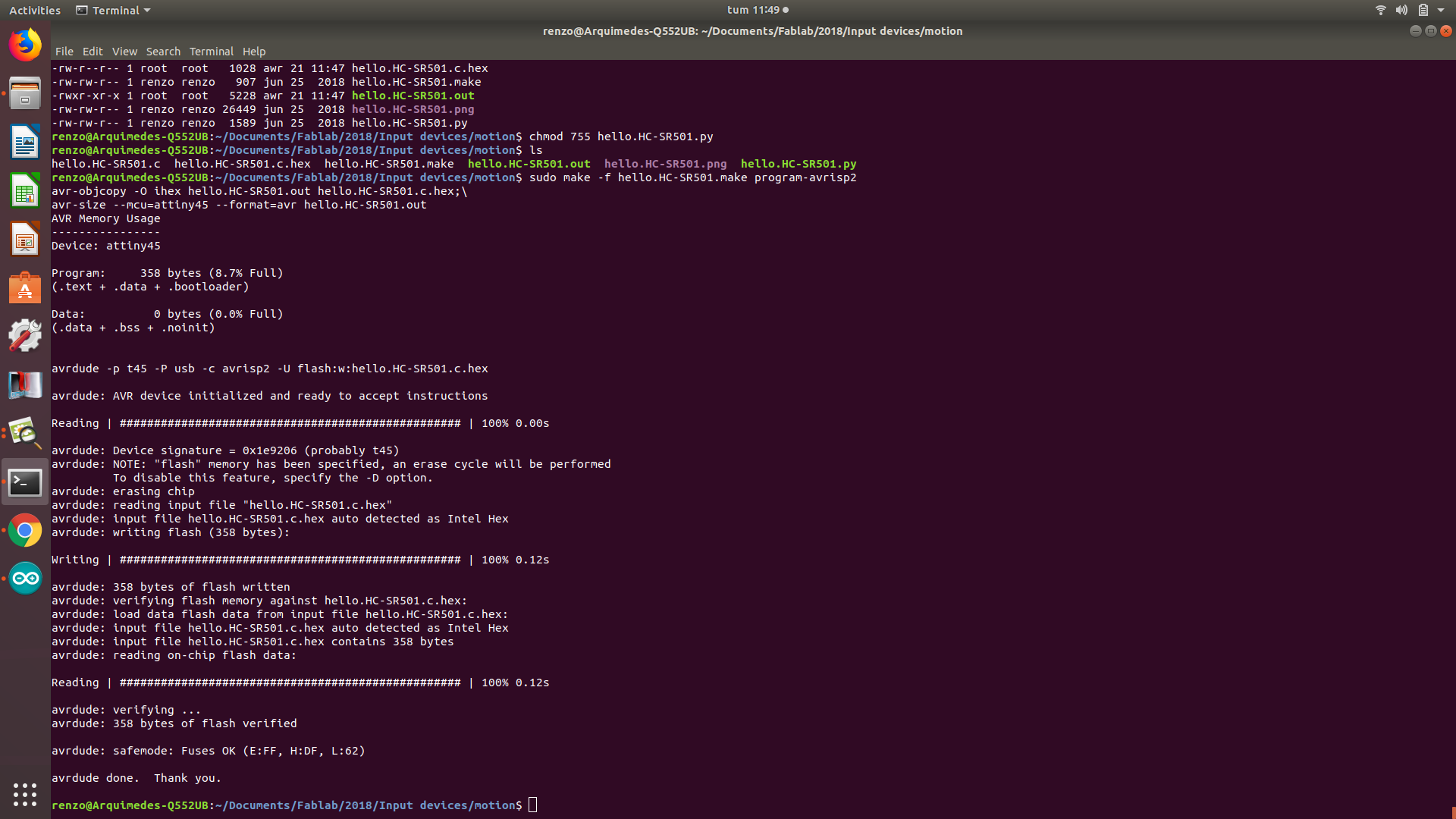
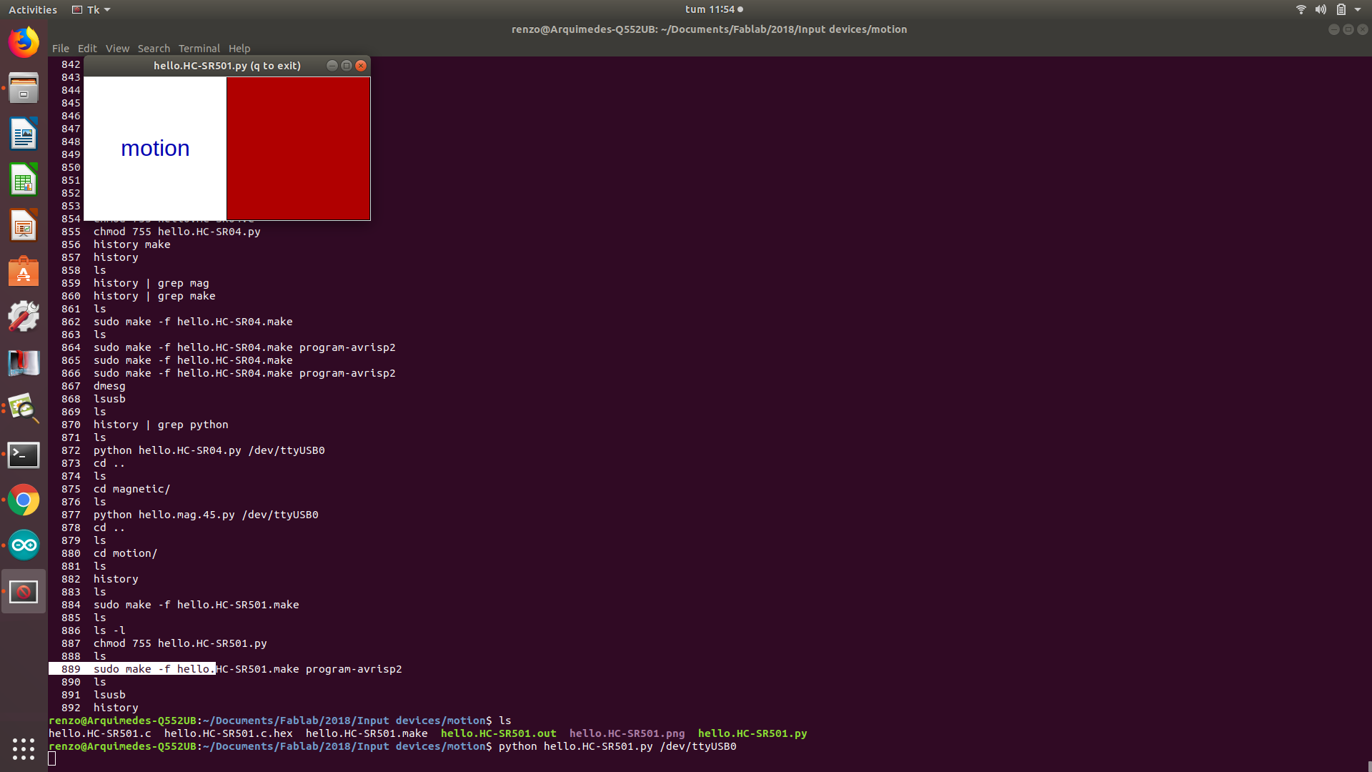
Motion
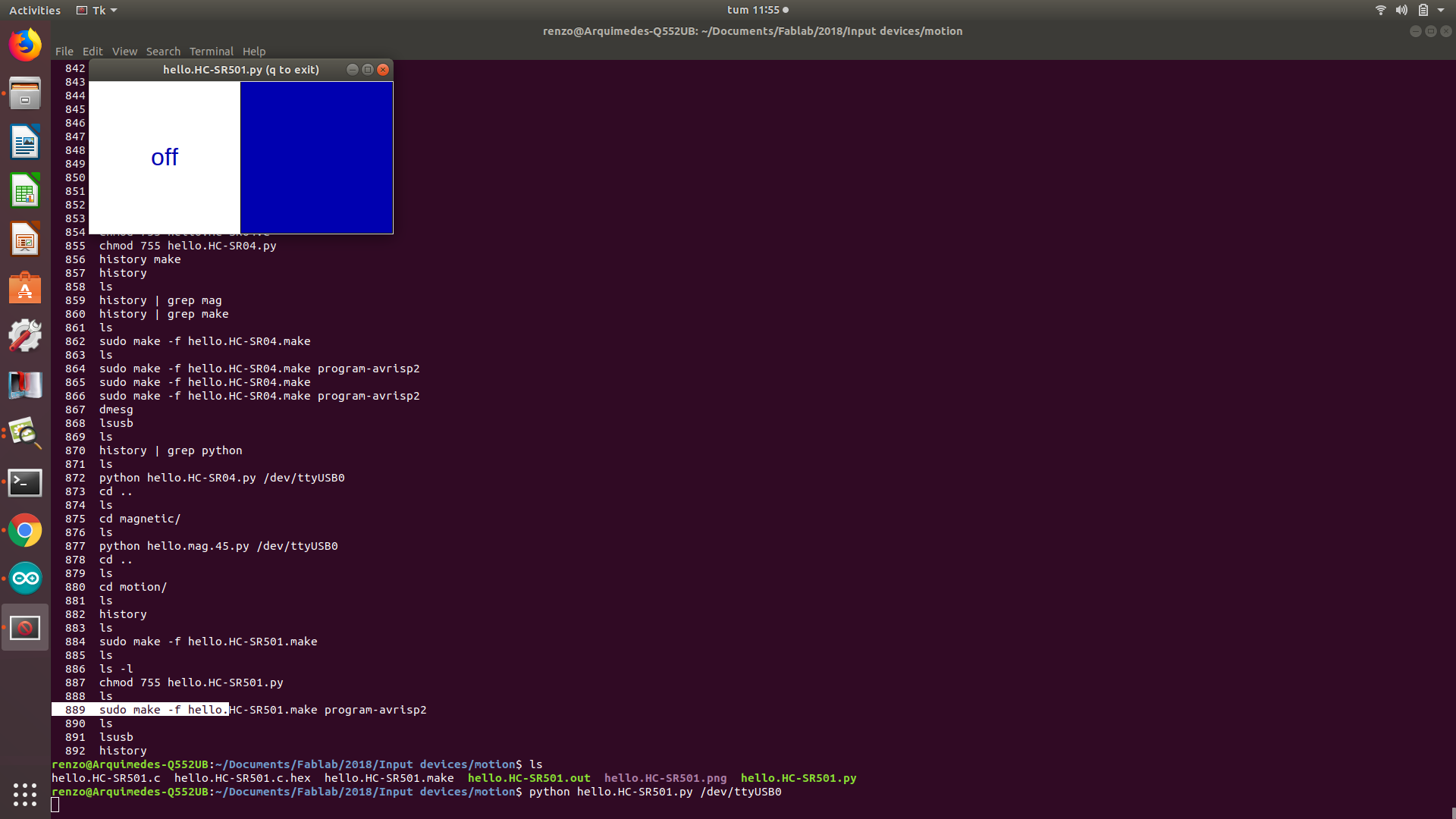
This motion sensor can be set the delay for its activation. You may read all the information about it at HC-SR501
I used the same script given Fabacademy, however if you are using arduino you may use the following script.

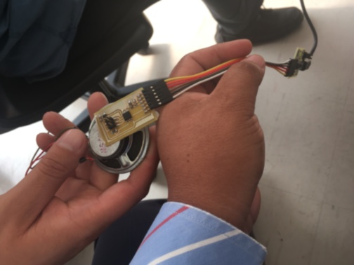
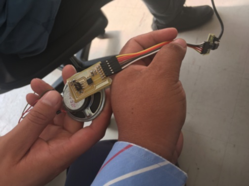
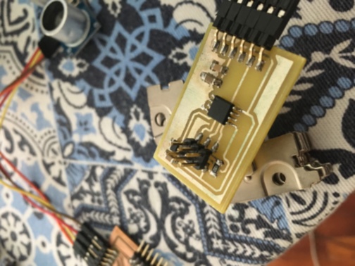
Halleffect
The Allegro halleffect sensor can be used at variety of applications like: Displacement, angular position, and current measurement. You may download the design files here. The code files are the same at the input devices Fabacademy classes.
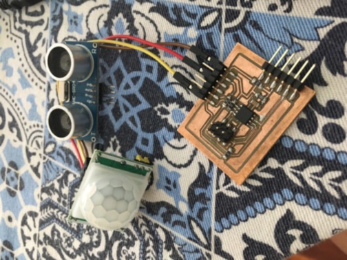
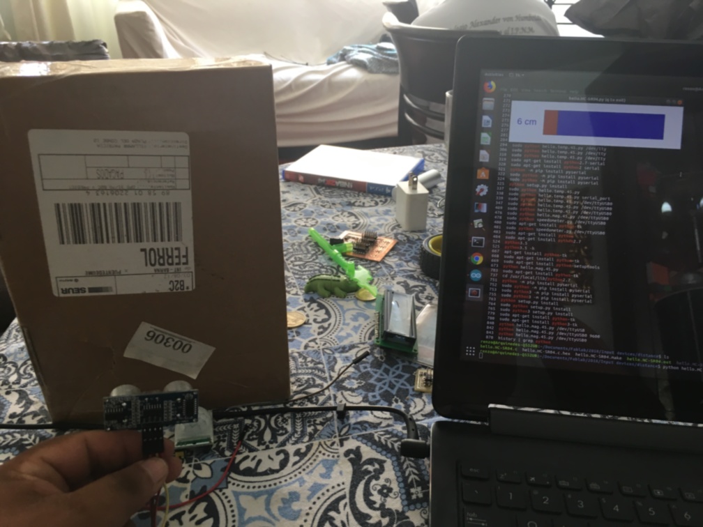
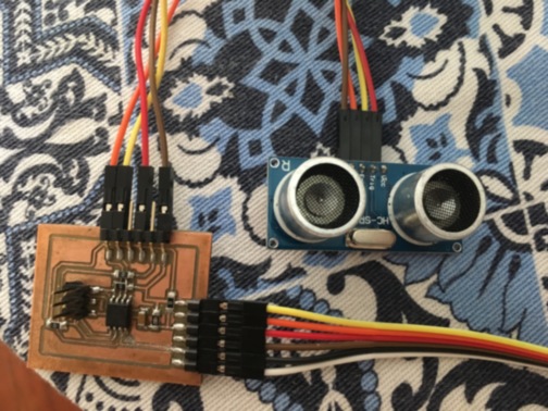
Distance
The HC-SR04 ultrasonic sensor help us to measure the distance between the emitter (ultrasonic sensor) and a object. You can measure an object up to 4 meters of distance.
The sensor works with the following considerations:
- Using IO trigger for at least 10us high level signal.
- The Module automatically sends eight 40 kHz and detect whether there is a pulse signal back.
- IF the signal back, through high level , time of high output IO duration is the time from sending ultrasonic to returning.
Test distance = (high level time × velocity of sound (340 m/s) / 2
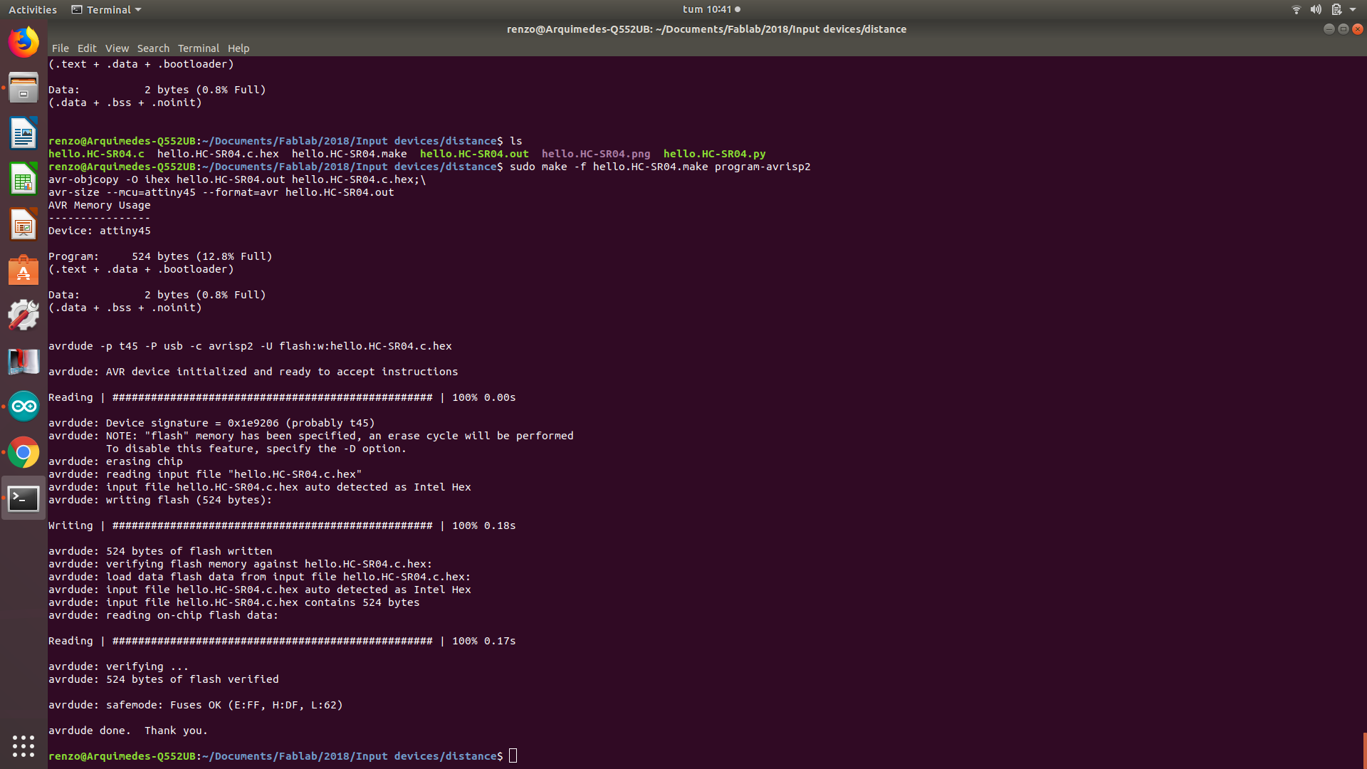
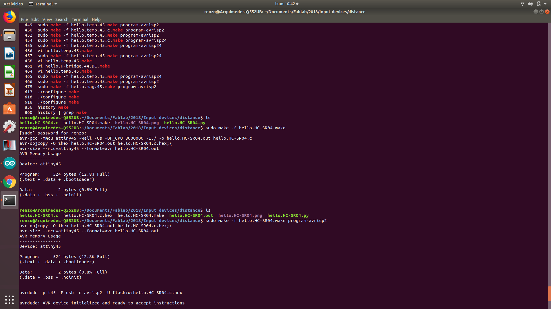
I used the Fabacademy code, just modifying the ports and the microcontroller at the makefile. However you may use this code too. Just consider the right ports.
Group assignment:
Probe an input device’s analog levels and digital signals Please take a look at Group assignment of Silvia Lugo web page.