12. Output devices
Individual assignment:
Add an output device to a microcontroller board you’ve designed, and program it to do something.
These week I use the previous generic boards made at the last week Attiny44 board and Attiny45 board.
DC motor driver A4953
I had made a board with a driver A4953. It works with a PWM (pulse width modulation). It is a powerful technique for controlling analog circuits with a microprocessor’s digital outputs. PWM is employed in a wide variety of applications, ranging from measurement and communications to power control and conversion
The A4953 driver contains an internal Hbridge, so the direction of the motor can be control.
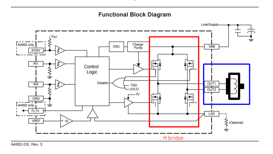
You may download the design files here. I tried it with three types of DC motors. So far so good it works pretty well.
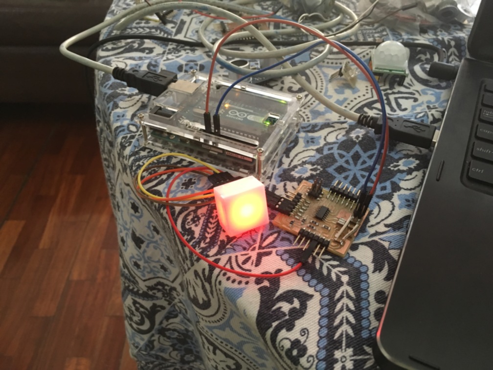
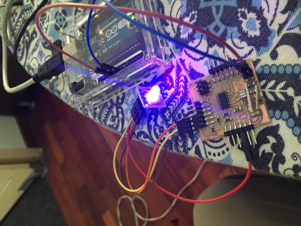
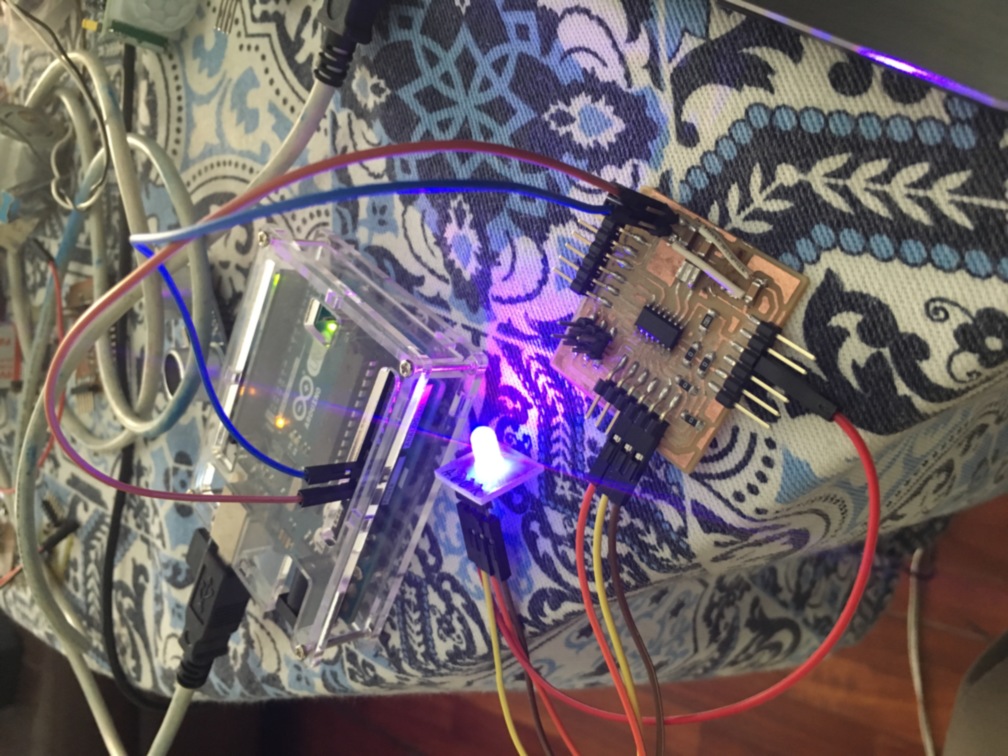
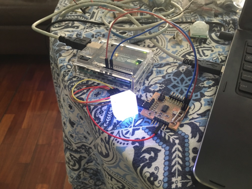
RGB Led
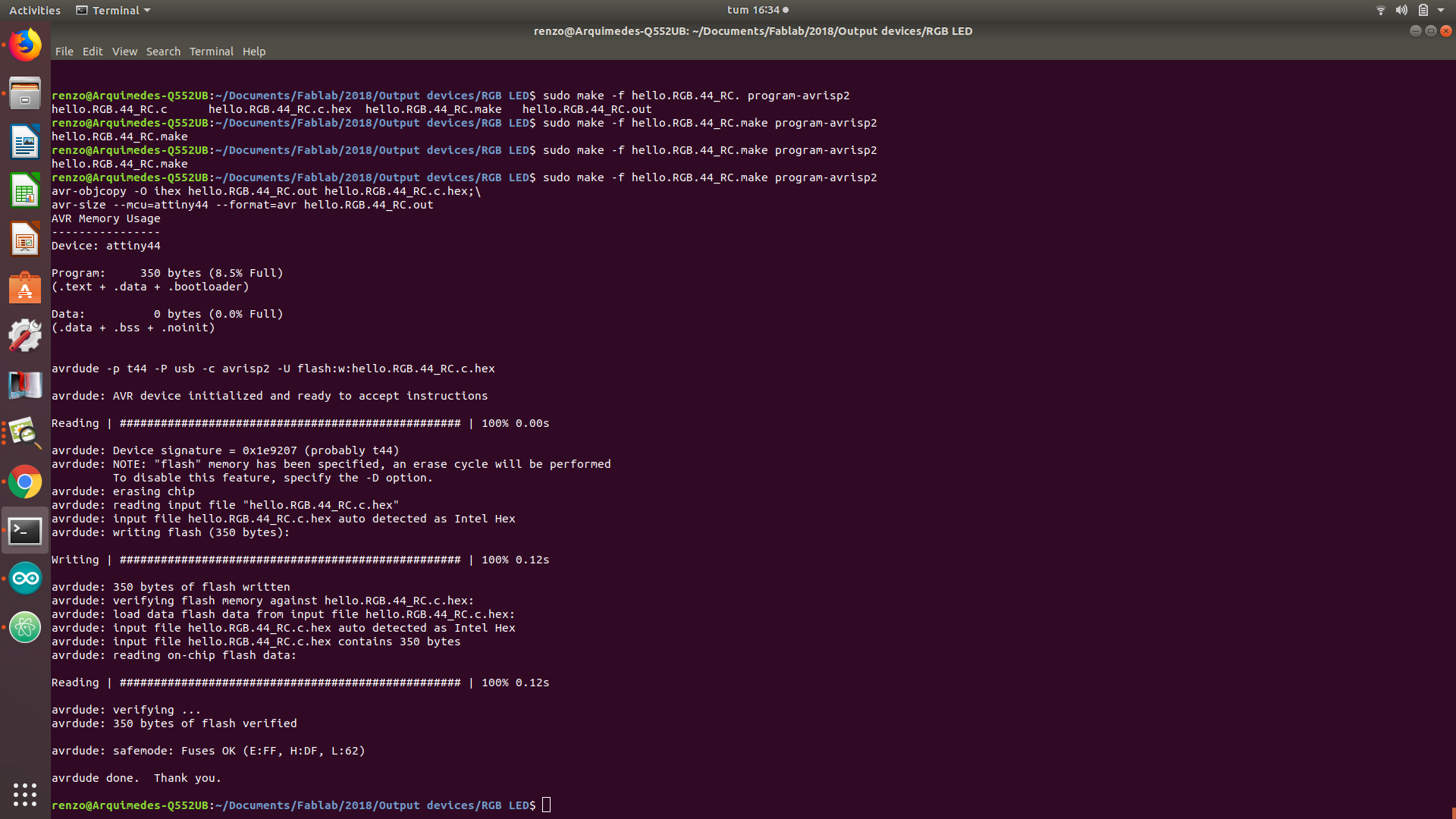
I used the generic Attiny44 board. In order to make a more fancy project. The RGB led was covered with an acrylic box. You may have the designs of the RGB led here.
The program is also available.
I think the PWM is really useful. I will check deeply how it works. So in future better designs can be executed.
Group assignment:
Measure the power consumption of an output device. Please take a look at the Group assignment of Silvia Lugo web page.