20. Project development
This was the final week of fab academy 2019.In this week i have to make the final project and more about the time manangement.Due to the time and economic status I fixed my plan to go with my second estimated idea for making an Air mouse.
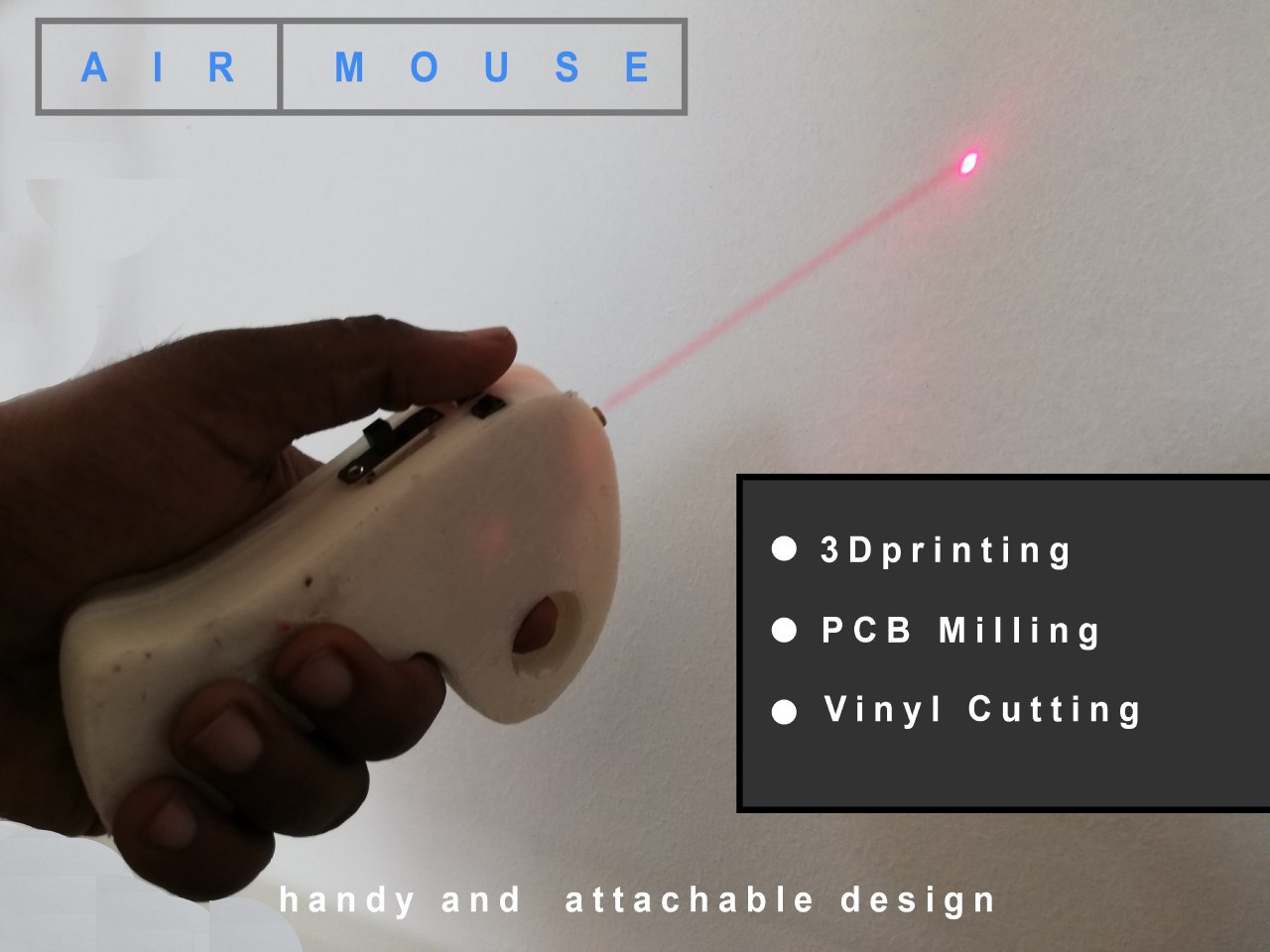
AIM
My aim was to make a handy and body attachable Air mouse that can be controlled without touching any surface with the added feature of pointer that can be used while presentations etc..
TIME
As on 07/06/2019, I have 10 days to complete my project work. My presentation is on 17/06/2019.
PROCUREMENT
Completed about 90 percent of the procurement for the Project from outside and the rest of the materials were used from the lab itself.
Items that are to be purchased from outside the lab
-
Mpu 6050
-
HC05
-
Jumber wires.
-
LI-PO Battery
-
FT4060 Charging module
SCHEDULING
Total 10 days has left with me .SO I planned 4 days for thr pro gmming and pcb designing and milling.The 2 days for completeng other electronics hardware and fusion of sensors.the designing was estimated to do in two days and 3d printing it in 1 day and its iteration.the remining time for final documentation.
Before starting it was clear that things I can’t have a detailed and elaborate plan with such vagueness in everything. And process like designing electronics design, programming and testing can take hours or days. I could not fix clear schedule for these processes. All I have decided that I would work in spiral development pattern. I would start with all process, all of which can be started parallely. The advantage with this approach was that I won’t lose the nerve in worst scenarios.
Electronics design and PCB fabrication - 7/06/2019 to 9/06/2019 (3 days) Programming and testing - 10/06/2019 to 13/06/2019 (4 days) Designing and fabrication - 14/06/2019 to 15/06/2019 (2 days) Assembly and extra slack - 15/06/2019 (1 day) Video and slide preparation - 16/06/2019 (1 day)
What material shall I use
Milling was done as usual by using copper cladding and the micoconrollers as ATMEGA 328 p or ATMEGA 32u4(HID) The 3D printing was estimated to do with ABS.
COMPONENTS USED
1.Copper board
2.Atmega 328 p
3.MPU 6050
4.HC05 Bluetooth
5.Resistors of 10k(4 nos)
6.Resistors of 1 k(2nos)
7.0 ohm resistors (3nos)
8.Resonator of 20 mgz
9.Capacitor of 1uf
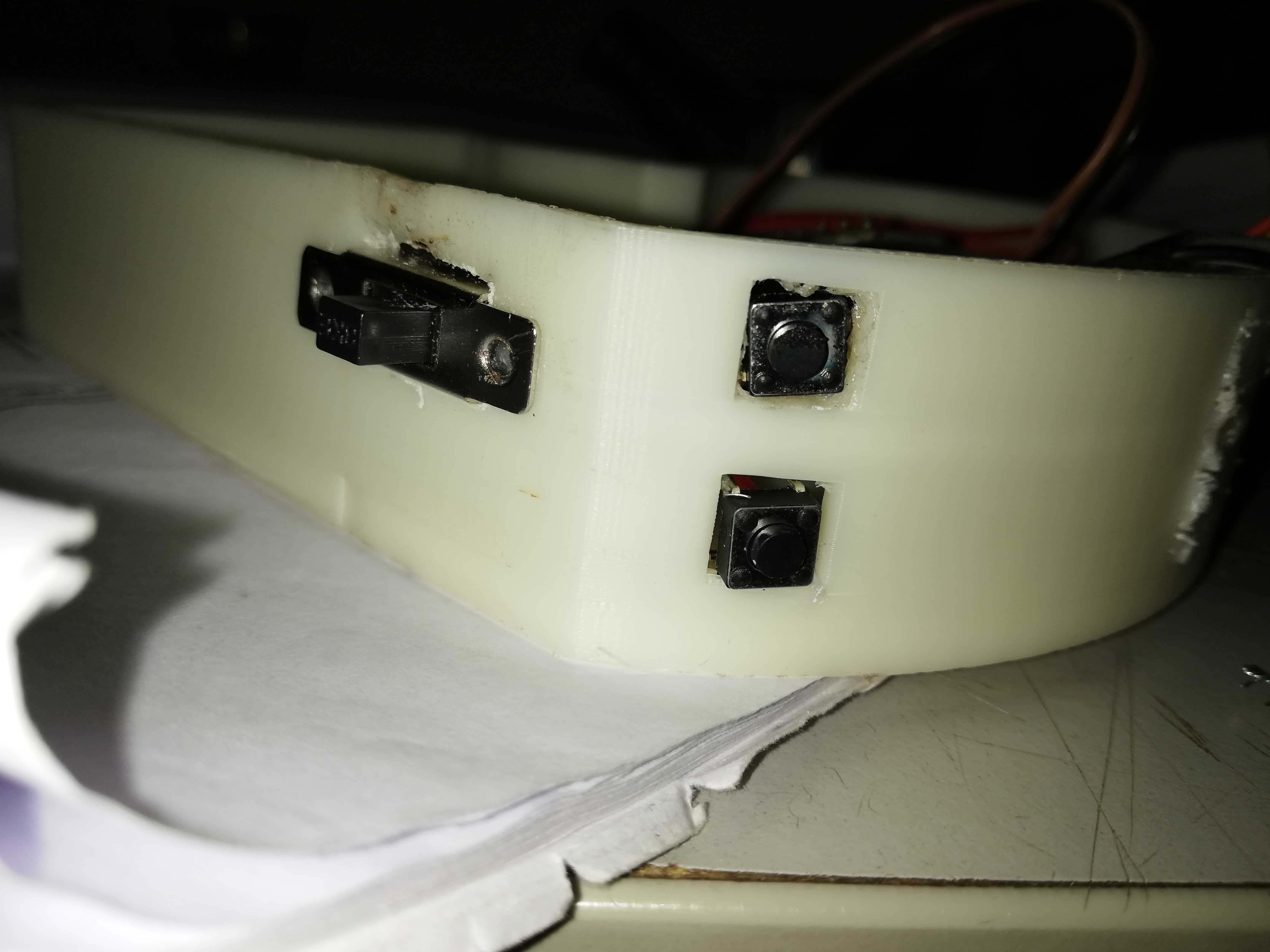
10.Slide swithc (2nos)
11.Push Button (2 nos)
12.Jumper wires
13.Avirsp pin header(2*3)
14.FTDI pin header (1*6)
15.LIPO battery
16.FT4060 Charging module
Then Identified the process or machines that can be used for execution of the project.
FABRICATION’S DONE
Basically the mouse contains 5 parts
1.Electronics designing
2.Electronics production
3.Programming
4.Networking
5.3d Designing
6.3d Printing.
After estimating the components I checked component availability and the other components were bought from nearby shops
BILL OF MATERIALS
1.Copper board FROM FAB LAB
2.Atmega 328 - “”
3.MPU 6050 180 INR(3 dollars approximately)
4.HC05 Bluetooth 300 INR(5 Dollars approximately)
5.Resistors of 10k(4 nos) FROM FAB LAB
6.Resistors of 1 k(2nos) “”
7.0 ohm resistors (3nos) “”
8.Resonator of 20 mhz “”
9.Capacitor of 1uf “”
10.Slide switch (2nos) 35INR(0.5 dollars)
11.Push Button (2 nos) FROM FAB LAB
12.Jumper wires 70INR(1 DOllar)
13.Avirsp pin header(2*3) FROM FAB LAB
14.FTDI pin header (1*6) “”
15.LIPO battery 600INR(9 Dollars approximately)
16.FT4060 Charging module 140INR(1.5 Dollar)
Then I started to do the project.g
Through the making
1.Electronics designing
With the knowledge gained from the assignments I worked on AUTODESK EAGLE for the purpose of board designing.
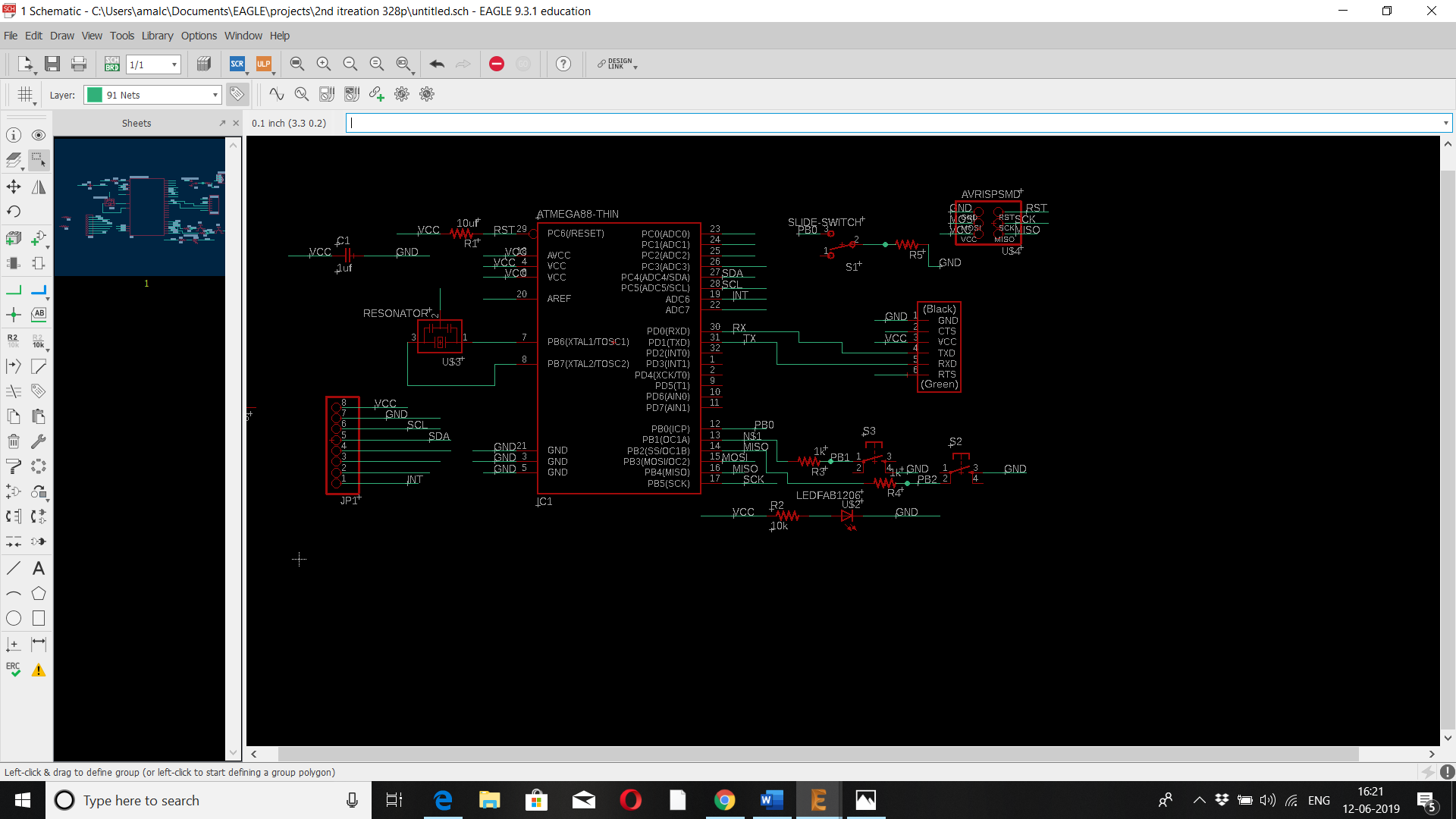 My basic idea was to make two boards .The first board will sense the x,y motion using mpu 6050 ,process by using atmega 328p and then transmit the signal through HC05 module to a HID enabled board.
My plan was to make a Human Interface device with 32u4
 So while I was working with 32u4 mcu , the milling was a failure because the traces left unmilled and it is understood that the existing library doesn’t meets 16 mil.
 So I planned to edit the traces in Adobe Photoshop and milled .But this time the traces were much thin and too hard for soldering.
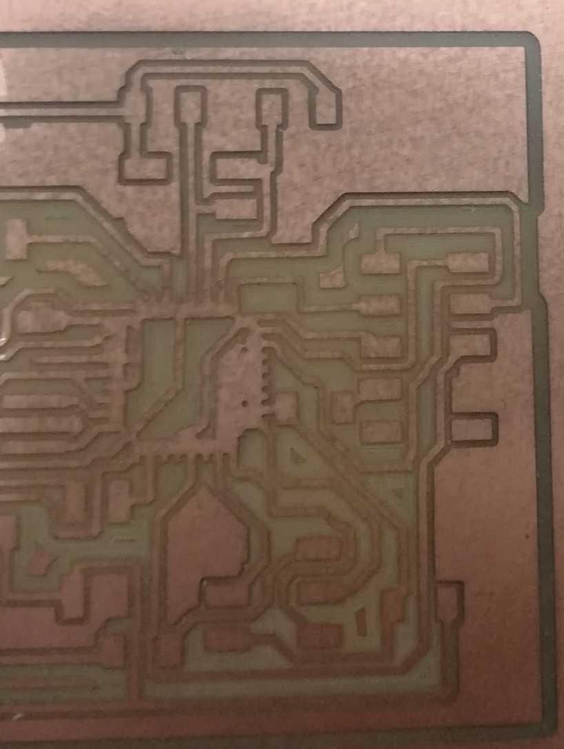
2.Electronics production
Even though I designed a board using atmega328 enabling a serial output by hc05 to transit the serial data and to sense the XY directions using 6050mp which comprises about gyro and accelerometer.
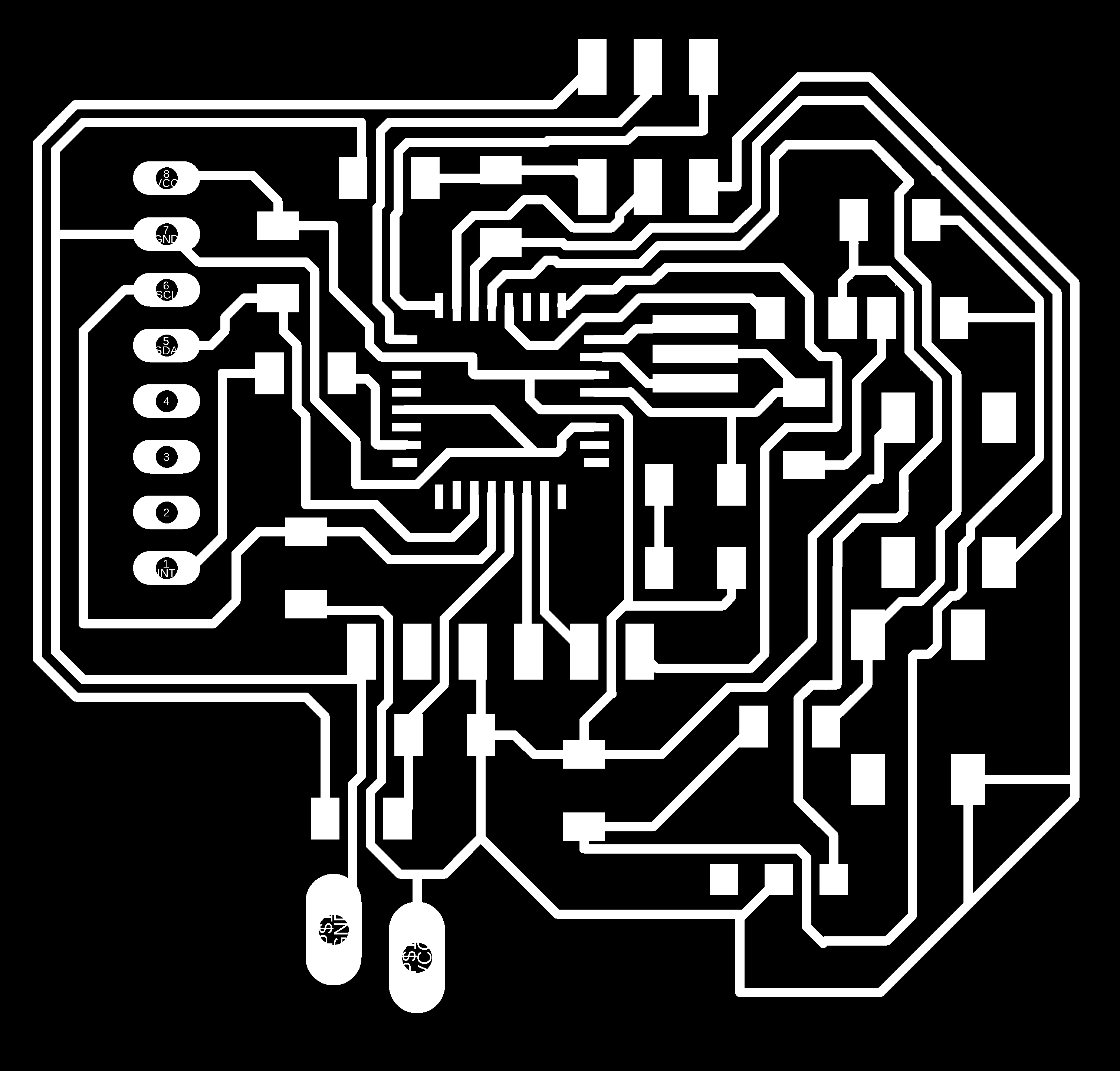
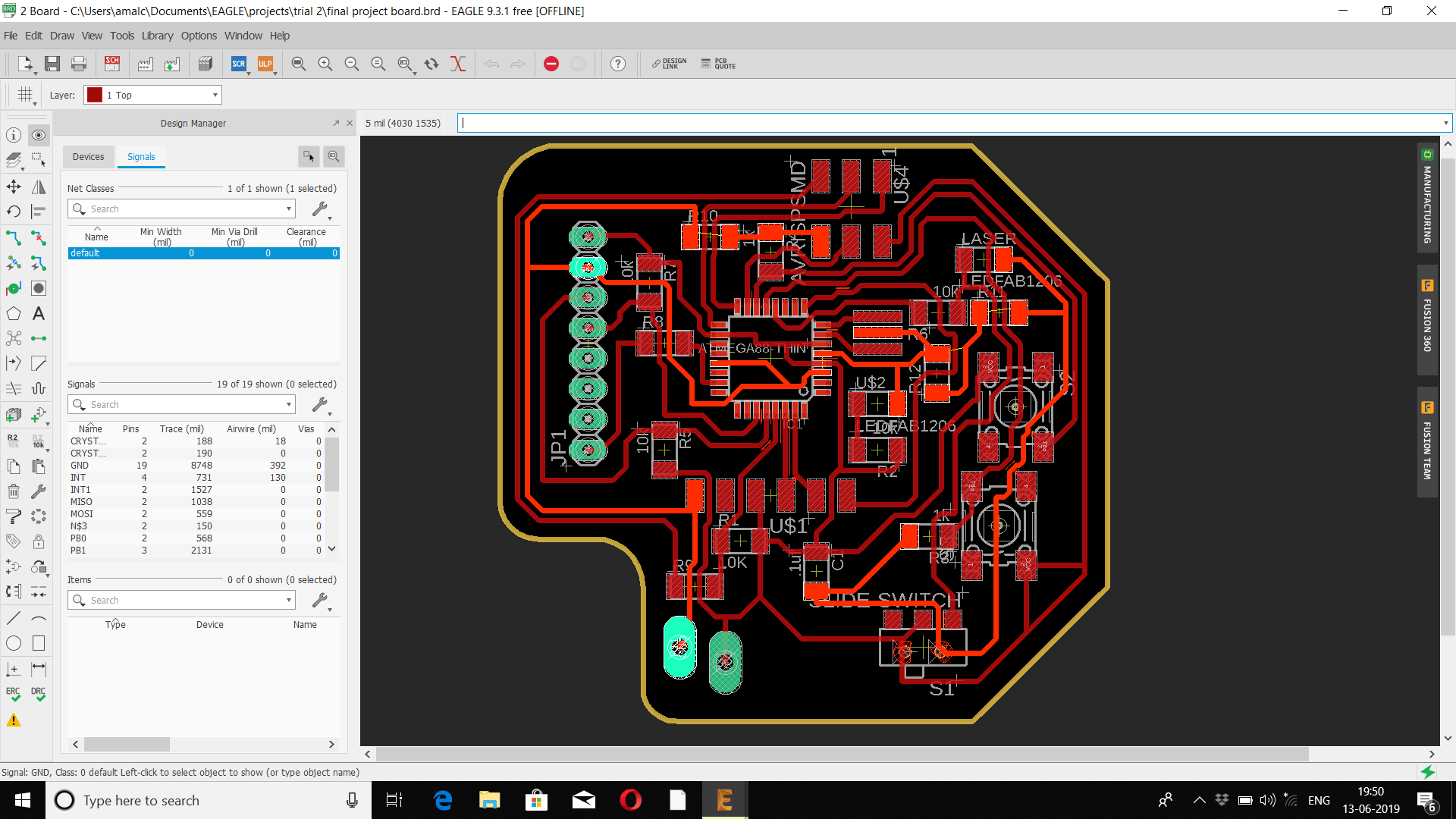
The First design was too large to make it wearable design and made it as a first iteration of board.
So I redesigned to make it compact and achieved it to my best.
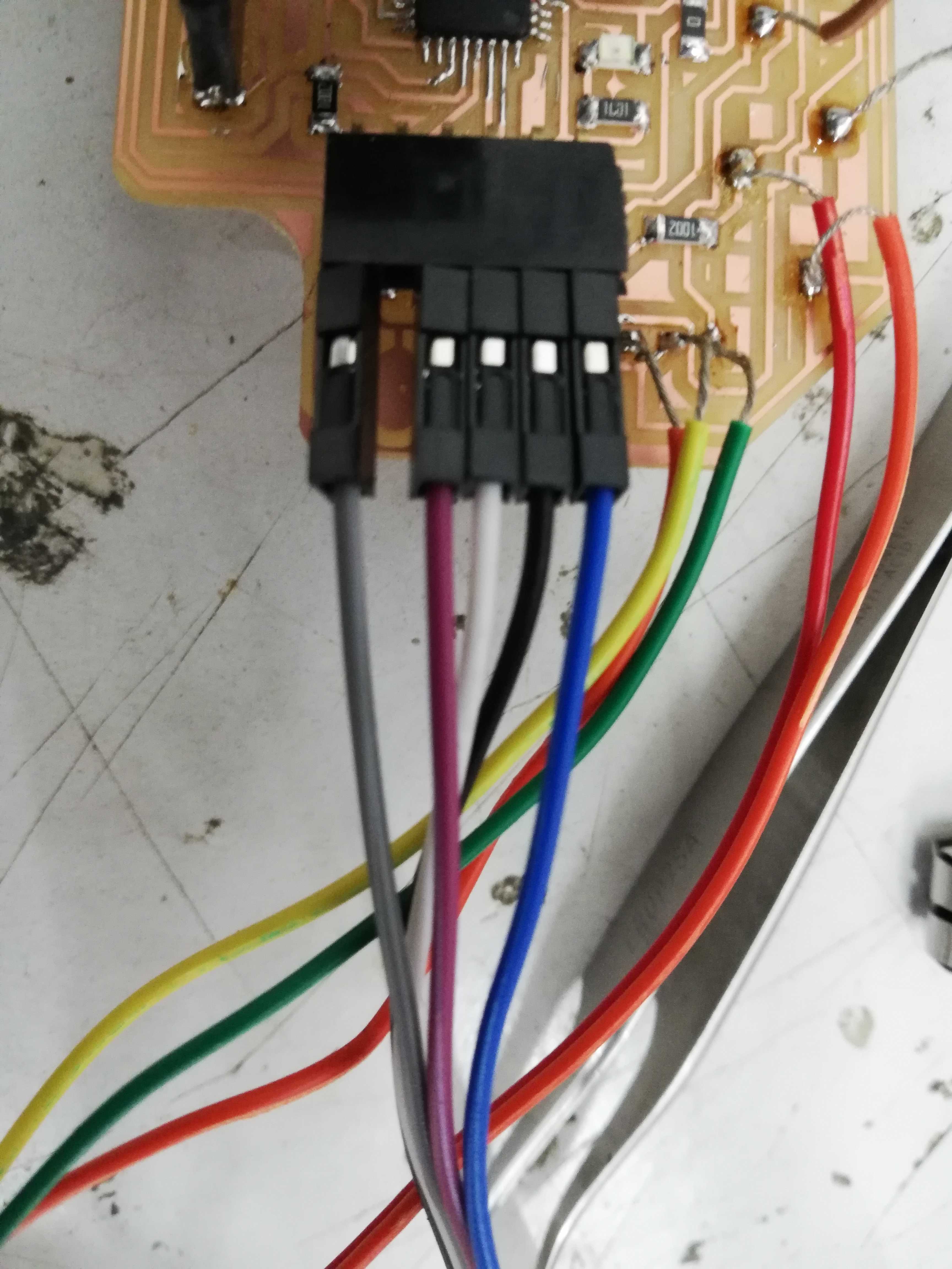
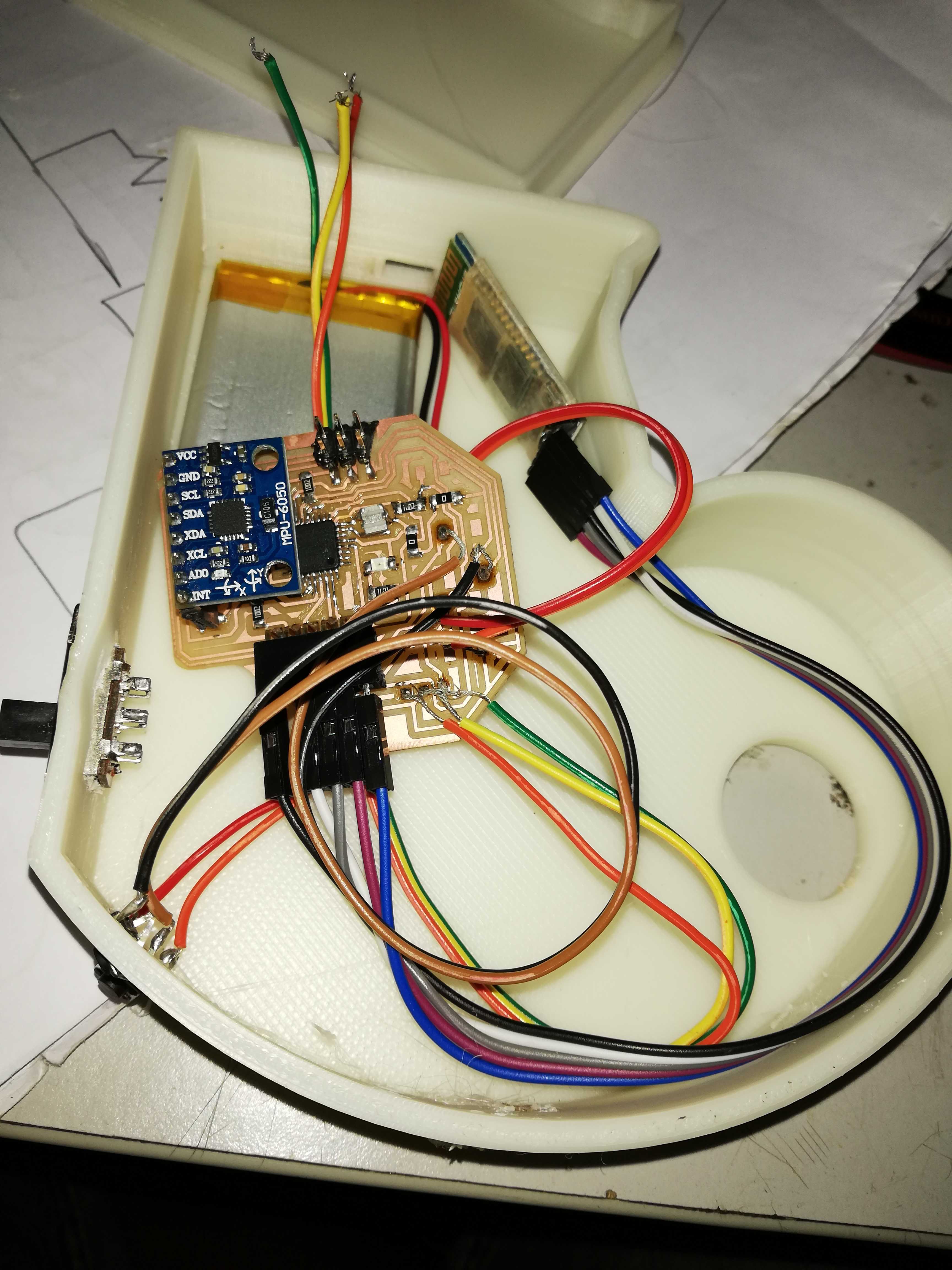
After that I soldered the board and all the modules were connected accordingly.
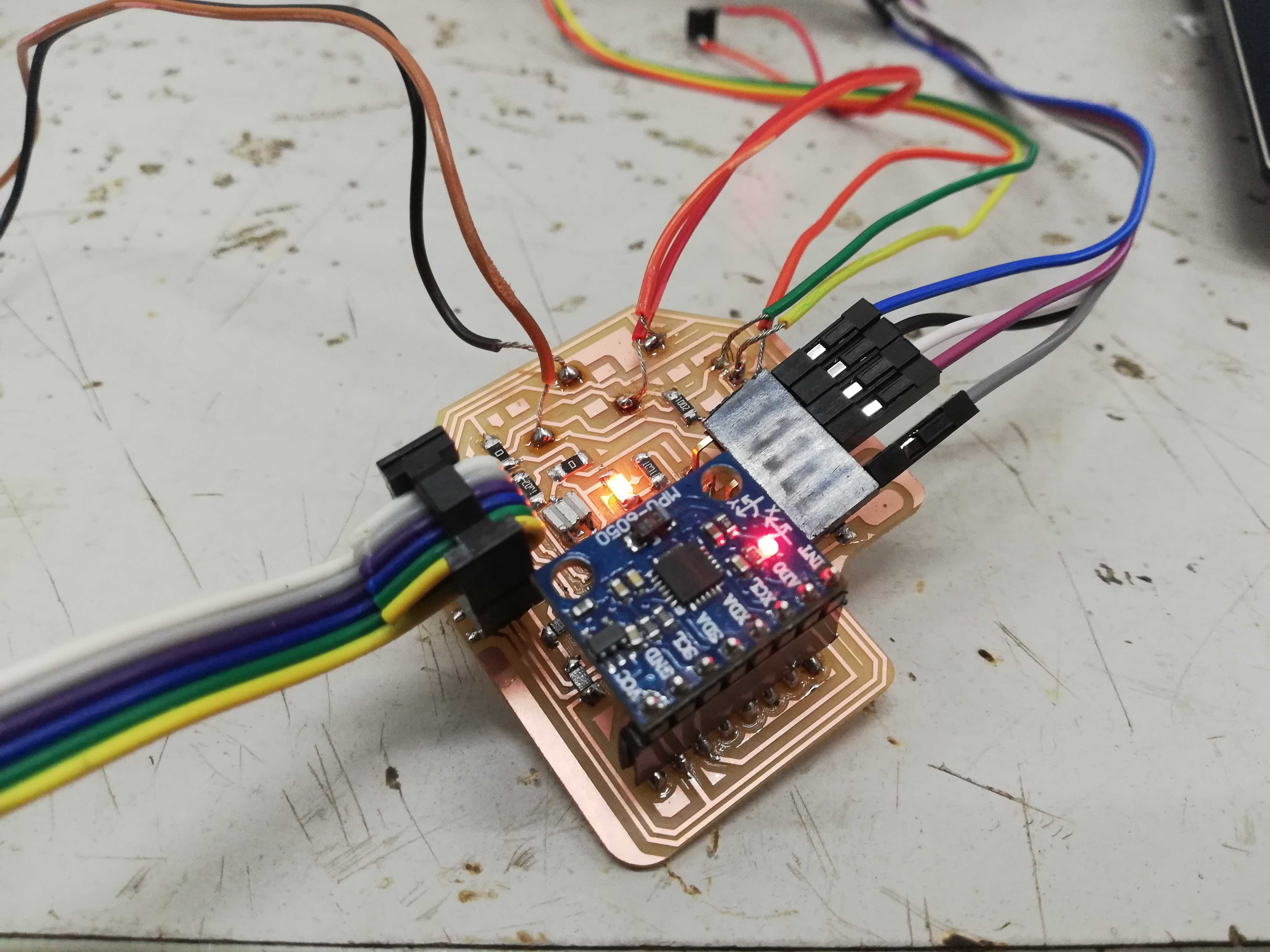 Since I want to make it a portable design I provide the external source as LIPO battery
3.Programming
After burning the bootloader I added then necessary library that is needed for running the program and the program was executed.
* Code to control the mouse pointer
* Change values at vx and vy (+300 and -100 in my case)
* using the TEST code to make your project work.
"code"
#include <Wire.h>
#include "I2Cdev.h"
#include <MPU6050.h>
#if I2CDEV_IMPLEMENTATION == I2CDEV_ARDUINO_WIRE
#include "Wire.h"
#endif
MPU6050 mpu;
int16_t ax, ay, az, gx, gy, gz;
int vx, vy;
#define OUTPUT_READABLE_ACCELGYRO
const int leftButton = 9;//enabling left button
const int rightButton =10;//enabling right button
const int mode = 8;
const int laser =A0;//enabling laser button and making the muc on hold condition while enabling the laser
int state;
void setup() {

if I2CDEV_IMPLEMENTATION == I2CDEV_ARDUINO_WIRE
Wire.begin();
#elif I2CDEV_IMPLEMENTATION == I2CDEV_BUILTIN_FASTWIRE
Fastwire::setup(400, true);
endif

pinMode(leftButton,INPUT);
pinMode(rightButton,INPUT);
pinMode(mode,INPUT);


Serial.begin(9600);

mpu.initialize();

}
void loop() {
  mpu.getMotion6(&ax, &ay, &az, &gx, &gy, &gz);

  vx = (gx+300)/200; // "+300" because the x axis of gyroscope give values about -350 while it's not moving. Change this value if you get something different using the TEST code, chacking if there are values far from zero.
  vy = -(gz-100)/200; // same here about "-100"

  // digitalWrite(laser,LOW);
  Serial.println(vx);
  Serial.println(vy);
  delay(30);

  digitalWrite(laser,HIGH);

 delay(20);
 }
4.Networking
After burning the program to using AVRISP using usbtiny i tested the serial output using bluetooth terminal in mobile phone and it was working.
Then I tried to connect between HC05 using binding technique because it was unable to send two data at a time ie.data from x direction and the y direction and it did not worked.
After consulting with the instructor he advised me to write a python script which enables the mouse function and wrote the script to import serial data and my instructor helped me.
import serial.tools.list_ports

# import win32api
# import time
# import math
# import mouse
from pynput.mouse import Button, Controller


comlist = serial.tools.list_ports.comports()
connected = []
com_stmt = "List of COM ports: " if comlist else "No COM ports found"
print(com_stmt)
for index, element in enumerate(comlist):
  connected.append(element.device)
   print str(index + 1) + ": " + element.device
Flag = False

  while comlist and not Flag:
   print("Select the COM Port")
   selected_port = input() - 1
   if -1 < selected_port < len(comlist):
     print(connected[selected_port])
     Flag = True
  else:
 print("Wrong COM Port. Try again.")

if Flag:
ser = serial.Serial()
  ser.baudrate = 9600
  ser.port = connected[selected_port]
ser.timeout = 1
print "COM Port open" if ser.is_open else "COM Port closed"

if ser.is_open:
    ser.close()
else:
    ser.open()
# with serial.Serial(connected[selected_port], 9600, timeout=1) as ser:
#     x = ser.read()          # read one byte
#     s = ser.read(10)        # read up to ten bytes (timeout)
# line = ser.readline()
while 1:
    # delay(2);

    coord = ser.read_until(';')
    print coord
    # s = mouse.get_position()
    # print s
    if ',' and ';' in coord:
        # pass
        # win32api.SetCursorPos((coord.split(',')[0], coord.split(',')[1]))
        # mouse.move(coord.split(',')[0], coord.split(',')[1])
        # mouse.move(coord.split(',')[0], coord.split(',')[1], absolute=True, duration=0)

        try:
            mouse = Controller()

            # # Read pointer position
            # print('The current pointer position is {0}'.format(
            #     mouse.position))

            # # Set pointer position
            # mouse.position = (10, 20)
            # print('Now we have moved it to {0}'.format(
            #     mouse.position))

            # Move pointer relative to current position

            x = int(coord.split(',')[0])
            y = int(coord.split(',')[1][:-1])
            # y = y
            x = x/10
            print x
            print y
            # print str() + ', ' + str(y)
            try:
                mouse.move(x,y)
            except Exception as e:
                print e


            # try:
            #     mouse.move(int(coord.split(',')[0]), int(coord.split(',')[1]))
            # except Exception as e:
            #     print e

            # mouse.move(5,-5)

            # Press and release
            # mouse.press(Button.left)
            # mouse.release(Button.left)

            # Double click; this is different from pressing and releasing
            # twice on Mac OSX
            # mouse.click(Button.left, 2)

            # Scroll two steps down
            # mouse.scroll(0, 2)
        except:
            pass
    if 'lp' in coord:
        mouse.press(Button.left)

    if 'lr' in coord:
        mouse.release(Button.left)

    if 'rp' in coord:
        mouse.press(Button.right)

    if 'rr' in coord:
        mouse.release(Button.right)


# for i in range(500):

#x = int(500+math.sin(math.pi*i/100) 500)
#y = int(500+math.cos(i) 100)
#win32api.SetCursorPos((x,y))
#time.sleep(.01)
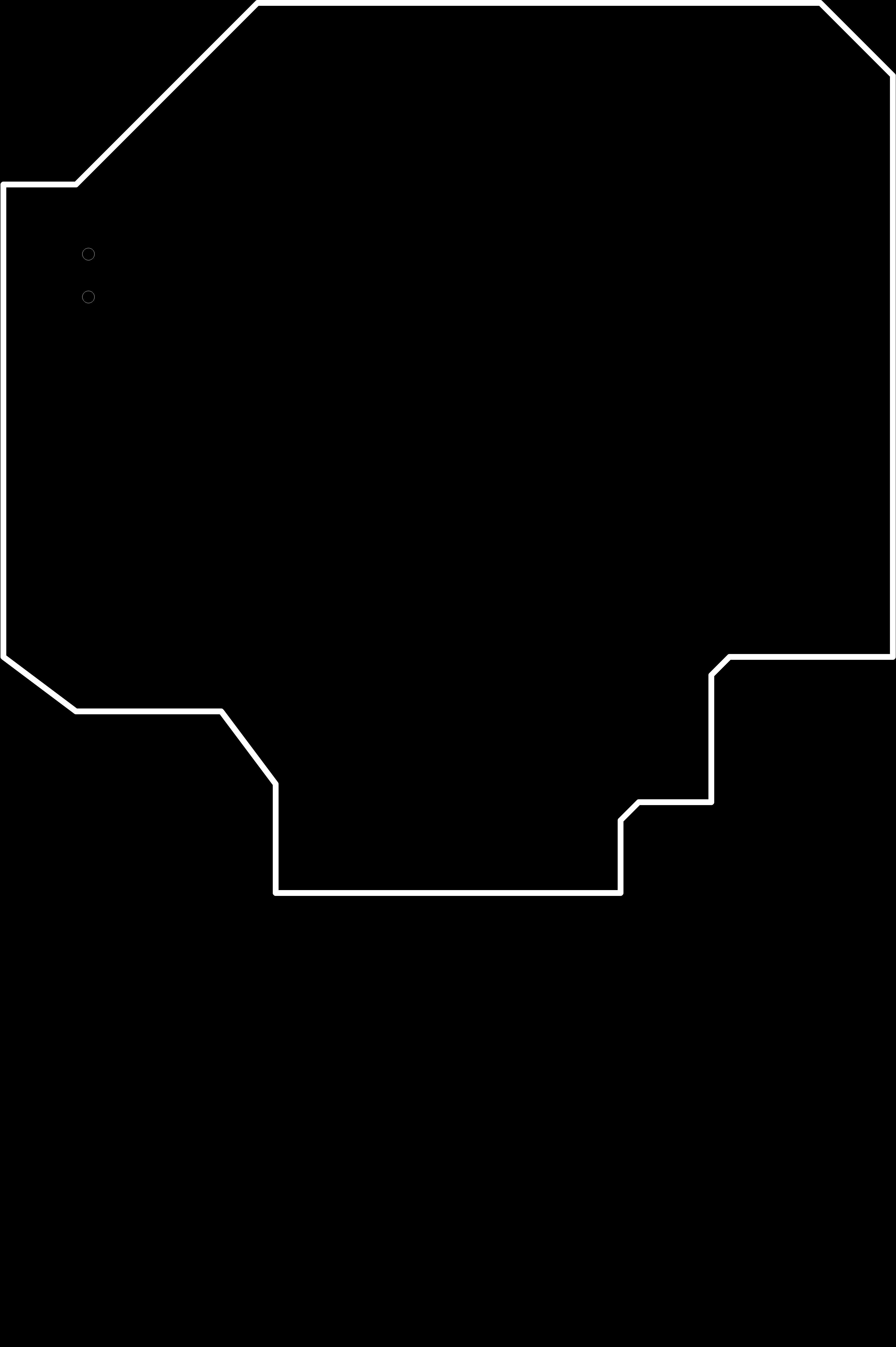
5.3d Designing
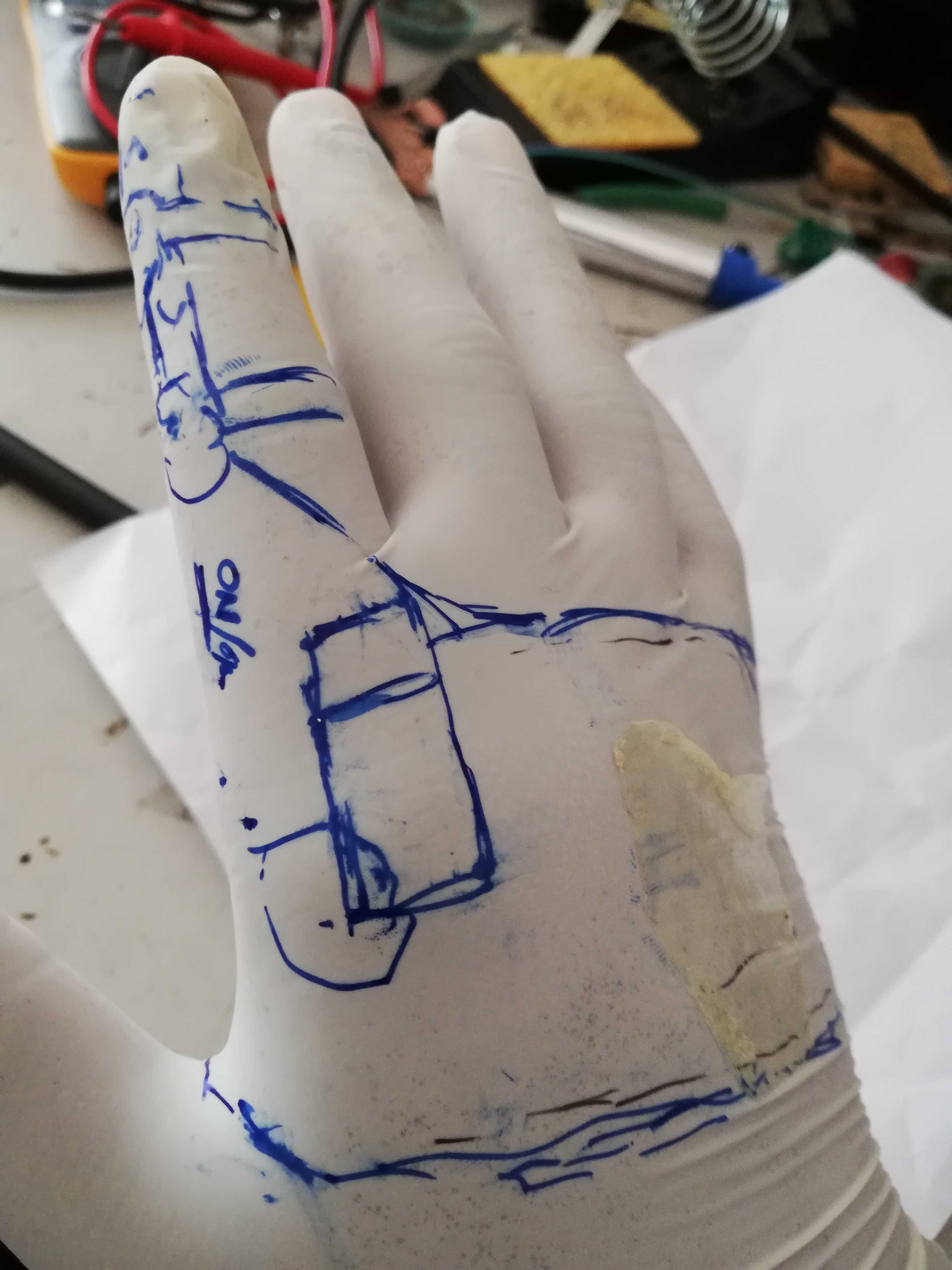
First thing I did was I manually drawn as much possible figures that can be made.
CLICK HERE TO SEE THE DESIGNING VEDIO
Since I was using AUTODESK FUSION 360 for the entire assignments I planned to carry out the same here in the final project too.
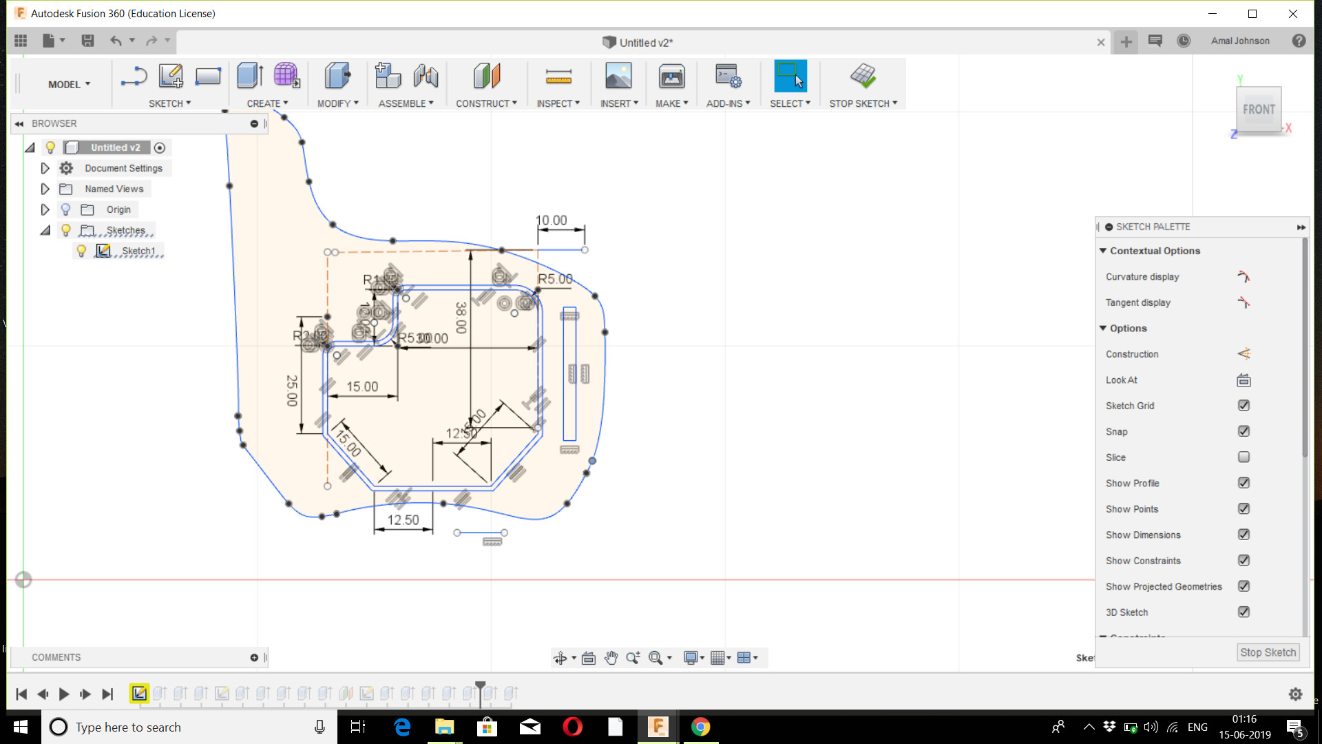
So I designed a 2d designs and extruded and provided the necessary space for fitting all the modules.
But the design was too bulky and I planned to do it again with small space.
So I re-designed and optimized to make it an attachable design to hand.
6.3d Printing.
Then the design file was exported to stl and then moved to k slice software
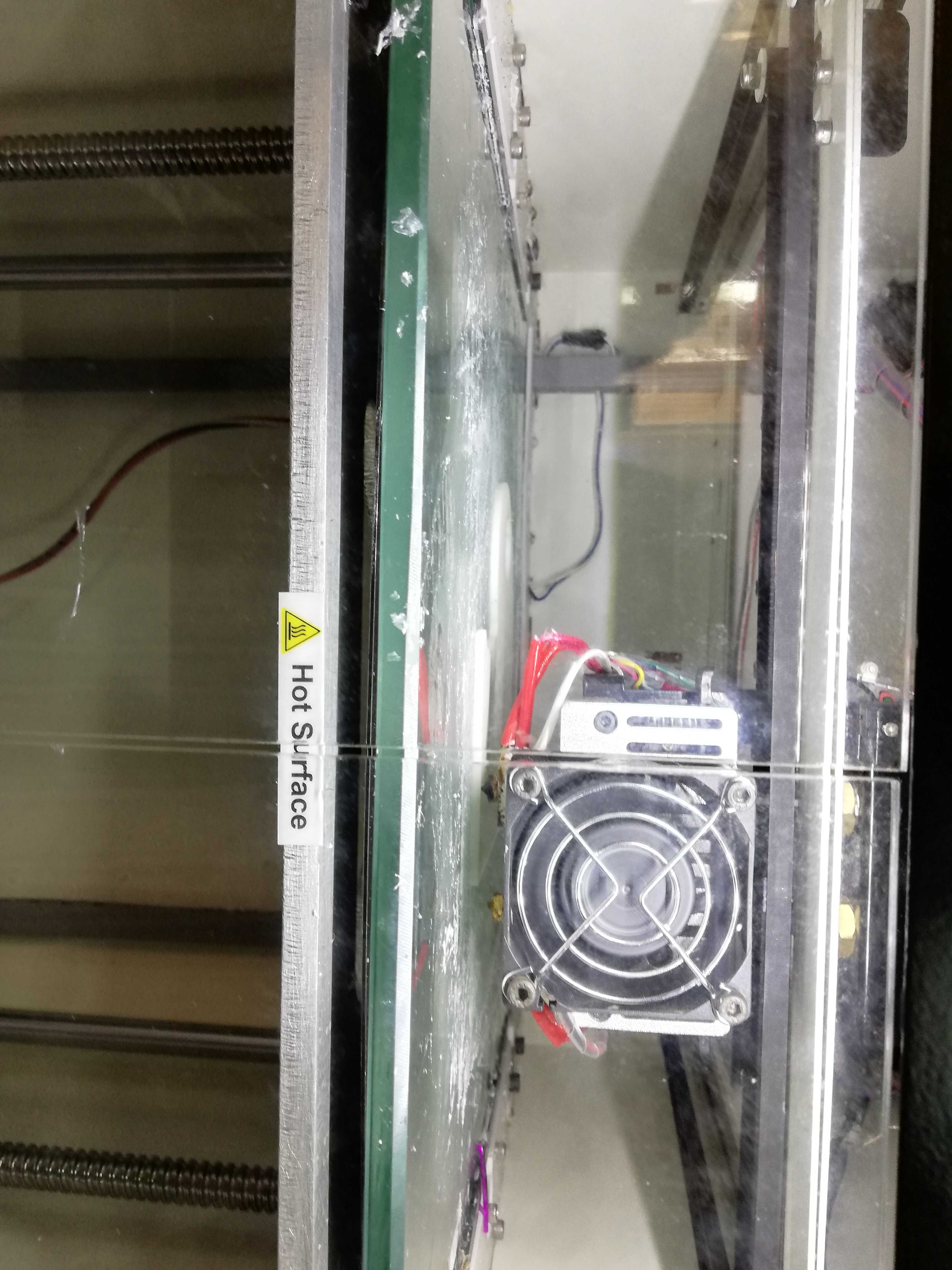
By using K slice software I sliced the design and generated the G-codes
The estimated time was 5 hours for printing
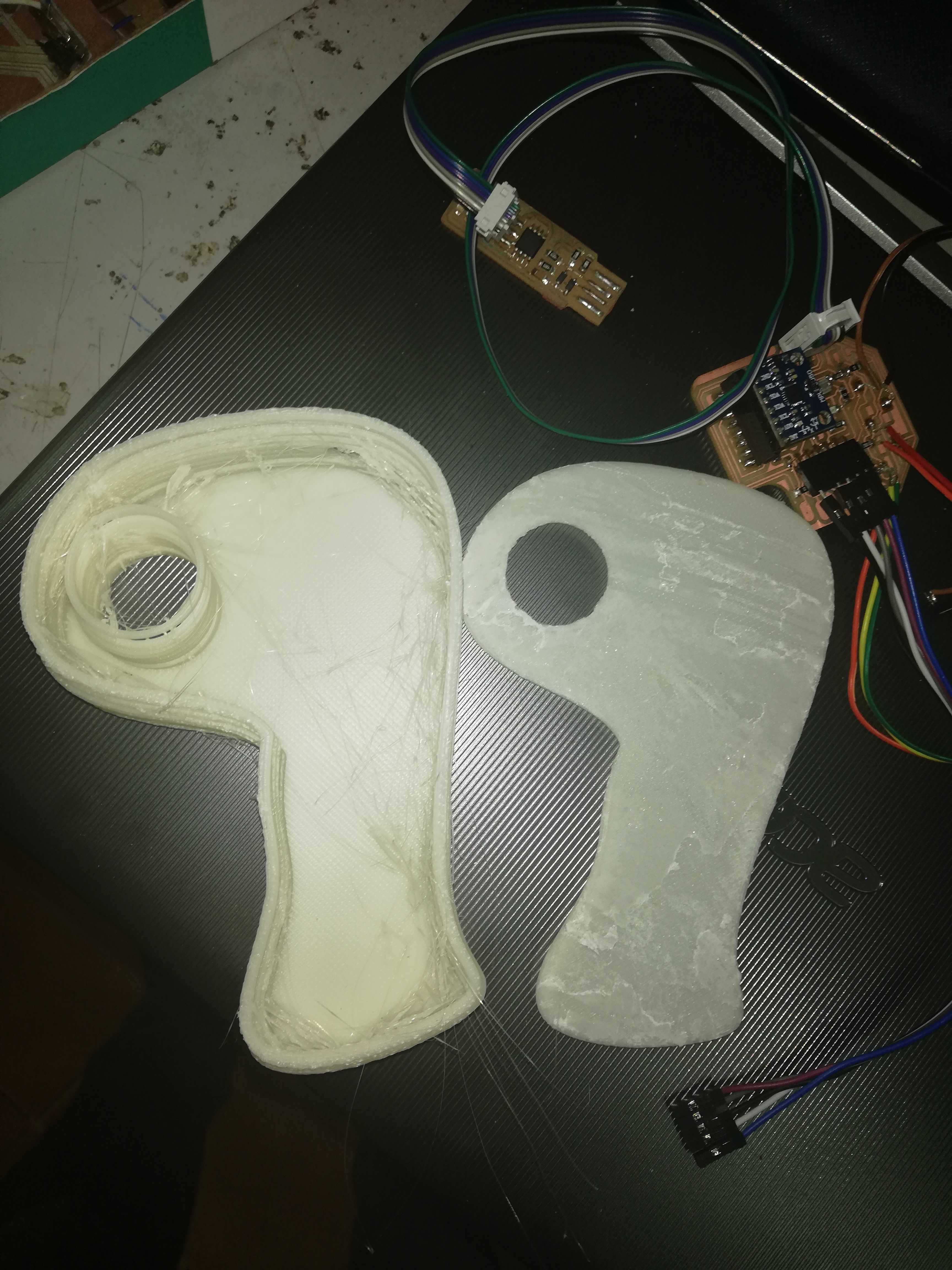
The design was able to print by using divide by zero 3d printer using ABS material.
WORKING
Click here to see the iteration 1
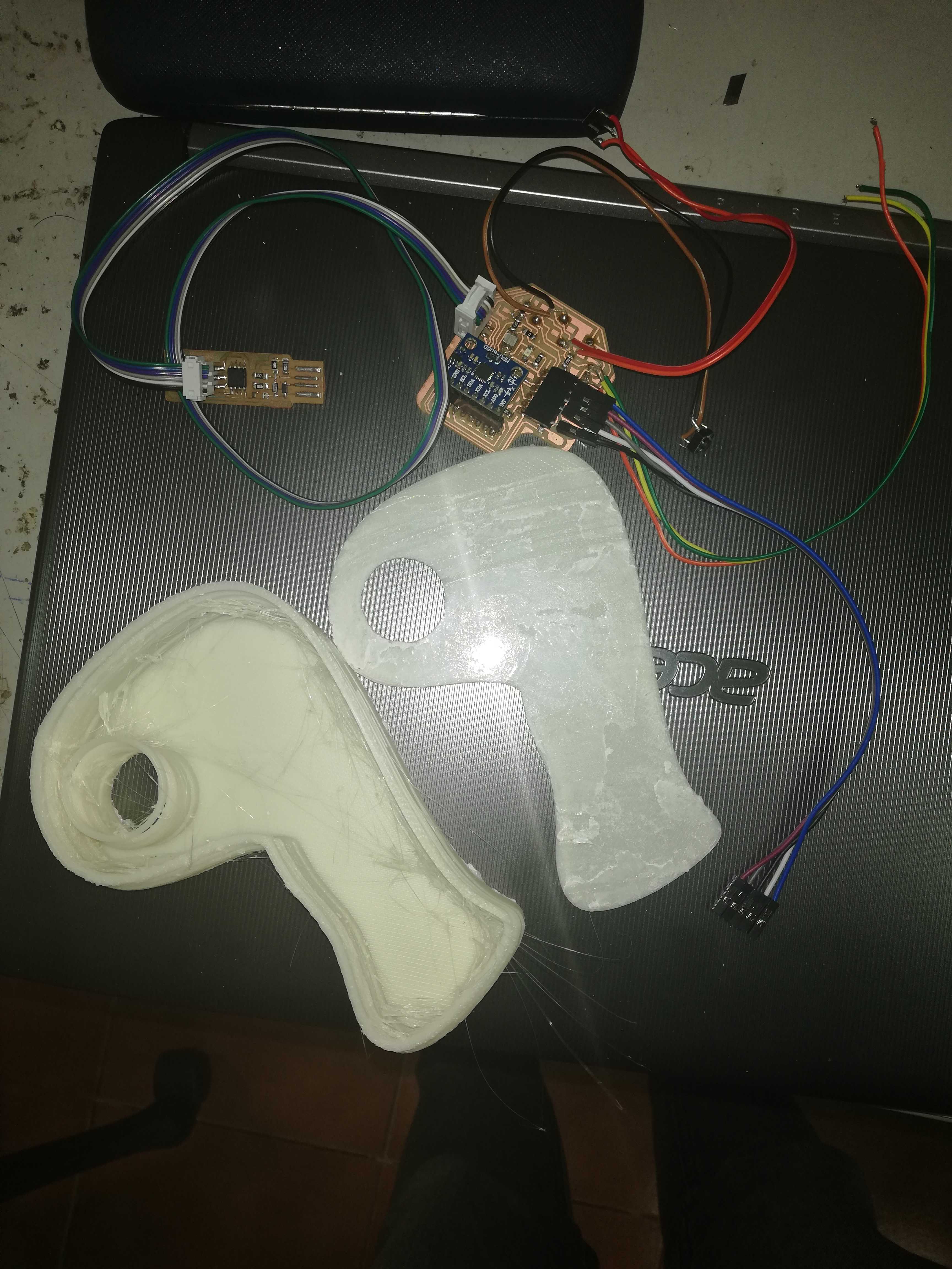
After printing the connections were made and well arranged in the abs printed casing.
Click here to see the iteration 2
After conducting number of iterations the mouse function was optimised and worked.
Click here to see the iteration 3
FILES
click here to open the file
click here to open the file
click here to open the file
click here to open the file
click here to open the file
click here to open the file
click here to view the final project
Presentation poster