8. Computer controlled machining
This week’s aim was to test runout, alignment, speeds, feeds, and toolpaths for the CNC (Computer Numeric Control) machine and make something big.
CNC machine
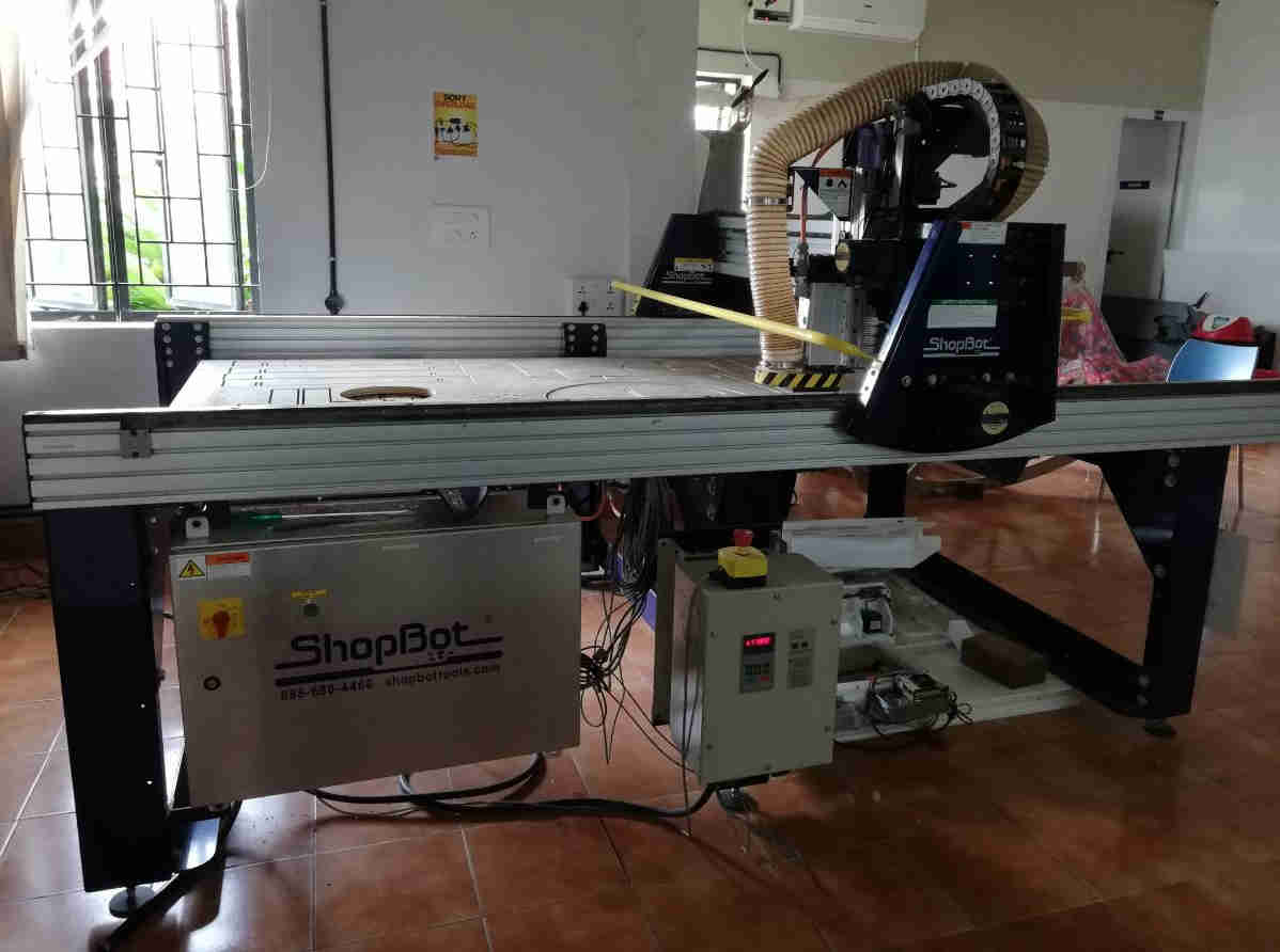
Computer Numeric Control Machine is a machine that automates the machining operations using a predesigned computer model. The 2D/3D drawing is converted to the necessary G code required for the cutting/milling/lathe repeated operations to be performed by the machine to achieve the desired parts. This week we used a 3 axis Shopbot machine to carve out predesigned pieces out of veneer plywood of 18 mm thickness.
 Shopbot
3 axis Shopbot.
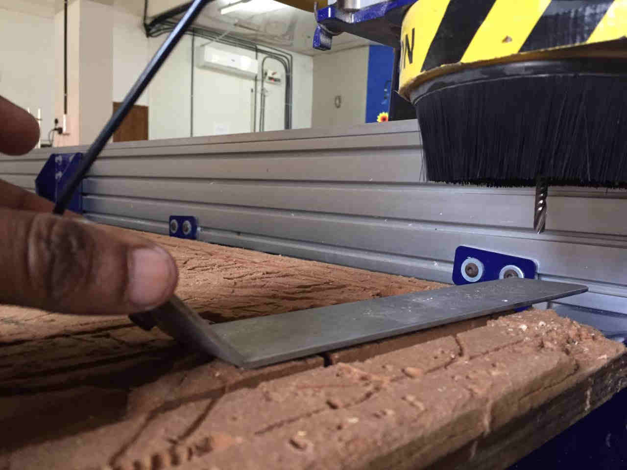
The movable header as you see in the picture runs on parallel girders kept at a distance apart which is specific of the bed size. The header has the rotating spindle with the tool tip, here which is an end mill is capable to moving in 3 directions. The Shopbot can be controlled using a Control Software. The zero coordinates of the machine head is adjusted and calibrated before the start of cutting operation. A zero axis plate is used to zero the Z direction depth of the cutting head. After mounting the drill bit, the plate is touched with the tool tip to calibrate the Z direction zero.
Bed size of the machine here is 8 feet X 4 feet. The bed has a sacrificial layer on top of which we screw down the stock. The machine has a mechanism for collection of dust formed during the operation.
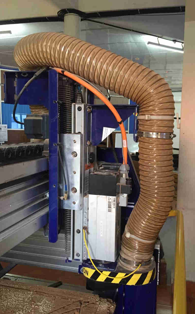 Moving head with vacuum suction tubes
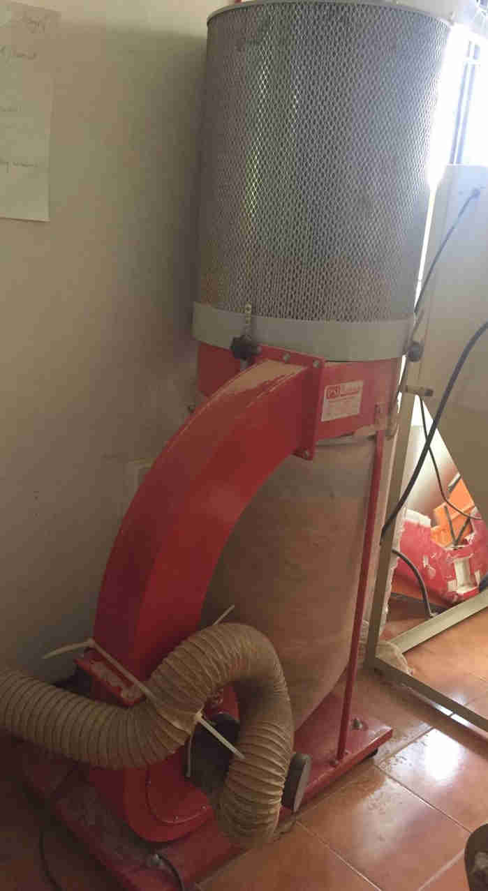 Dust suction apparatus
 The endmill tool is attached to the collet and tightened to the head end.
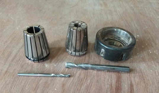
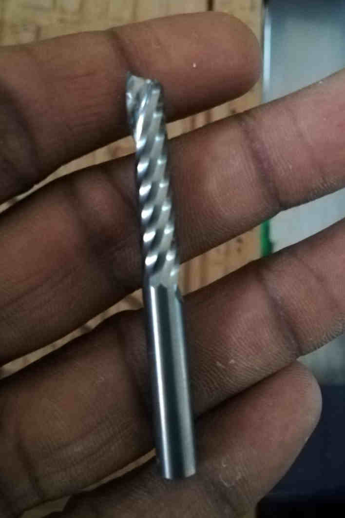
Collets and bits for 3mm and 6mm respectively. Collet nut(extreme right) is used to tighten this
 Zero axis plate used to touch the endmill tip to complete the electric circuit and hence calibrate the zero in Z-direction
Milling Terminology
-
Plunge and Feed:- The motion in X and Y direction is called Feed and along Z direction is called Plunge. These two parameters can be adjusted and is specific to the material type,thickness,type and diameter of the end mill etc.
-
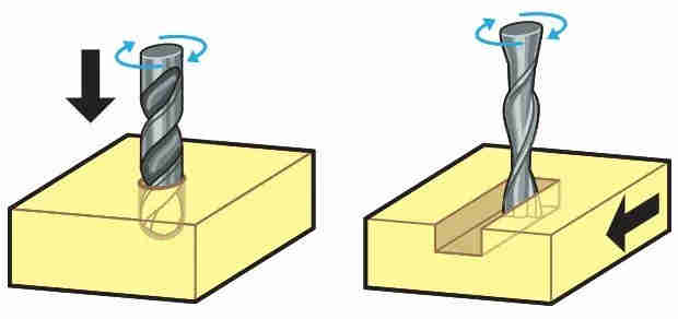
Endmill and Drillbit:- Drill bits are designed to plunge directly into material, cutting axially and creating cylindrical holes. End mills are typically used for horizontal carving and cut laterally. These bits are usually made of High-speed Steel, Solid Carbide, and Carbide-Tipped steel.
 Source:https://makezine.com/2014/09/10/endmills/
 -
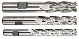
Flutes/teeth of the Endmill:- Flutes are helical grooves running up the cutter between the sharp cutting teeth. It helps in removing the cut material by the teeth by rotation of the cutter during milling operation.Typically, the more teeth a cutter has, the more rapidly it can remove material.
Single Flute - Allows for larger chiploads in softer materials
Double Flute - Allows for better part finish in harder materials
Multiple Flutes - Allows for an even better part finish in harder materials
Source:http://www.industrial-tool-supply.com/morse-cutting/End-mills.html
-
Helix angle of the Endmill:- Angle between the flute and shank axis. The flutes are made helical to allow the slow entry of cutting tool into the material, thereby reducing impact in the cutting tool.
-
Chipload of the Endmill :- Chip Load or Feed Per Tooth is the theoretical length of material that is fed into each cutting edge as it moves through the work material.Chip Load given by tool manufacturers is the distance the material is moved into the cutter at the centerline of the tool as each cutting edge rotates through to cut.
-
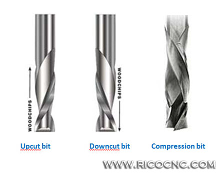
Flute Geometry :-Upcut, downcut, straight cut, and compression. Up-cut, down-cut and compression cut determine the way the chips (cut material) are ejected and the smoothness of the surface. With an up-cut end mill, the chips will be ejected upward and the bottom of the material will be smooth. The down-cut end mill is the reverse by puching the chips downward and the top of the material is smooth. The compression end mill creates a smooth surface on top and bottom, which is perfect for pre-laminated woods.
-
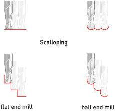
Shape of the endmill : A ball nose end mill, also known as a spherical end mill or ball end mill, has a semisphere at the tool end. Flat end mills will cut flat areas with no scallops. However, they leave a terrace-like scallop on non-flat surfaces. Ball end mills will leave smaller scallops for the same stepover value on sloped surfaces, but they will also leave scallops on flat areas.
 Source: https://wiki.imal.org/howto/cnc-milling-introduction-cutting-tools
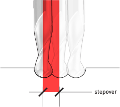
 - Stepover: It is the distance moved by the tool over subsequent passes.The stepover value (along with tool size) will determine whether the model has a smooth finish, or tooling marks are visible. It will also directly impact cutting time. Models with a smaller stepover take longer to cut.
 Source: https://wiki.imal.org/howto/cnc-milling-introduction-cutting-tools
 -
Stepdown:- The length of the cutting area within the tool determines how deep the material can be cut in one operation –this is called the maximum stepdown. This stepdown value will only be used to its maximum when the material that is being cut is soft; for harder materials a smaller value is often required, setting the toolpaths to mill away layers of materials in separate passes.
-
Runout: Run out is differences or variations in the diameter of a cutting tool at certain points along the outside edge while the tool is rotating. When an end mill is in rotation it is important that each tooth hits at the exact same spot along the work piece. If one tooth is hitting the work piece more than the others then that tooth is doing the bulk of the work. This will cause the end mill to wear and breakdown more quickly.
-
Cutting parameters:- The basic cutting parameters are spindle speed and plunge feed. Though I found sufficient material on this , I understood that too much calculation is behind in fixing the optimum feed rate and spindle rate. It is a function of chipload, flute number etc. Calibration charts by the manufacturers of endmill is helpful in fixing these.
 Source: https://wiki.imal.org/howto/cnc-milling-introduction-cutting-tools
Assignment 1 - Finding the machine milling parameters and machine settings
Considering these above parameters an ideal choice with regard to the type of work, material type, endmill geometry etc can arrived at for our job. The cutting parameters like spindle speed and feed rate have to be selected cautiously as a slow rpm wont cut the material and delay the job. While putting the machine on a high rpm will produce more heat on friction and may increase the chances of fire.
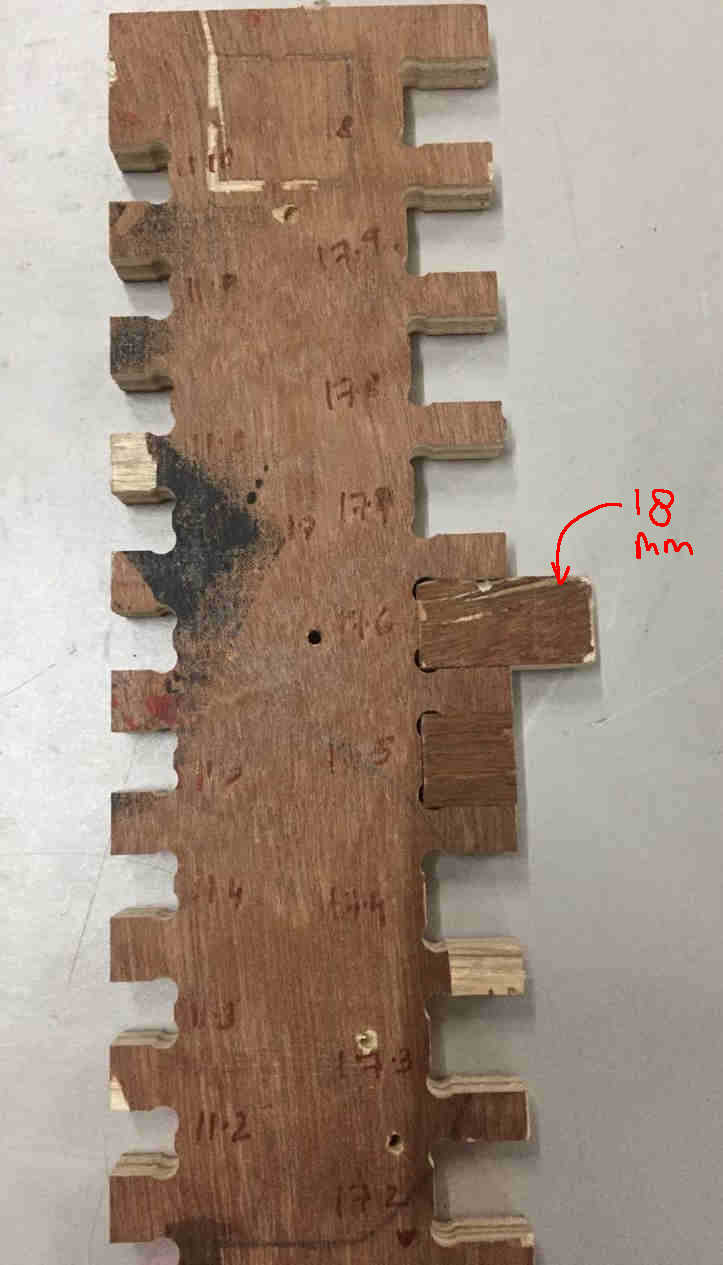
Since we would be using either 12mm or 18mm Veneer Plywood, we made a slotted scale to test our cuts. On one side slots for 12mm and 18mm was designed and incrementally made. Our aim was to find the tool path, feed rate, spindle speed, and fit for the plywood. We used custom settings as below
Spindle Speed : 11000 rpm
Feed rate : 20 mm/s
Endmill size: 6mm single flute
Toolpath: Profile Cutting for outside boundaries and Pocket cutting was resorted for checking the Upcut and down cut.
Passes: 3 passes
Optimum fit slot for 18mm : 17.6mm ie, fit compensation is .4mm.
The dxf image of the slotted bar was imported in V Carve and checked for any open vectors by clicking join open vectors.Machine vectors were selected as outside for cutting profile and for the inner holes/slots inisde cutting was resorted for preventing loss of material from our design. Also number of passes are to be specified for acheiving the desired depth of cut.
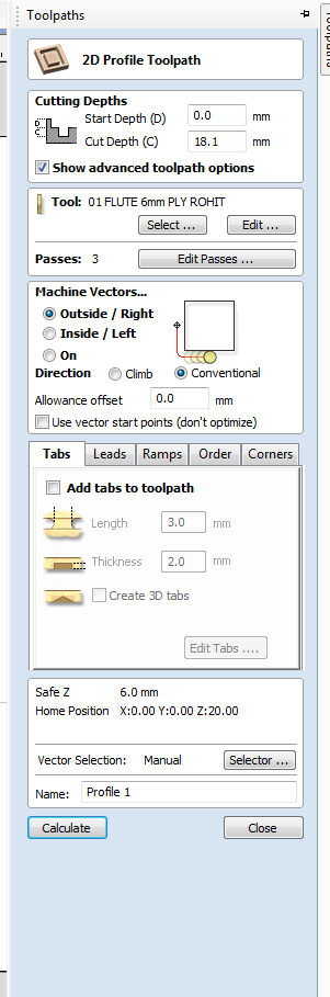
Specifying the tool path. For cutting insides out from the board the path for the tool is put to inside. For cutting out from the outside Outside tool path is selected. The direction of cut is selected as Conventional.
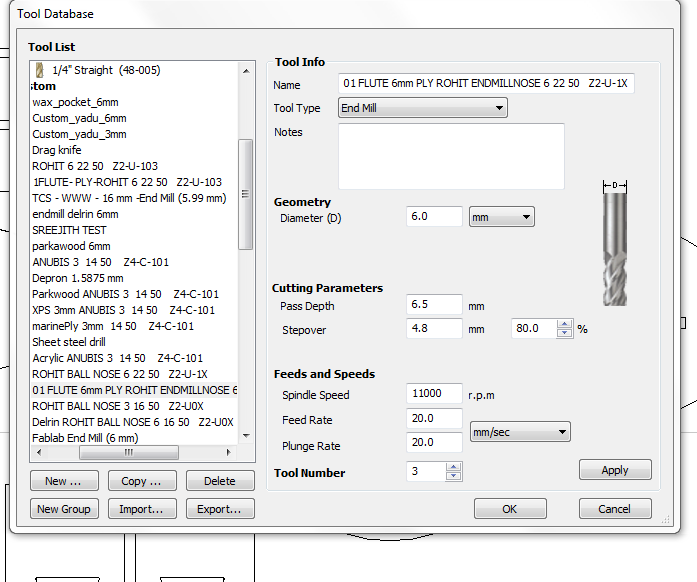 Selecting tool from the database
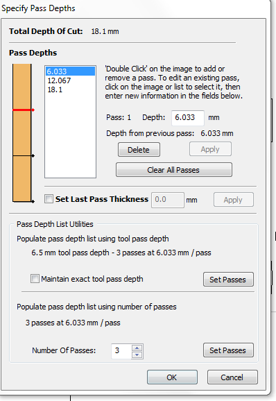
Specifying the number of passes
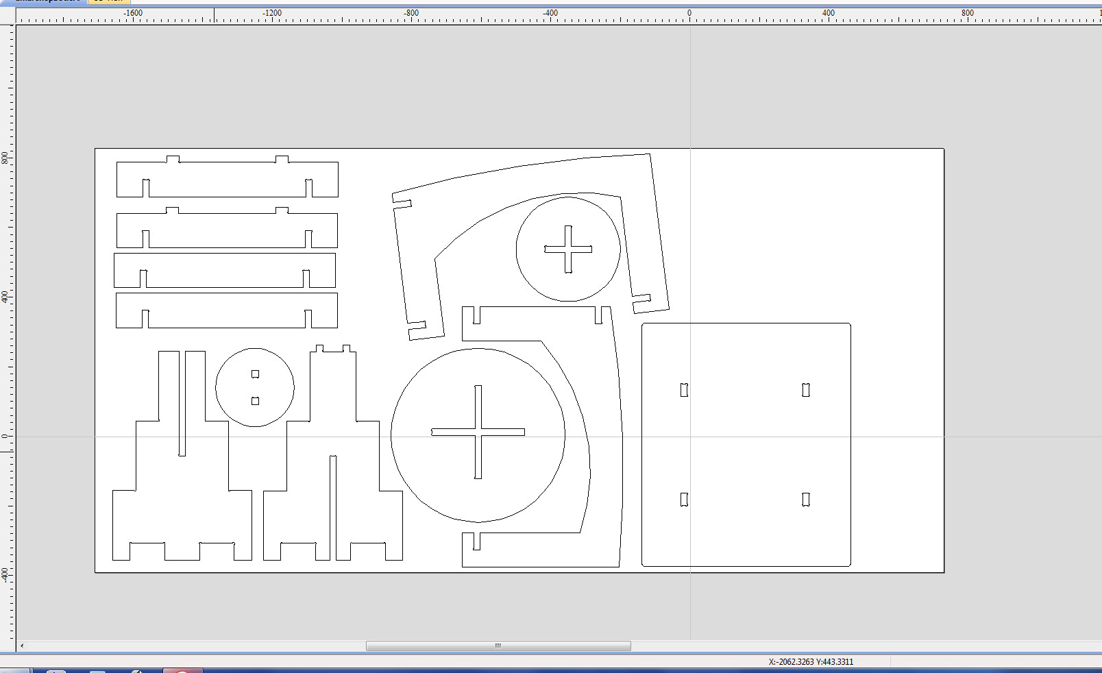 Mine and Amal’s cut outlines are optimised to save the material.
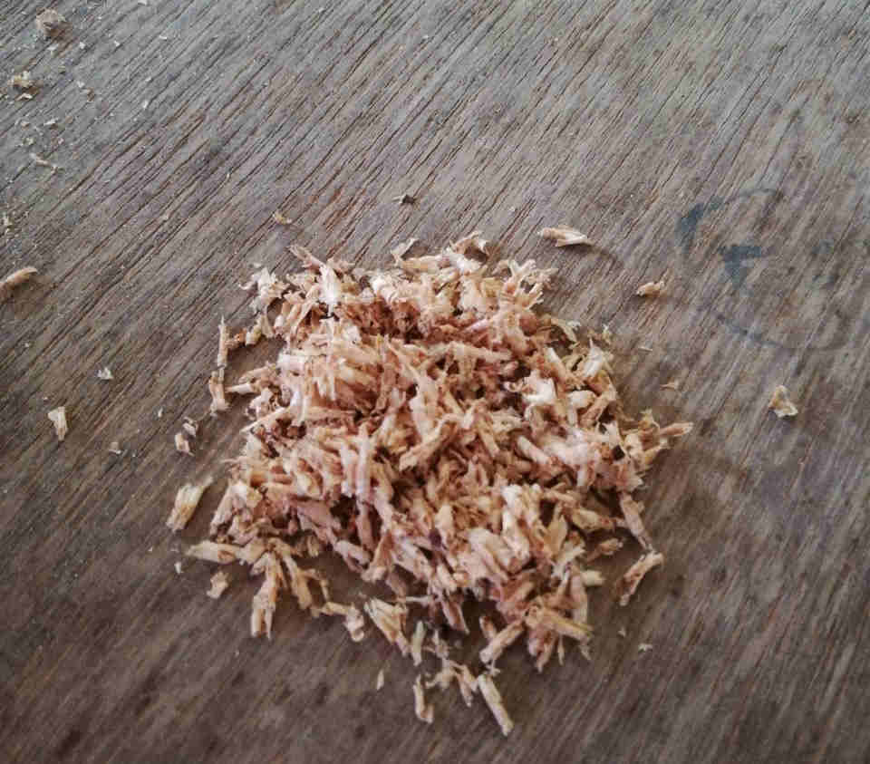 We can see that the chips are not powdery, rather big and grainy, as it came out really smooth, we can infer that the choice of this endmill is ideal for our work.
‘Dogbones’ and ‘Tabs’
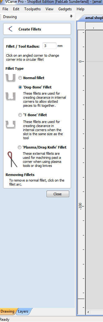
Dogbones were provided at every inside corner of the cutting outline. Since the tool tip has a round profile, it causes the square corners to loose some portion if we don’t account for this. Dogbones are provided in Fillet option to give space for the circular tool tip around the corners. Also Tabs are to be provided to prevent the breaking away of the cut parts in final passes around a closed cut path. These tabs will help to hold the whole cut part in position and prevent them from breaking off by leaving small thickness and length uncut.
Finally after fixing the cut parameters using V-Carve the cutpaths and tool path can be previewed and animated before being saved as sbp file, a standard syntax tool path and instruction code for the Shopbot.
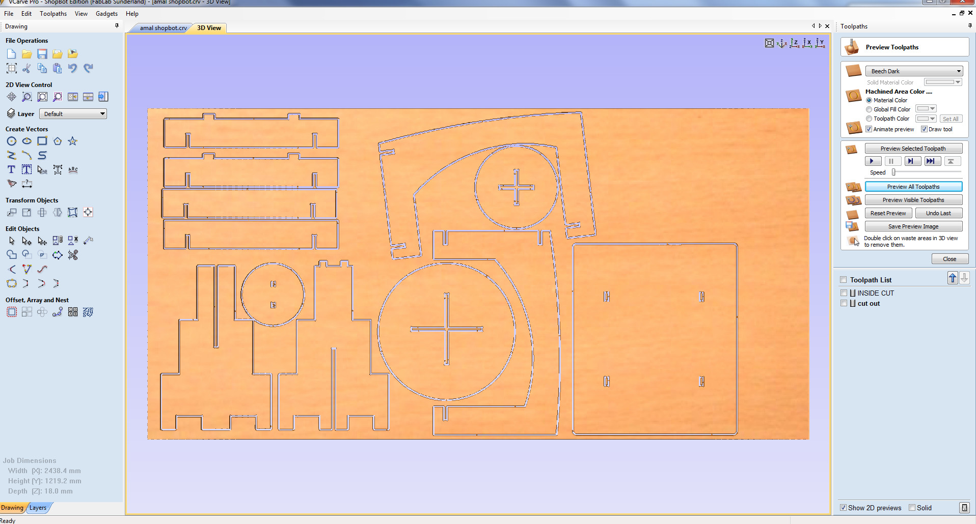 3D cut preview
Machine Operation
-
The endmill has to be connected to the collet and then tightened using collet screws. It should be ensured that the endmill is tightened well or it will cause damage to the bit in operation.
-
Before making the machine move the spindle axis is turned on and kept for sometime. During this time it shall be ensured that the spindle achieve the desired rpm. Also warming up will enable the lubricants are sufficiently circulated well before the real operation.
-
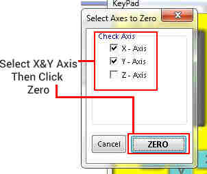
The default machine coordinates are set to zero using control software. When it is set the machine will move and come to this coordinate. However for our job a seperate zero coordinates can be set using control dialogue box.
Z direction zero is set using zero axis plate.To set zero on Z axis the zero axis plate is kept horizontal in the bed. By ticking the Z axis in the zero axis dialogue box, the machine spindle will move and come down and touch down. This will happen twice and we will get the message in the screen that the machine Z axis zero is set.
When the machine is in operation we can see the machine control terminal with machine coordiantes changing. It can be paused by pressing space bar in the computer. Once paused the machine can be resumed.
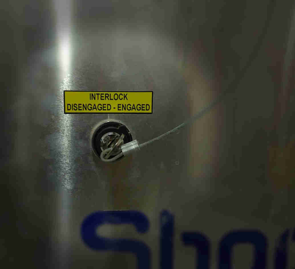
- In case of emergency the machine can be stopped using the red push buttons on the side of machine and near the computer. Stopping using emergency stop button wont resume the operation, hence it is advisable that it is used only in case of real emergency.
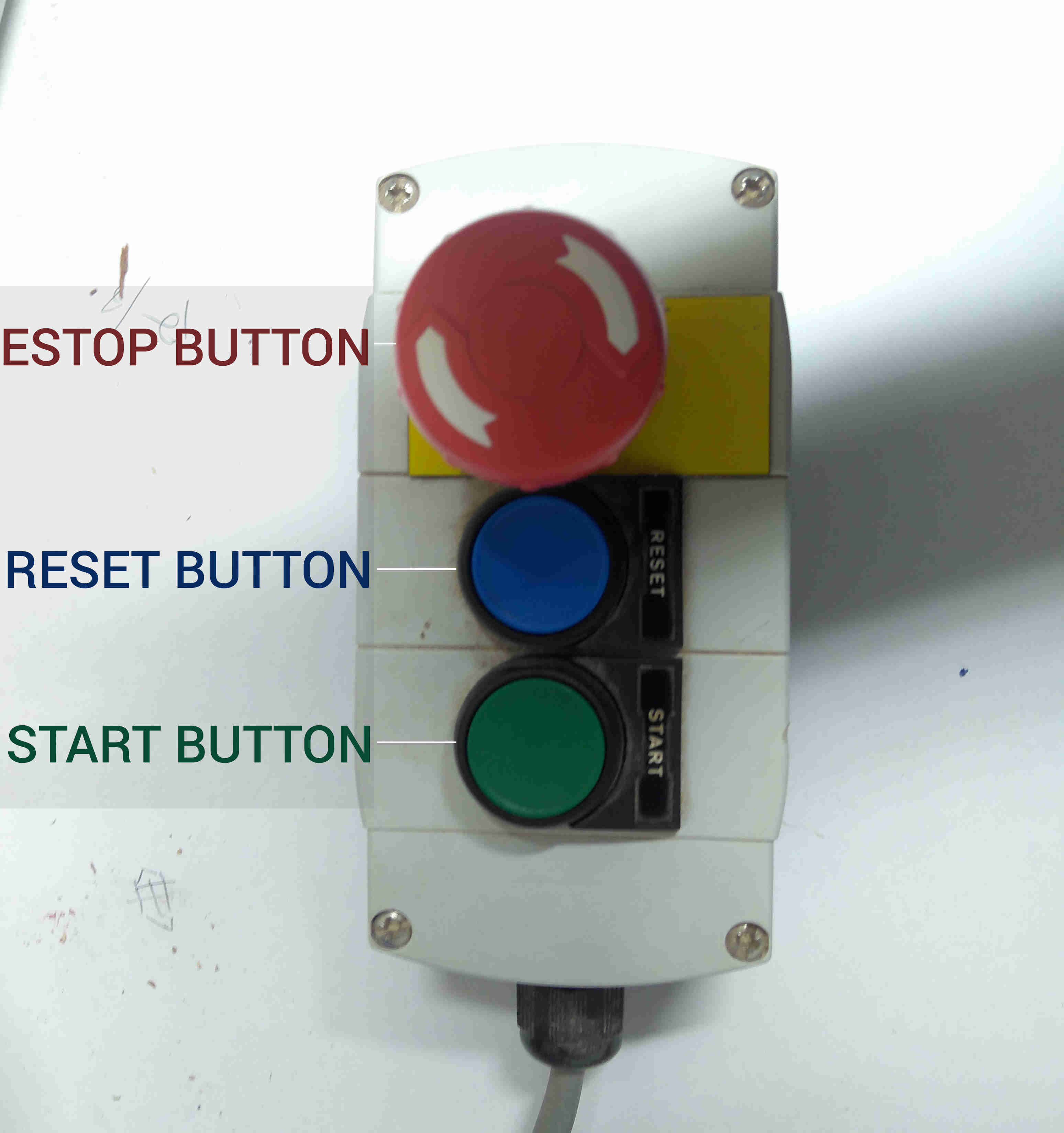 Control button
 Key to start the machine
Setting zero
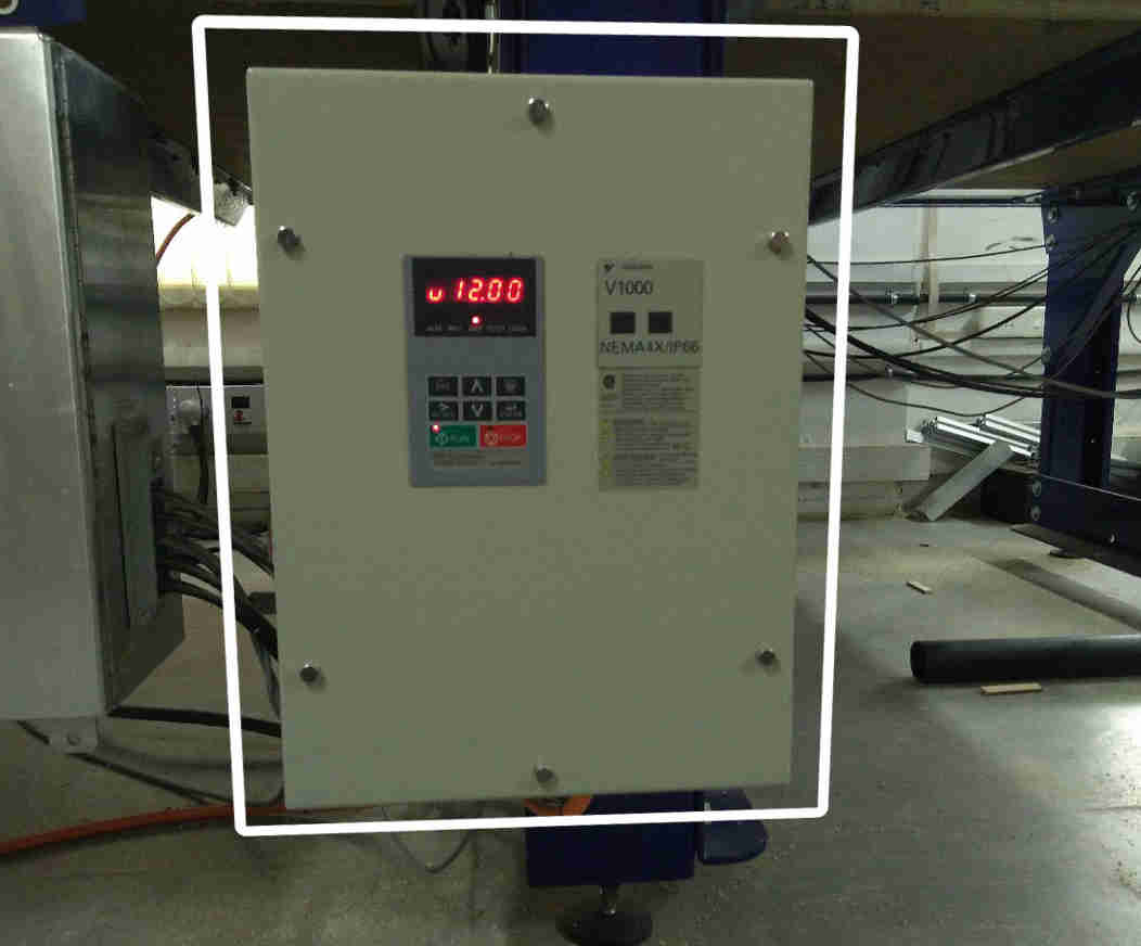 Controller beneath the machine to control spindle rpm and motion manually
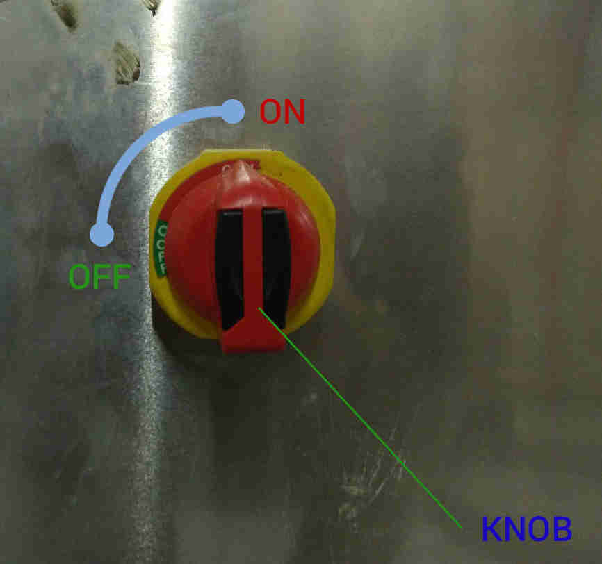
On/Off knob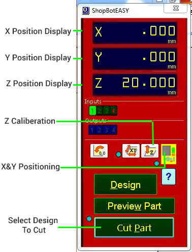
Control for machine motion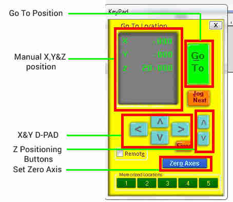
Manual motion of machine Courtesy: http://archive.fabacademy.org/2018/labs/fablabkochi/students/suhail-p/
Precautions
-
Check that the cutting bed with the stock is free of any tool or anything before the start of operation.
-
Wear shoes,gloves,masks and goggles and ensure that no one reaches into the machine , when it is in operation.
-
Machine shall never be left unattended in operation. Atleast two people shall be there during the operation.
-
Stock is usually screwed onto the sacrificial layer, it is to be ensured that sufficient clearance is kept between machine head and these screws.
The real action!
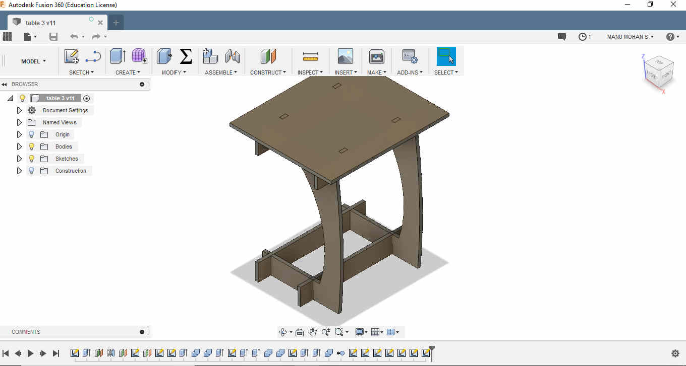
Assignment 2 - Making the Study table
I had decided to make a small study table for my wife. A simple design was adopted. The preliminary dimensions were sketched in the notebook.
The drawings were modelled in Fusion 360 and exported as dxf files. The design was made parametrically so that I could tweak with the dimensions after the modelling process.
Though this was CNC week the thing I learnt most was modelling in Fusion 360. I really learnt the benefits of parametric design and understood how a single Sketch can be continously used and manipulated to generate multiple connected 3D elements.The commands like Combine to generate slots and Offsetplane came really handy in generating this. How meticulously we can keep building our model by building bodies and components. I really can’t thank Rahul Rajan, Kerala Startup Mission enough, who helped me countless times whenever I stumbled upon with designing issues. Such a wonderful software it is !.
After cutting, the edges of the parts were filed and smoothened to make it fit.
Fusion Files
Shopbot Files
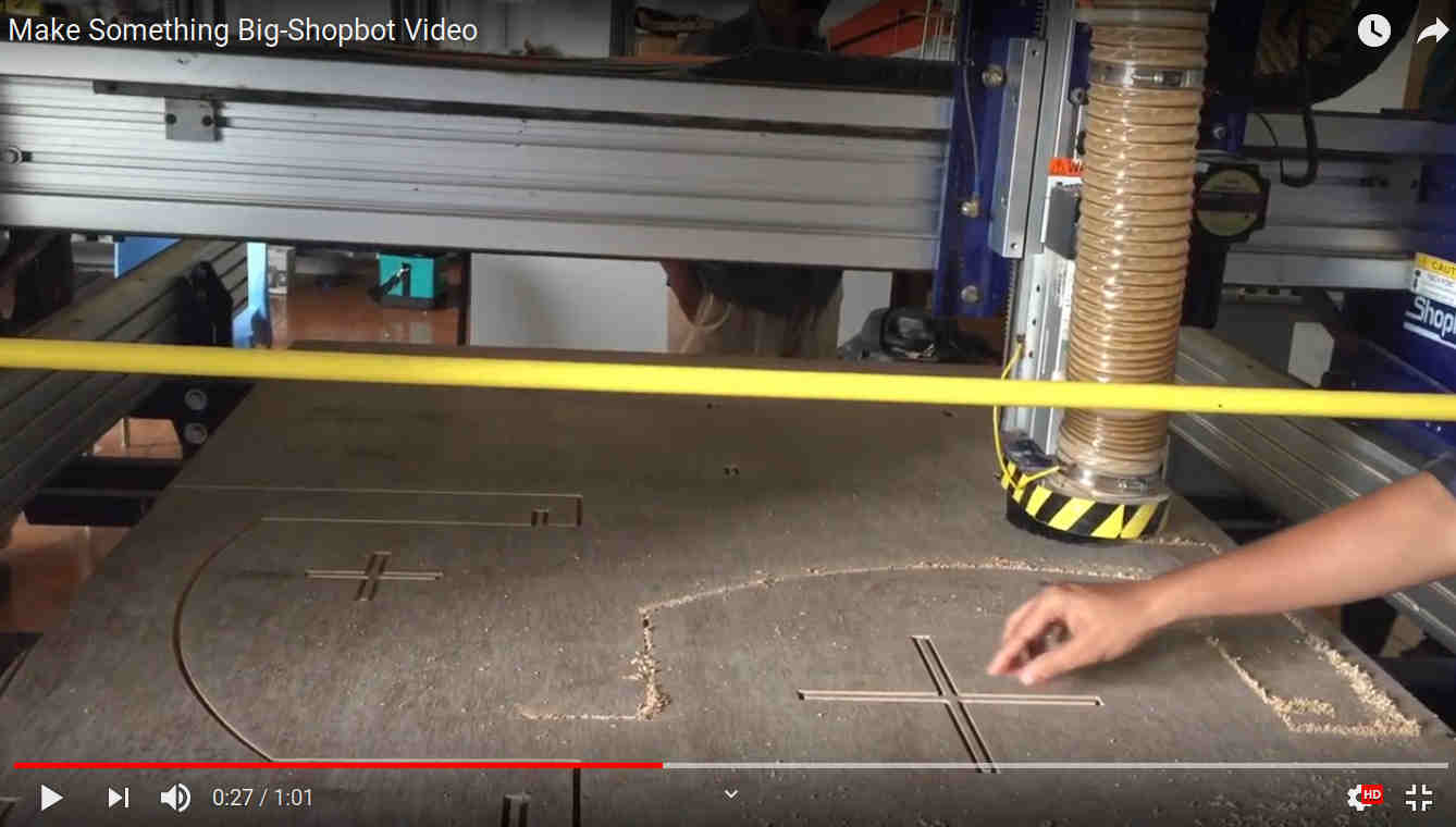 Working Video
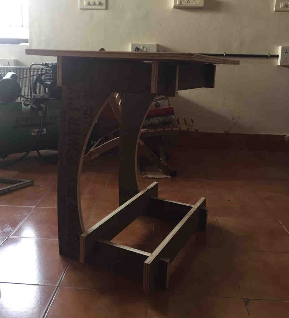 The feeling was amazing that I could make something that I had designed and dreamt of !
Issues
-
The table was little higher than I expected, I could have been more cautious with the dimensions. Since the time was running out I was bit nervous to finish the cutting faster. The lesson was that a little patience will always pay off.
-
I forgot to check that the slots were formed at every place. I missed those at the base at two points. Fortunately the since the connecting elements had slots I could assemble without any issue.
-
Though the parameter for fit compensation was added in the design, I forgot to add values found from the group assignment. This made my job really difficult during the assembly process. It was really difficult filing and smoothening out the edges to fit the parts.
References
- https://makezine.com/2014/09/10/endmills/
- https://inventables.desk.com/customer/en/portal/articles/2850808-carving-bits-101—bit-basics
- https://en.m.wikipedia.org/wiki/Milling_cutter
- https://wiki.imal.org/howto/cnc-milling-introduction-cutting-tools