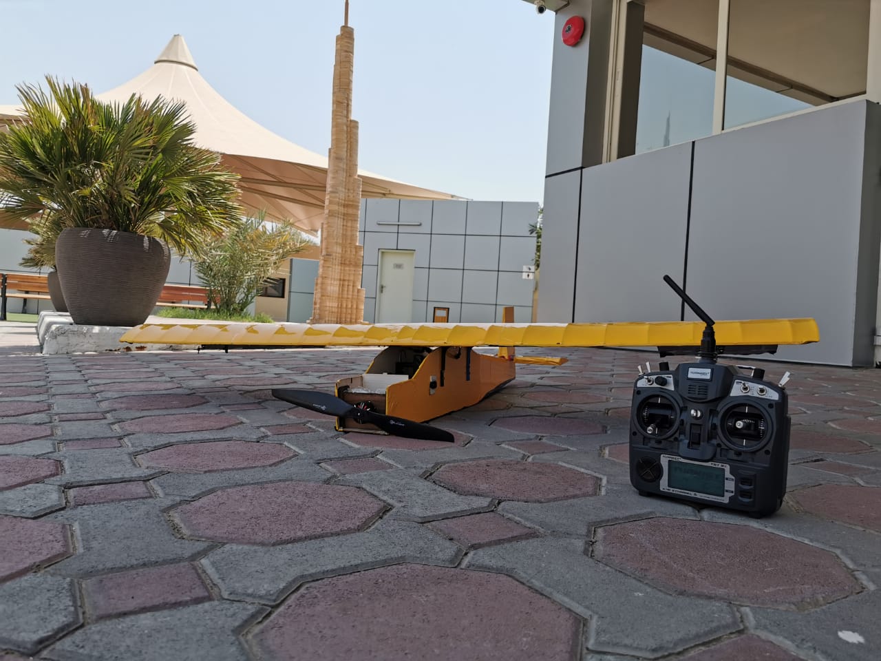
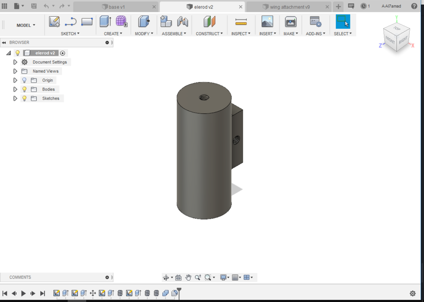
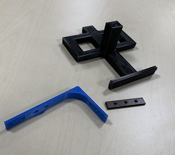
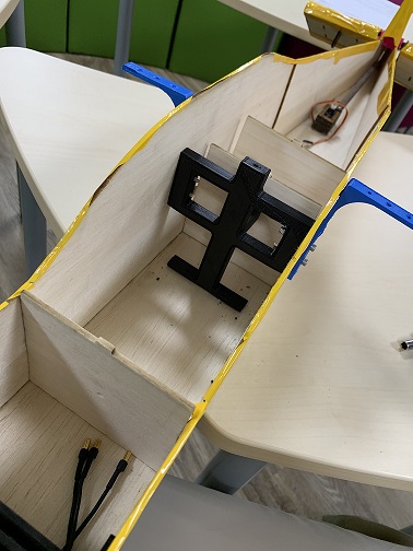
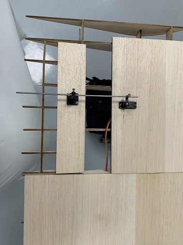
FABFLY is a RC aircraft , that have several inputs and outputs , and the new function that I tried to put is that while flying if I didn’t move the stick in the transmitter , it will try to balance it self , and the accelerometer will help me with that , so the aircraft build from balsa wood and attached with some 3D printed parts and covered with a material called monokote , which will help in reducing the weight of the aircraft .
this is a video of one of the first aircraft I built and flow.
in this project all what I did buy is the Balsa wood and the monokote which cost me around 55 $ ,so all the other materials I found it available in the lab , this is what encourage me to make this project ,however the materials that I used in my project are the following :
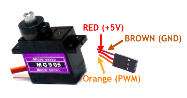
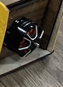
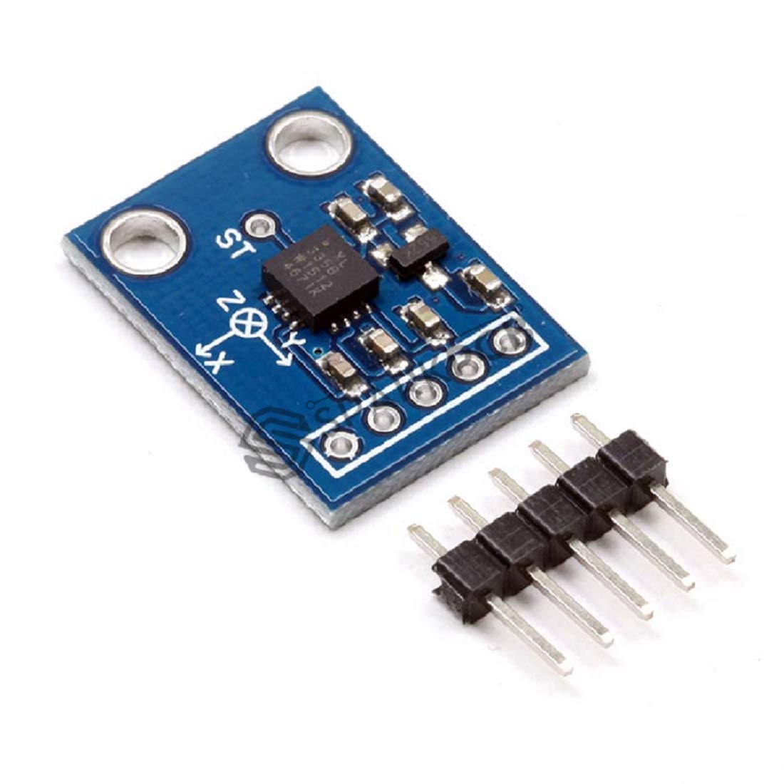
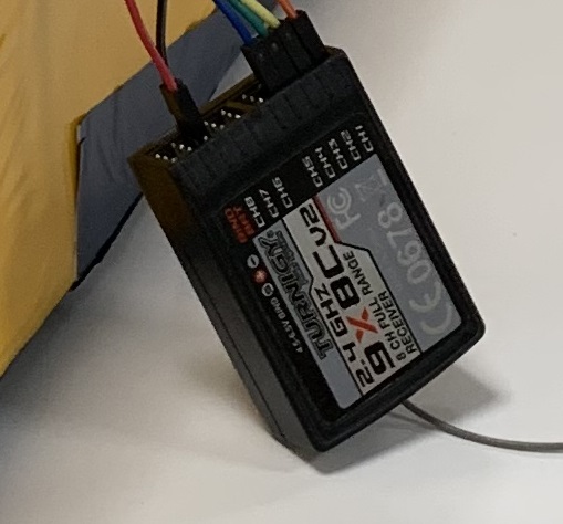
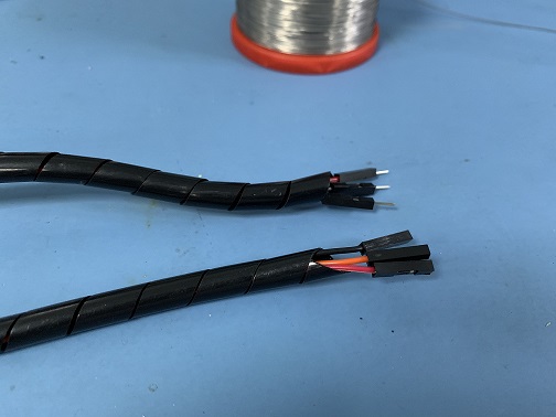
so in the aircraft there are some movable parts that will control the movement of it , on my aircraft I have , two ailerons , elevator , and motor , you can find more about the movement surface on this page, however I used 3 Servos on my project and one motor with ESC as an output from my PCB , and my inputs are , the accelerometer , transmitter and receiver , so the servos were controlling the ailerons and the elevator , to move them up and down , and of course we control the brushless motor with ESC to varies the speed .
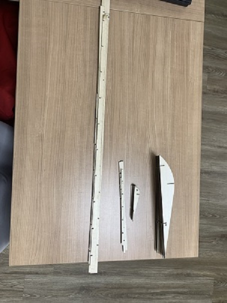
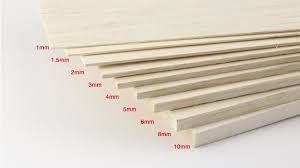
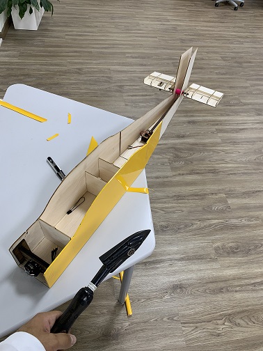
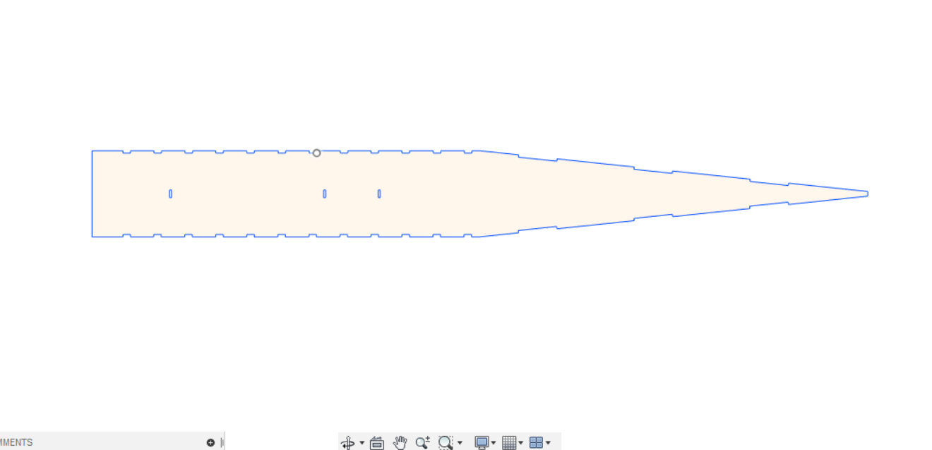
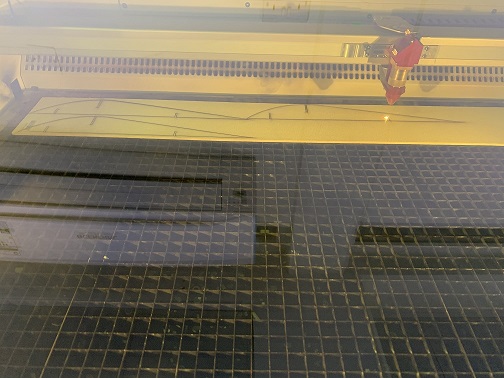
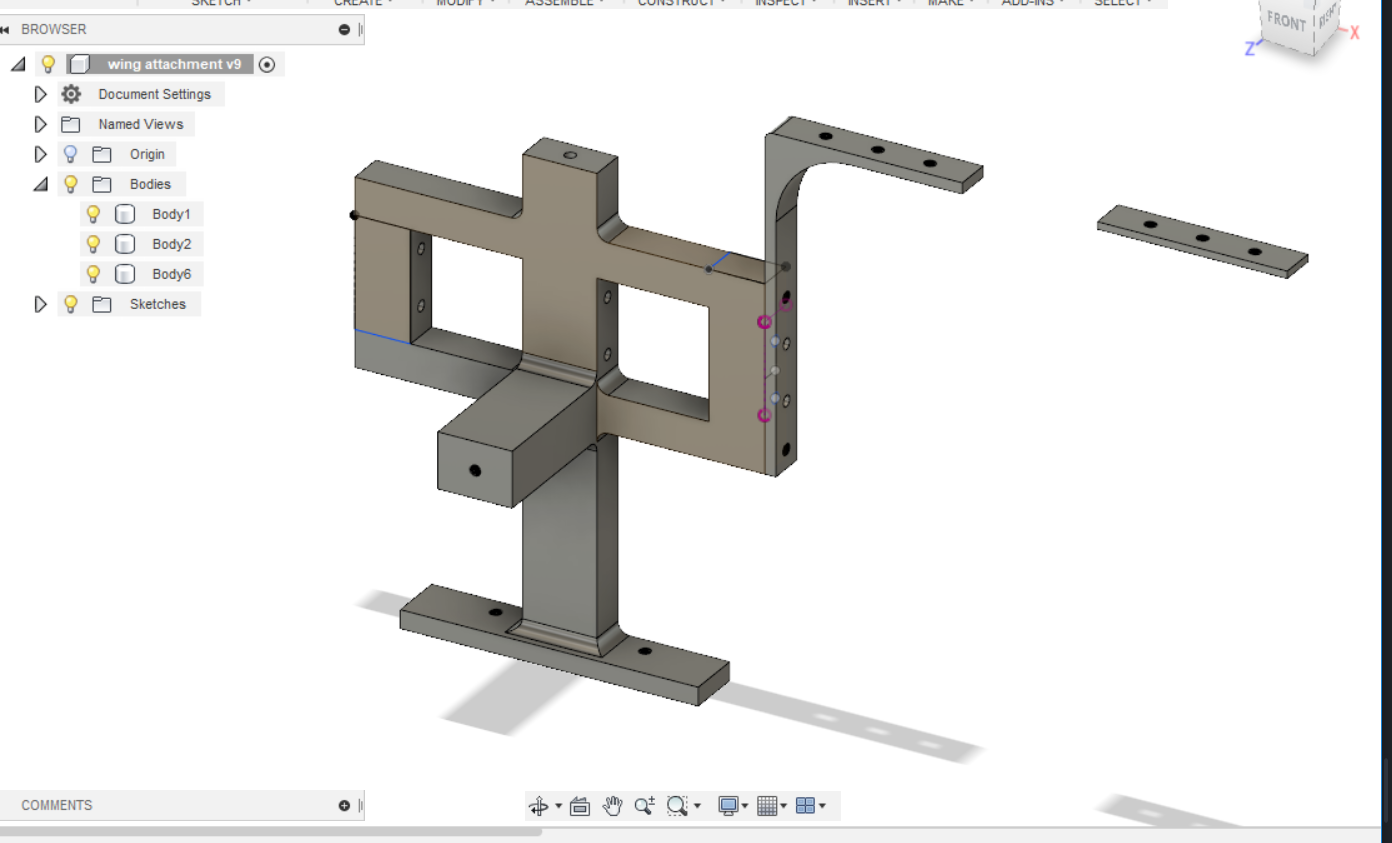
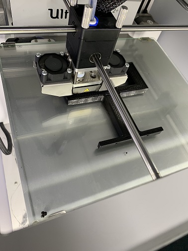
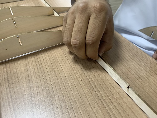
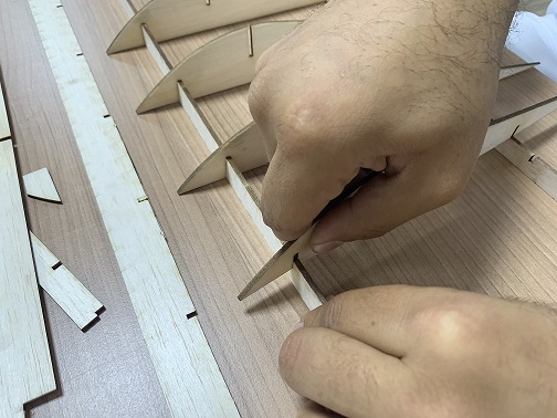
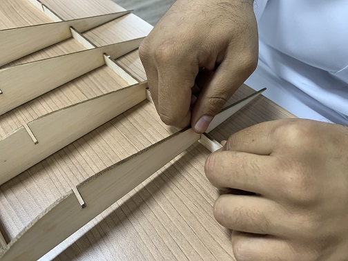
so my first step was to design and laser cut my wing and body , however I faced some problems with finding a balsa wood in the first stage , but I managed to get it , how ever after I finish designing , I started to test the wood while cutting , trying to find the kerf so my wing will be a press fit design , after a long time of testing because the balsa wood is soft and easy to break , I found the best kerf that I can use , to assemble the wing without breaking the wood , the kerf was 0.3 .
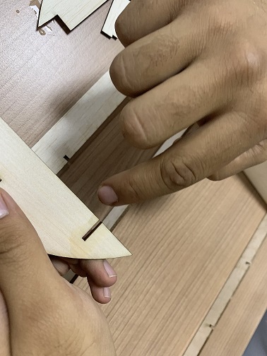

So all what I experience and learnt in week6, helped me a lot to achieve this.
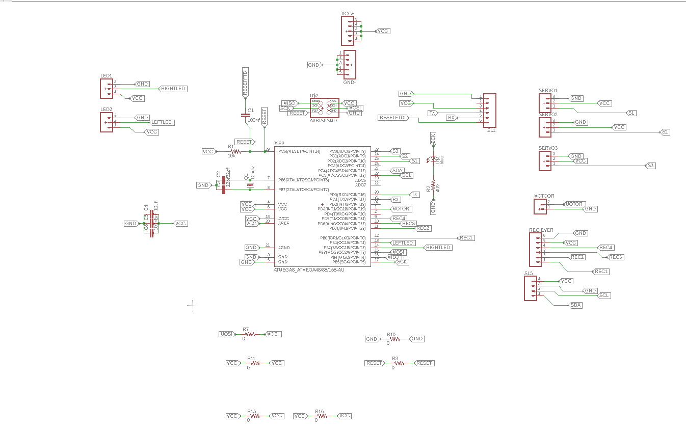
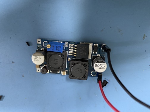
In addition , I used a step down , to regulate the voltage that will enter the PCB , from the Lipo Battery , to make sure that my BCP will not damage , because the voltage from the battery is 11 V , and the BCP only need 5 V .
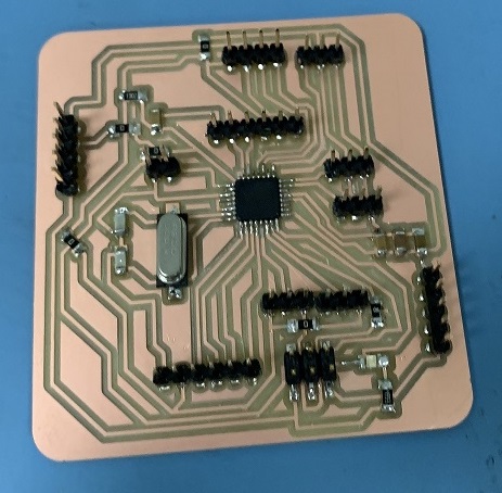
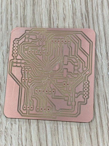
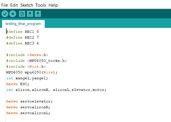
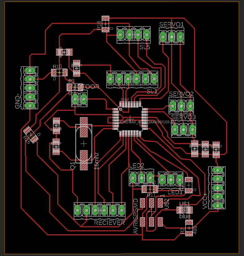
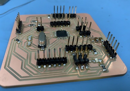
the most interesting part in my project is the Programming , which I learnt a lot on this stage , and it was fun , so to program my board , I used attmega 328p , which will help in reading PWM signals from the receiver , and it has the servo library as well , However I used my testing in week11& week12, to make sure my BCP is working , and then I started to write my code step by step , First by reading the serial from the transmitter to know the input range that I will use to map my servos and motor , then I read the accelerometer inputs and calibrated as well , actually , I would thank Daniel , and Hashim ,the mentors in FAB LAB UAE , it was a great chance to get some of their experience .
so this is my code :
#define REC1 8
#define REC2 7
#define REC3 6

#include <Servo.h>
#include <MPU6050_tockn.h>
#include <Wire.h>
MPU6050 mpu6050(Wire);
int xangel,yangel;
Servo ESC;
int aliron,alironR, alironL,elevator,motor;

Servo servoelevator;
Servo servoalironR;
Servo servoalironL;

void setup() {
  // put your setup code here, to run once:
  ESC.attach(3,1000,2000);
  pinMode(REC1,INPUT);
   pinMode(REC2,INPUT);
    pinMode(REC3,INPUT);
  Serial.begin(9600);
   servoelevator.attach(A2);
   servoalironR.attach(A1);
 servoalironL.attach(A0);

 aliron=0;
elevator=0;
motor=0;
alironR=0;
alironL=0;

servoelevator.write(90);
servoalironR.write(90);
servoalironL.write(90);

Wire.begin();
  mpu6050.begin();
mpu6050.setGyroOffsets(-6.31, 0.8, 0.39);
}

void loop() {


 aliron=pulseIn(REC1,HIGH);
   elevator=pulseIn(REC2,HIGH);
    motor=pulseIn(REC3,HIGH);

mpu6050.update();

if(aliron>1550 or aliron < 1450){

alironL=map(aliron,1500,2000,45,135);
alironR=map(aliron,2000,1500,45,135);


servoalironR.write(alironR);
servoalironL.write(alironL);

Serial.println("manualx");


}else {

 xangel= mpu6050.getAngleX();

 alironL=map(xangel,-15,15,45,135);
alironR=map(xangel,15,-15,45,135);


servoalironR.write(alironR);
servoalironL.write(alironL);
Serial.println("autox");

  }


if(elevator>1550 or elevator < 1450){
  elevator=map(elevator,1902,1087,45,135);
  servoelevator.write(elevator);
  }else{

   yangel= mpu6050.getAngleY();
   elevator=map(yangel,-15,15,45,135);
  servoelevator.write(elevator);
  Serial.println("autoy");
   }


   motor = map(motor, 1047, 1875, 0, 180);
    ESC.write(motor);


Serial.print("REC1: ");
Serial.print(aliron);
Serial.print(" REC2: ");
Serial.println(elevator);
//Serial.print(" REC3: ");
//Serial.println(motor);


  Serial.print("angleX : ");
  Serial.print(mpu6050.getAngleX());
  Serial.print("\tangleY : ");
  Serial.print(mpu6050.getAngleY());


delay(20);
}.
that I used to program my project , and you will find some videos when I am testing my programming below :
it was my last stage of programming .
you can see at the end of the video , that the aircraft did not fly unfortunately , I believe that I need to use a bigger motor , because the motor was small for this aircraft size .
you can see at the end of the video , that the aircraft did not fly unfortunately , I believe that I need to use a bigger motor , because the motor was small for this aircraft size . You will find a lot of people build there own aircrafts , and there are some websites will help you if you want to try and you will find some ready designs as well in this Page.
You will find also all my files in this ZIP FOLDER, and you find the presentation video and picture in this page .

FABFLY done by Abdulla Alhamad is licensed under a Creative Commons Attribution 4.0 International License.