
This week assignment is to build a PCB that connected to an input , and read from it , however after the class immediately I decided to build this PCB and use it for my final project which is fixed wing aircraft , so I will build a transmitter , to help me controls the aircraft , so my whole Idea is building a transmitter that transmit the signals from this board to the other board that I am planning to build in OUTPUT DEVICES WEEK via Bluetooth .
so before I designed my board I drew a sketch to help me identify the components’ that I need to use in my transmitter ,
So the components that I will use are :
So after identifying the components I started to read some of their datasheet like :
* ATMEGA328p.
* 5V REGULATOR.
* CRYSTAL.
Reading the datasheets helped me to configure the best connections for the components , so I started to do my schematics ,setting the components that I need and connect them.


Now my board is ready , but I did a final check by using DRC (DESIGN RULE CHECK) , to check the clearance.


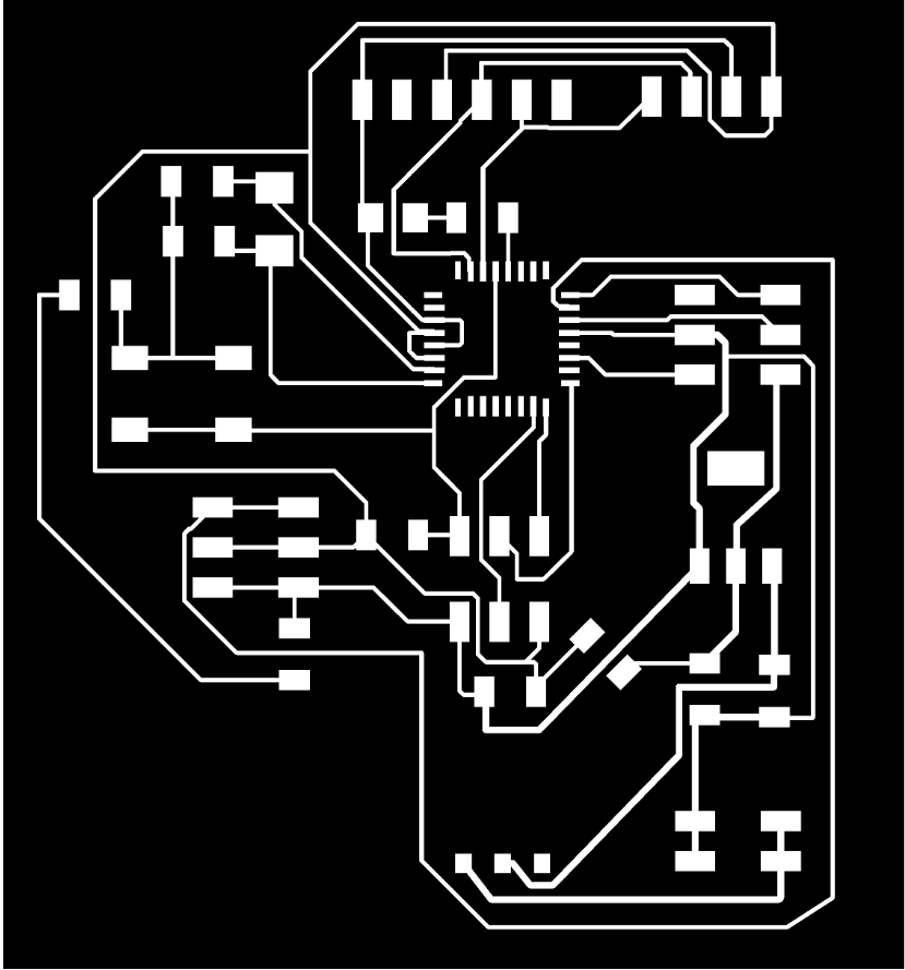
You can see now in this video the final step of cutting the outlines.
However I was excited to finish this board so I forgot to take a photo of it before I started to solder the components .
This my board after the soldering and I did the continuity check as well , so the board is ready for programming .
## PROGRAMMING:
I did not do much in programming , I just wanted to get an idea about the potentiometer programming , and to make sure that my board is programmable, I kept the real program to the end when I will start to work on my final project , so I will write about it in details in my Final project page.
So all what I did , I copied a code from this tutorial , I did some modification , by adding the pin that I will use , and I tried the mapping as well, for the serial read , to know the value that the POTINTIOMETER will give, however you can see that from my schematics that I connect the TX , RX in a wrong way , but I fixed it by flip the connection in my program .

I did test the program on my board and it work perfectly as you can see in the video below :


You can find all my working files on this ZIP FOLDER.