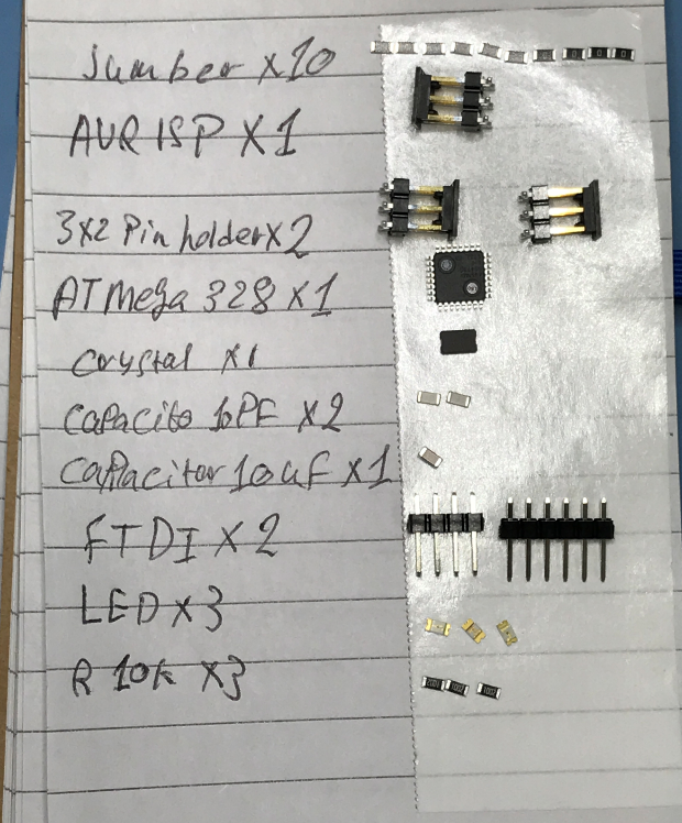
so these are my components list :
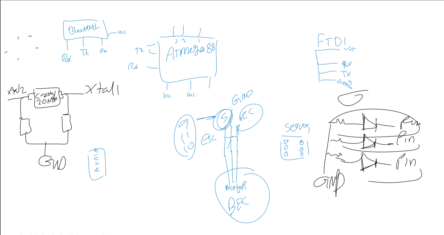
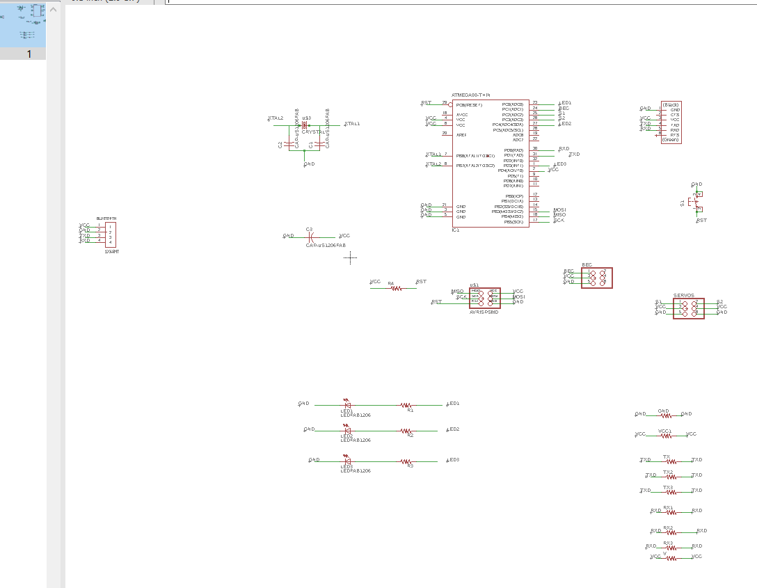
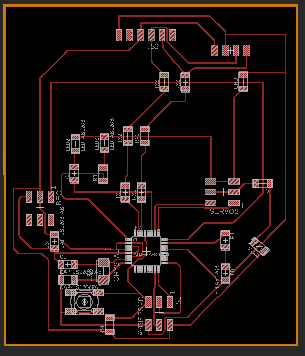
that helped me to understand how should I connect the components, I started to do my schematics using EAGLE.
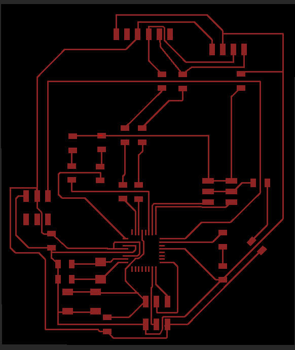
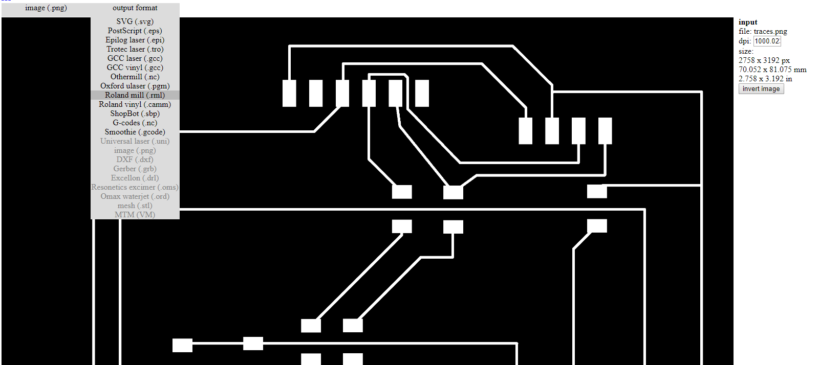
So now I am ready to complete my board by connecting the traces, However I learnt from my last week mistakes , I kept the width of the traces 6 mill , and I used a lot of jumpers to save some time doing it , but I promise my self that I will keep practice how to connect the traces and reduce the number of the jumpers .

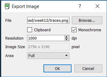
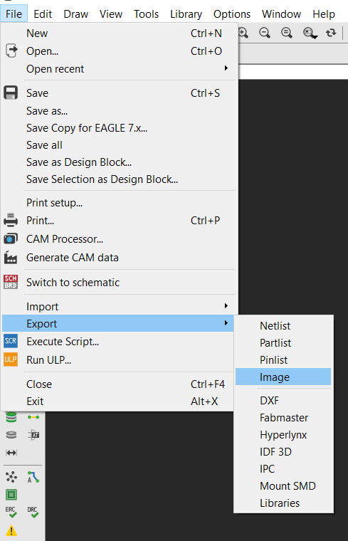
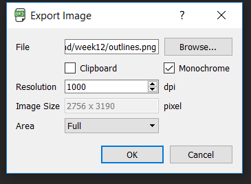
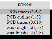
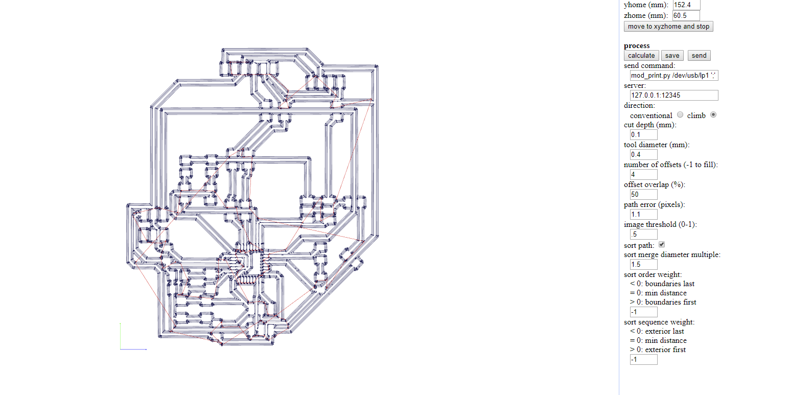
After I did all the checks that I need to make sure that my board is ready to be catted , I saved the design as a PNG , so I can use it in FAB MODULES. I did the same process that I did in this week.then I started to cut the board by using to mill bits with size of 1/64 for the traces , and 1/32 for the outlines.
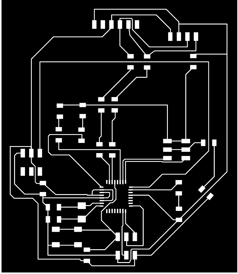


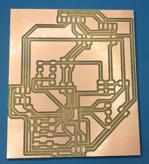
After finishing the whole process of cutting , I started the machine , and I got my PCB board ready.
off course , I started to solder my components immediately , and it was much easier this time , because I practiced a lot.
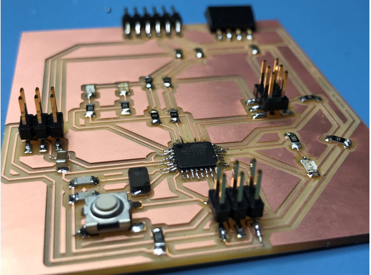
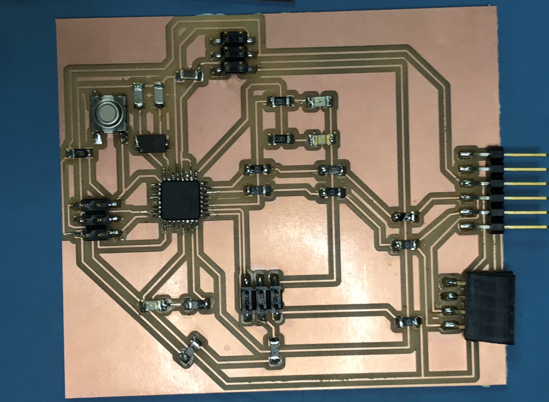
And now my board is ready to be programmed .
for this task my goal was to configure , how the servo is programmed , and to make sure that my board is programmable, because if I reach this goal , I will be able to finish my final project receiver, so I tried two programs . to see how the servo is working , and I did it, my next step will be to connect this board with the week 11 board via BLUETOOTH , and control the servos by the JOYSTICK .
so this is the code that I used to program my board and move the servo from 0 - 180 degrees, which called SWEEP ,I did some changing like , changing the pins and the angles, you can see how it works in this video:
However for this code , I kept the first position is 0 , then it will move to a certain degree , then it will go back to 0 , I believe this code will be useful for my final project as you see in the video , I did a small test to see how it will control the surface .
You will find all my working files in this ZIP FOLDER.