Task required:
We assigned to read a microcontroller data sheet . Program the board that has been done in week7 to do something. In addition, use different programming languages and possible.
what I did ?
After reading data sheet, I programmed the boart to:
- Turn the LED ON and OFF repeated in certain time.
- Turn the LED ON by pressing on the button and OFF if not pressed.
Task Procedure
Reading micro-controller data sheet
The data sheet contains a plethora of detailed information and I’m a beginner in dealing with those data. Furthermore, the session with our great instructors Daniel and Hashim was good enough to guide us where to start and what is the basics. I tried to focus on understanding the major things that could be a base for me to develop. The following information summarizes what I learned;
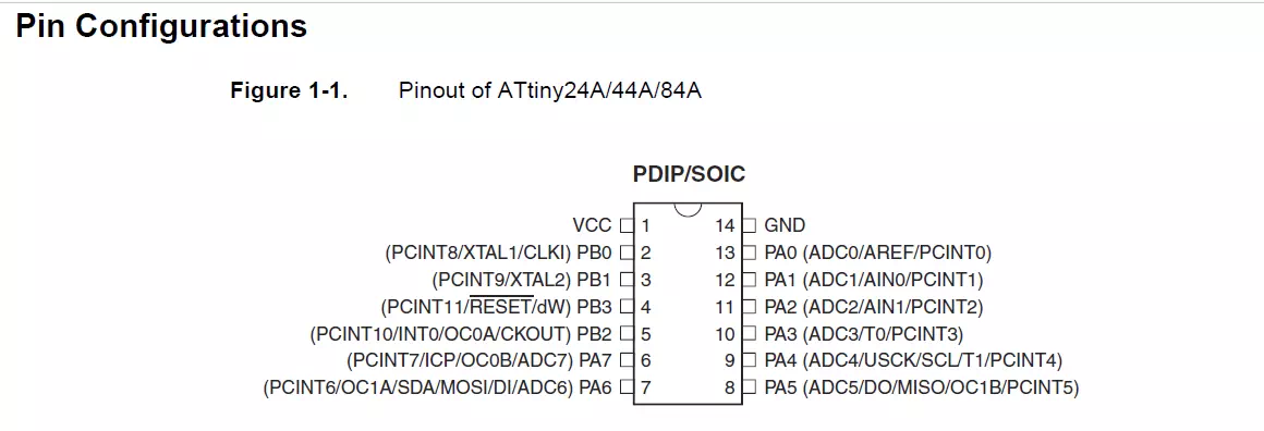
The first important picture in the datasheet was the one below. It shows the pin configuration of the ATTiny44 which is the microcontroller that I’m using in my board..
- • VCC pin: supply voltage
- • GND pin: Ground
- • Port B (PB0 to PB3): 4-bit (0001) I/O port with internal pull-up resistors.
- • Port A (PA0 to PA7): 8-bit (00000001) I/O port with internal pull-up resistors.
LED ON and OFF repeatedly in certain time.
// Mozah Fabacademy2019
//Boton connected to pin 10
// LED connected to pin 5 which is NO.8 in Arduino
void setup() {
  // put your setup code here, to run once:
  pinMode (8,OUTPUT);
}
void loop() {
  // put your main code here, to run repeatedly:

    digitalWrite (8,HIGH);
    delay (100);
    digitalWrite (8,LOW);
    delay (100);
As shown in the code up, LED is connected with pin 8 (PA5=analog pin). By uploading the code, the LED will be ON (digital write is HIGH) and OFF after delay of 100. Then, the cycle is repeated after every 100 delays continuously ON and OFF. If we increase the delay by more than 100 the turning between ON and OFF will be slower.
LED ON only by pressing the button.
// Turns on and off LED connected to digital pin 5,when pressing a pushbutton attached to pin 10.
// constants won't change. They're used here to set pin numbers:
const int buttonPin = 3;     // the number of the pushbutton pin
const int ledPin =  8;      // the number of the LED pin
// variables will change:
int buttonState = 0;         // variable for reading the pushbutton status
void setup() {
  // initialize the LED pin as an output:
  pinMode(ledPin, OUTPUT);
  // initialize the pushbutton pin as an input:
  pinMode(buttonPin, INPUT);
}

void loop() {
  // read the state of the pushbutton value:
  buttonState = digitalRead(buttonPin);

  // check if the pushbutton is pressed. If it is, the buttonState is HIGH:
  if (buttonState == HIGH) {
    // turn LED on:
    digitalWrite(ledPin, HIGH);
  } else {
    // turn LED off:
    digitalWrite(ledPin, LOW);
  }
}
As shown in the code up, the constants are button connected with pin 3 (PB which is digital pin) and LED connected with pin 8 (PA which is analog pin). The variable is pushed buttonState. Then in the pinMode, the LED is considered as output and the button is the input. Thus, by pressing on the button the LED should be ON.
Now, to read the state of the push button which is our variable. First, the button pin is specified in digital read. Next, if statement is used to define if the push button is pressed or not. The LED be turned ON (HIGH) when the button state is HIGH. Otherwise, it will be OFF (LOW).
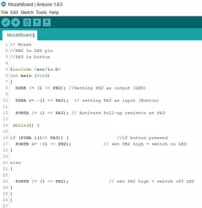
C language
I’m not good programmer but I enjoyed reading and exploring this topic. Here are some informations summarize what I learned about bit manipulation for microcontroller in c language which I used to generate a code.
bit and bytes
When we say Port B in attiny44 has 4-bit it means: 0001 and Port A has 8-bit means 00000001 Note: 8-bits = 1 byte
I/O registers definition
The AVR microcontollers are designed to allow dual use of most of its pins. This has the advantage of allowing a developer to use these pins as I/O pins if the function they are provided for is not being utilized. Also, The pins of the AVR microcontroller are not fixed as input or output at the manufacturing stage, these pins are software configurable which is the topic of the section below.
Atmel AVR is 8 bit microcontroller. All its ports are 8 bit wide. Every port has 3 registers associated with it each one with 8 bits. Every bit in those registers configure pins of particular port. Bit0 of these registers is associated with Pin0 of the port, Bit1 of these registers is associated with Pin1 of the port, …. and like wise for other bits.
Three I/O registers associated:
- • DDRx – Data Direction Register
- • PORTx – Pin Output Register
- • PINx – Pin Input Register
It stores configuration information for the pins of Portx. Writing a 1 in the pin location in the DDRx makes the physical pin of that port an output pin and writing a 0 makes that pin an input pin.
Example:
• to make all pins of port A as input pins : DDRA = 0b00000000;
• o to make all pins of port A as output pins : DDRA = 0b11111111;
It stores the logic values that currently being outputted on the physical pins of Portx if the pins are configured as output pins. So to write values to a port, you write the values to the PORT register of that port.
It stores the logic value, the current state, of the physical pins on Portx. So to read the data from port pin, first you have to change port’s data direction to input. This is done by setting bits in DDRx to zero. If port is made output, then reading PINx register will give you data that has been output on port pins.where x = GPIO port name (A, B, C or D)
Now there are two input modes. Either you can use port pins as tri stated inputs or you can activate internal pull up. It will be explained shortly.
Example :to read data from port A:
• DDRA = 0x00; //Set port a as input
• x = PINA;//Read contents of port a
Useful refrences I used :
Tutorial about avr microcontrollers
Tutorial about I/O programming