Computer-Controlled Machining
- Salem AlMarri
- Super FabLab UAE
- Last Reviewed on 20/3/2019
- Last Modified by Salem AlMarri
Introduction
In this week, something big must be made using a CNC machine. This week combines several skill sets learned through FAB Academy such as CAD design, parametric design, press fitting/joinery etc.
Fusion 360
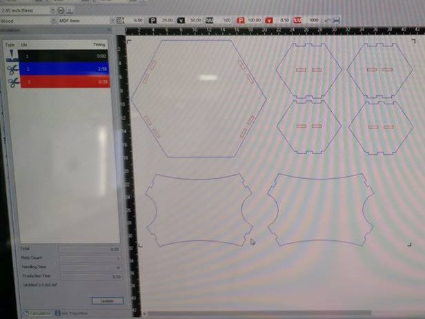
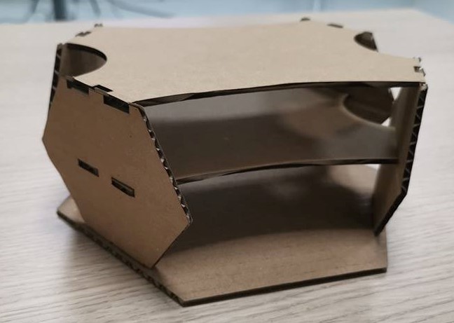
Designing the 2D object was made using Fusion 360. The design consists of a base, four side panels and a shelve.
Cardboard Test - Laser Cutter
Designing the 2D object was made using Fusion 360. The design consists of a base, four side panels and a shelve. This test is important as the time taken for a laser cutter to process and cut this design on cardboard material is very little compared to the time required to cut the design on wood using CNC machine.
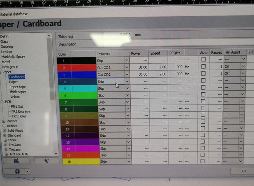
Configuring cardboard settings in terms of color, power, and speed.
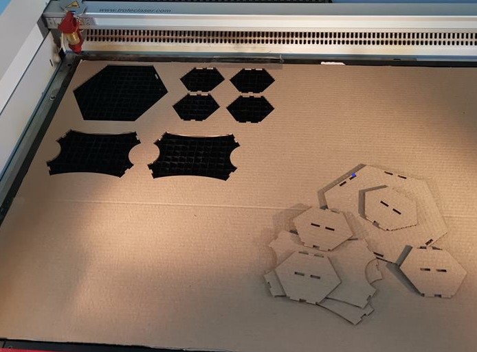
Using a laser cutter, the following cut was produced in a time of less than 3 minutes.
CNC Machine - Preparation
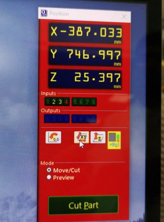
The machine used for this assignment is ShopBot. The machine axis must be set to zero before cutting.
Zeroing X/Y Axis: This CNC machine required zeroing X/Y axis, also the zeroing can be made according to the size of the material used, but this is optional.
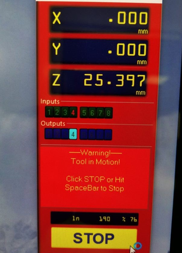
X/Y axis zeroed: X and Y axis have 0mm values, this confirms the zeroing of those axis have been successful.
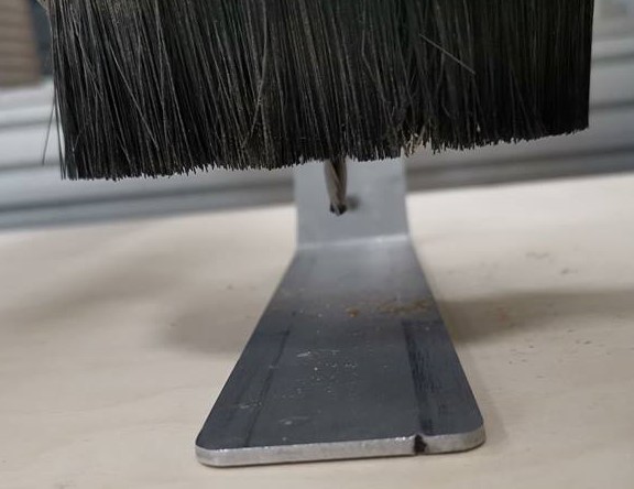
Checking the Milling Bit From Both Sides: Physically confirming the zeroed axis.
It is important to verify from both sides.
Zeroing Z-Axis Required a Metal Plate: To zero the z-axis, the process is different and it requires a clip and a metal bar.
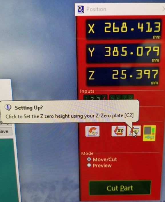
Clip must be connected to a metal part of the machine.
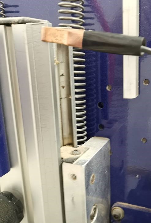
The metal part which must be positioned under the milling bit. Once the process of zeroing z-axis is started, the milling bit is slowly moved towards the metal part until it touches it. This way the z-axis is zeroed.
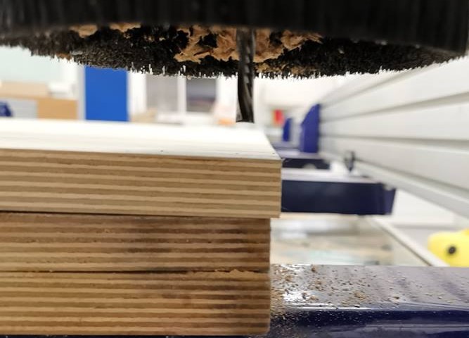
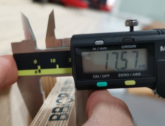
Checking Wood Sheet Thickness ~18mm: It is important to physically confirm the thickness of the material and put this data in the parametric design were the joints dimensions are automatically adjusted in accordance to the material thickness.
Wood Sheet Must Be Fixed Using Screw: Circles appropriate to the dimension of the screw must be added all over the sheet of wood on VCarve software. The pathway must then be saved and executed, once the CNC completes milling those holes, then with a drill a screw can be placed on each hole to fix the wood sheet on the CNC machine.
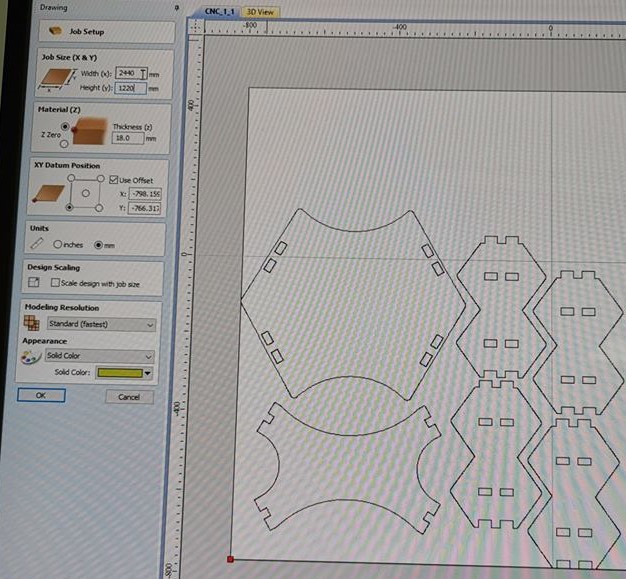
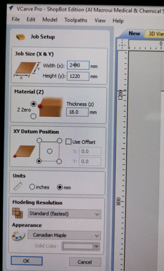
Specifying Wood Sheet's Dimensions: The job size is made to match the wood sheet's dimension of 2440 mm x 1220 mm
2D Cirlces Added Around The Sheet
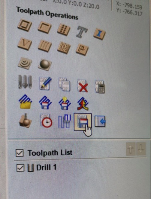
Drilling Toolpath: The setup for drilling toolpath for all the circles around the sheets which would be screwed using a screw driver. The depth of cutting will be 5mm. (our sheet thickness is 18 mm)
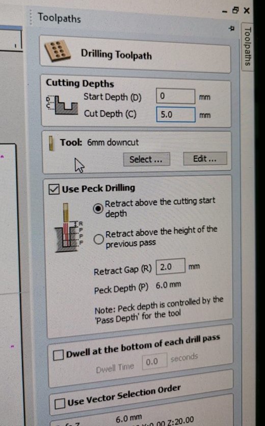
Saving Drill Pathway: With this button the pathway can be saved as a pathway file which can be used by the machine.
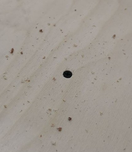
Screw Placed On the Sheet
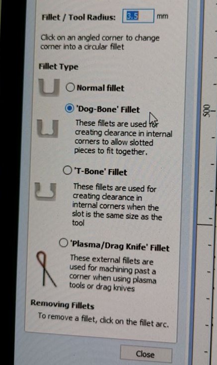
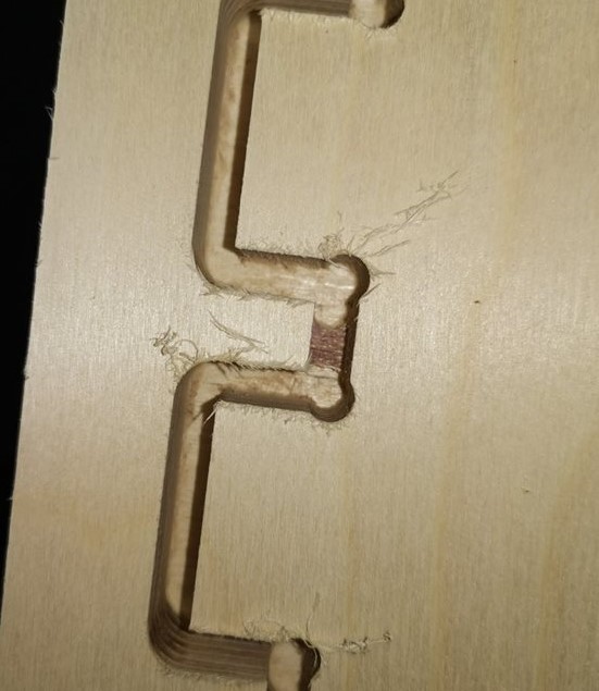
2D CNC Machine's Milling Bit Limitation Require Dog Bone Fillet for Inside Cutting: CNC machines have limitations when it comes to outside cutting on a 90 degrees pathway. The solution is to use 'Dog-Bone' fillet.
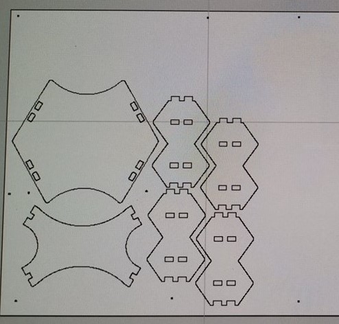
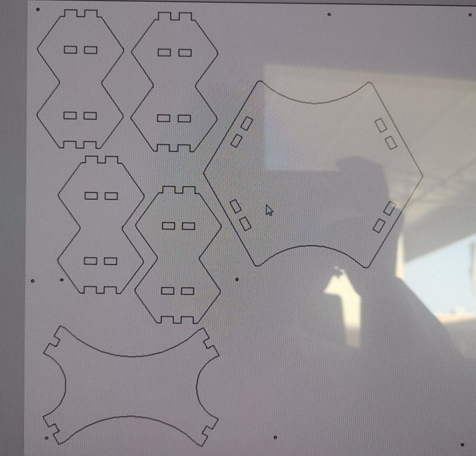
Cutting Path and 3D View
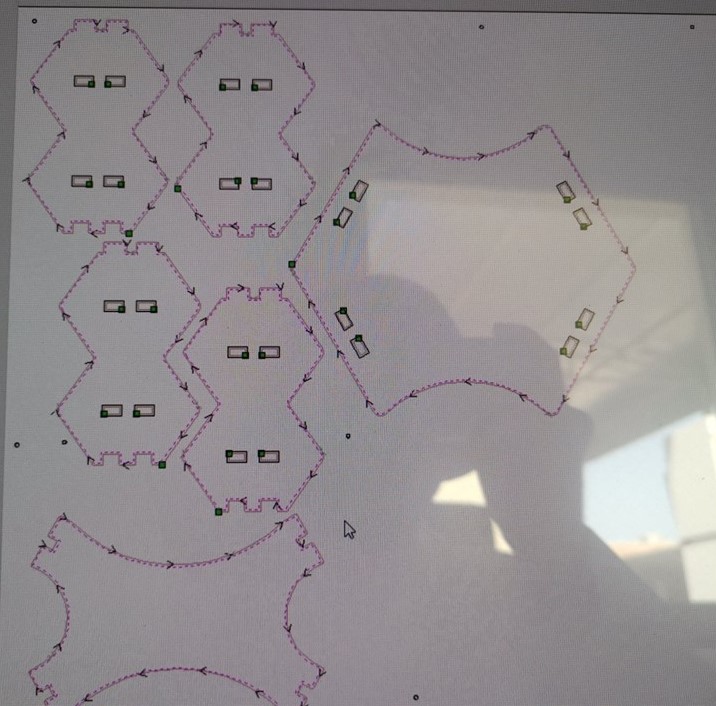
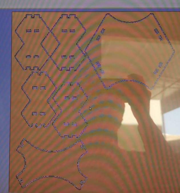
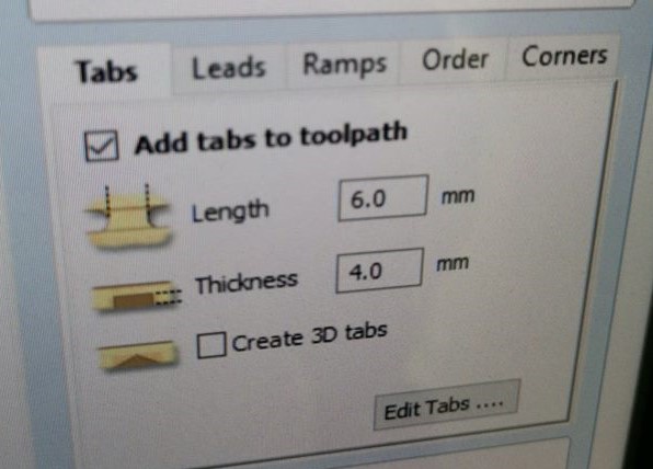
Do Not Forget To Add TABS As Well - Prevent Pieces From Flying: These tabs secure each object and prevents them from moving out of their place during the milling process.
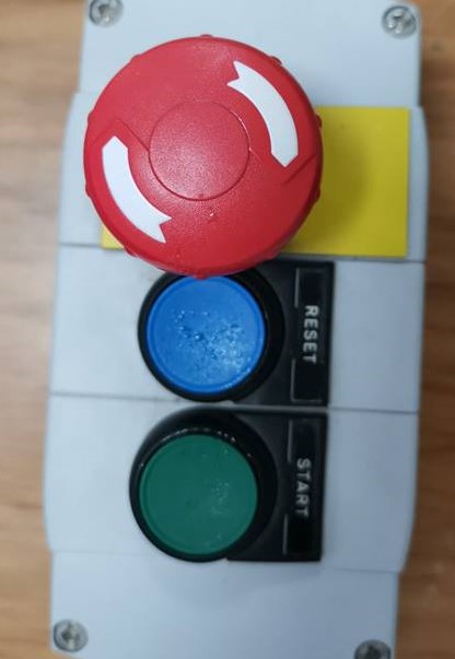
Press "Cut" and Loading Cut Path Files, then Press "Start": Each saved toolpath for drilling, cutting objects, and cutting resumed objects must then be loaded using the cut button on the red background GUI. Once the toolpath is loaded, the milling process can be started by clicking the green "START" button.
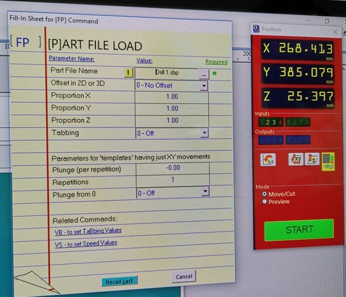
Do Not CLICK OK Before STARTING the Spindle!
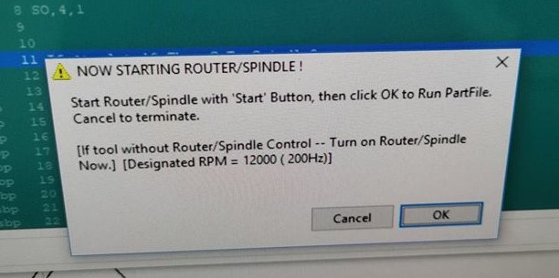
Turn ON spindle
Press "Green" Start Button
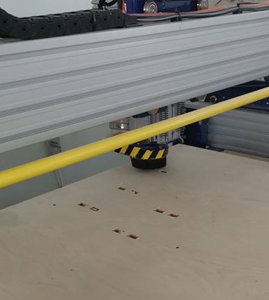
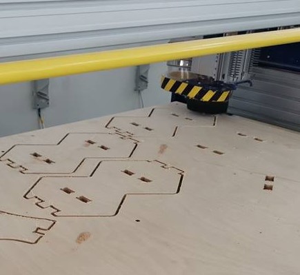
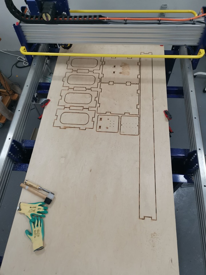
Cutting In Process
This What Happens When Vacuum Stops Working: Earlier I thought to myself, why do we need vacuum for this machine. This happened and I realized how much wood residue is sucked by the vacuum machine. It is also annoying to have the vacuum machine stop working as then the tabs are not visible.
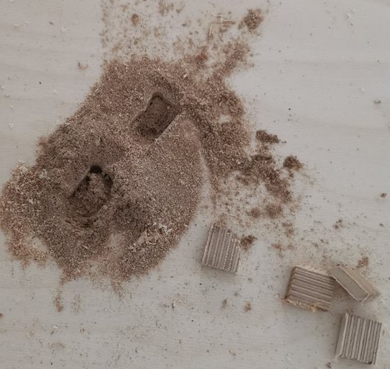
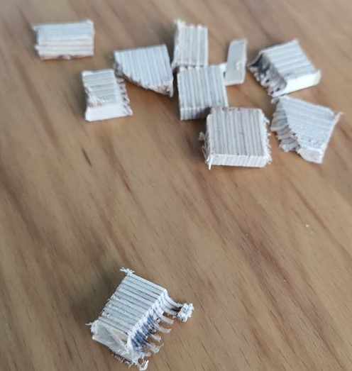
These Parts Also May Come In Contact With Spindle, Contact May Cause Fire: Since there were no tabs added for inner parts, these small parts started flying away. There is a chance that friction between these parts and the spindle can start a small fire.
Resuming Cutting Process
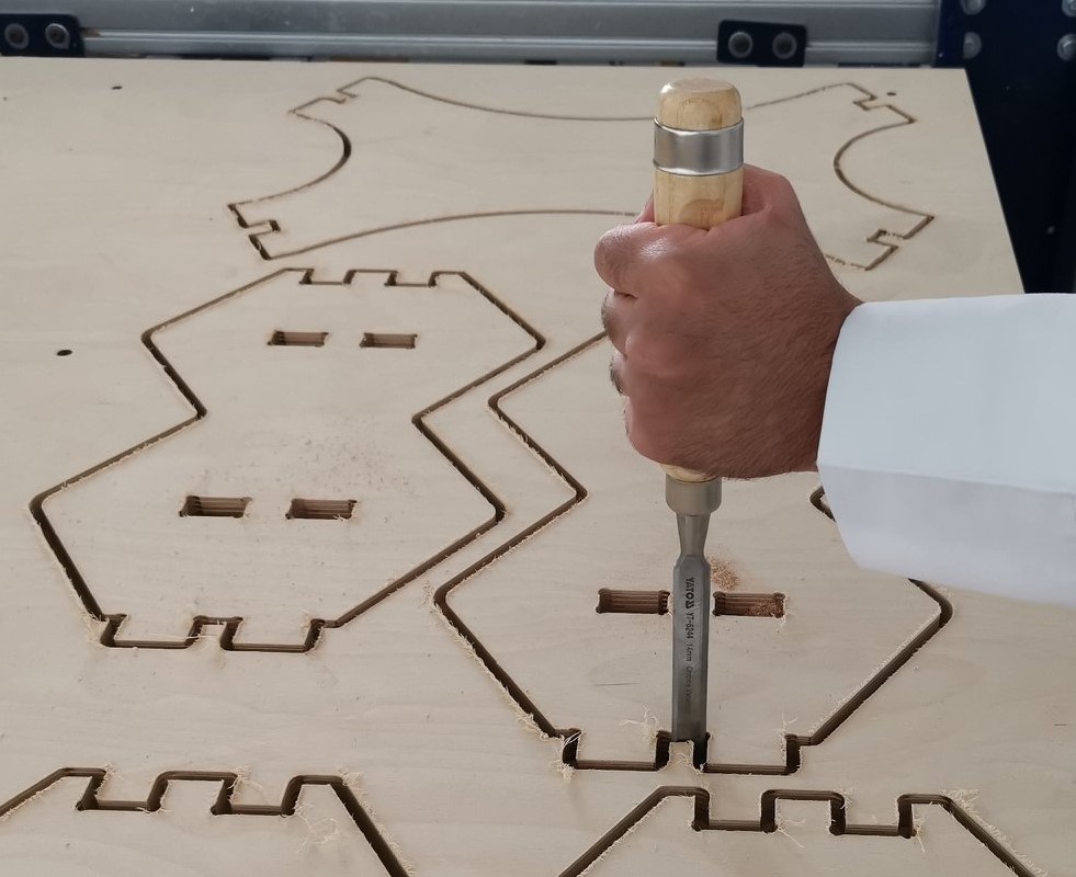
Finding 3 Tabs of Each Part
Removing 3 Tabs To Remove Each Part
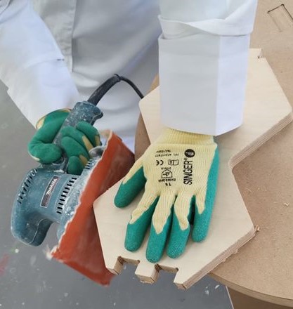
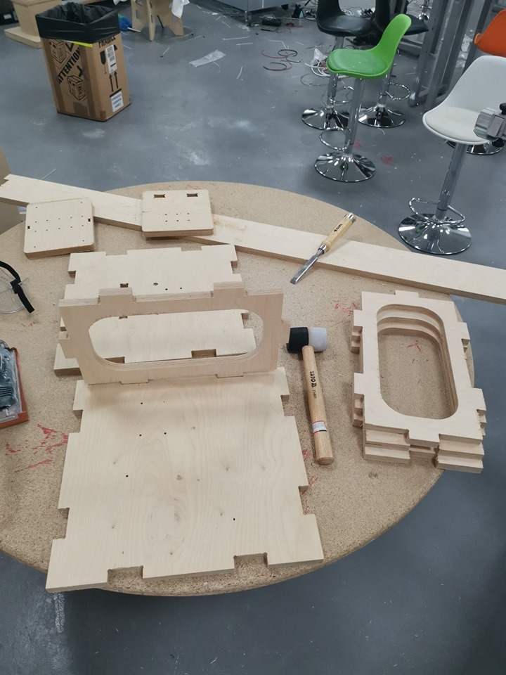
Sand Paper Tool To Smoothen Edges
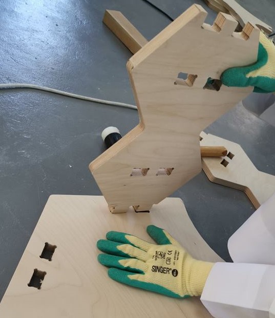
Joining Parts Using Rubber Hammer
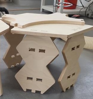
Results
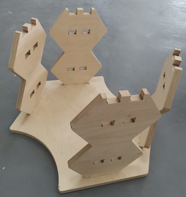
Results: The top part did not fit due to dimension error as a result of a mistake I made during the design process. In addition, the latest file was not successfully updated to Fusion360 cloud, and the progress rewinded to a previous stage in the design process. The scale and dimension of components at that point were scaled differently. I decided to stop here as the effort would be required to make the same design would be difficult at this point. An attempt to fulfill the requirements of this week will be made during the making of the final project as advised by mentors.
Project Box - Attempt 2
In this attempt, the points covered previously may not necessarily be repeated. However, information on CNC machine work flow, 2D sketch, 3D design, and feeds and speeds used will be covered in this section of the page based on the comments received from mentors.
CNC Machine Workflow
To subtractively manufacture a component using a CNC machine a 3D design of the object is required. Each component making up the 3D designed object must be projected into a 2D sketch which would then be exported to a DXF file format. The only information lost in this process is the thickness of the 3D object, all components should have the same thickness in the design, a parametric design would be useful in this case, a change of a single variable would result in adjusting components thickness according to the material available in stock while maintaining component's sketch features such as joints and etc.
The DXF file, obtained from a CAD model, would then be used or imported into a CAM program. The CAM program would be used to create different tool paths. First inner features of the components must be milled, and any joint must be filleted using a dog bone joint. The toolpaths are then saved as a post processor file which can be used directly by the CNC machine.
Project Box - 2D Sketch and 3D Design
The project box is an important component which would be used in assembling the final project platform. The box would enhouse electronics, controllers, and a power supply. The box would also have open sides, to make components visible. The box would consist of 6 components which would be joined together by press fitting. In press fitting, each teeth is expanded by 0.4 mm to compensate for the kerf.
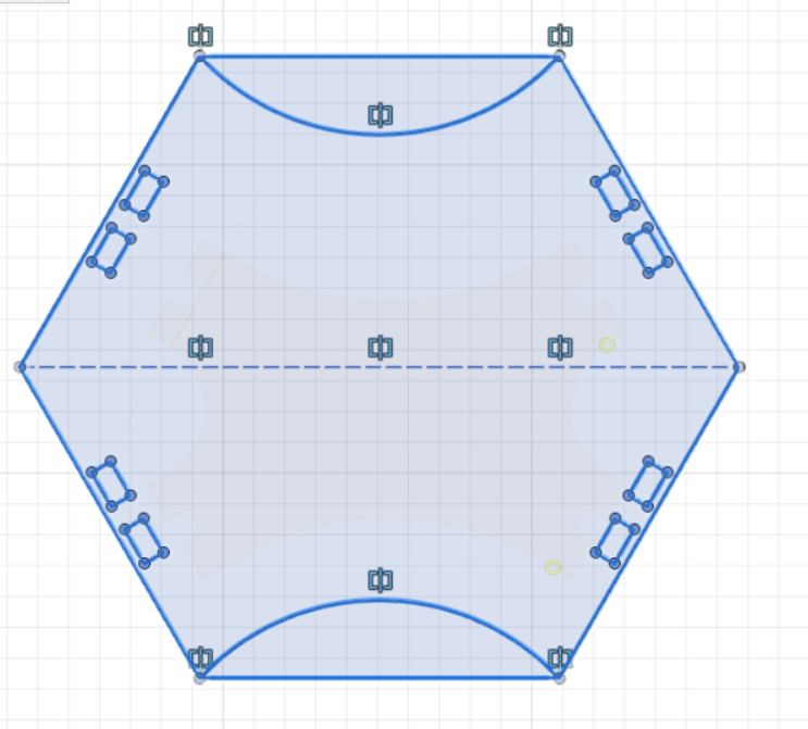
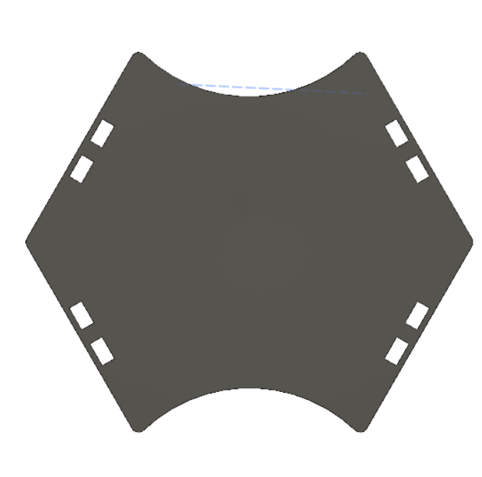
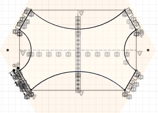
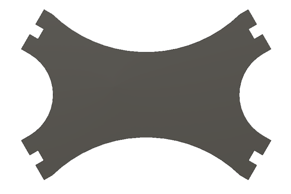
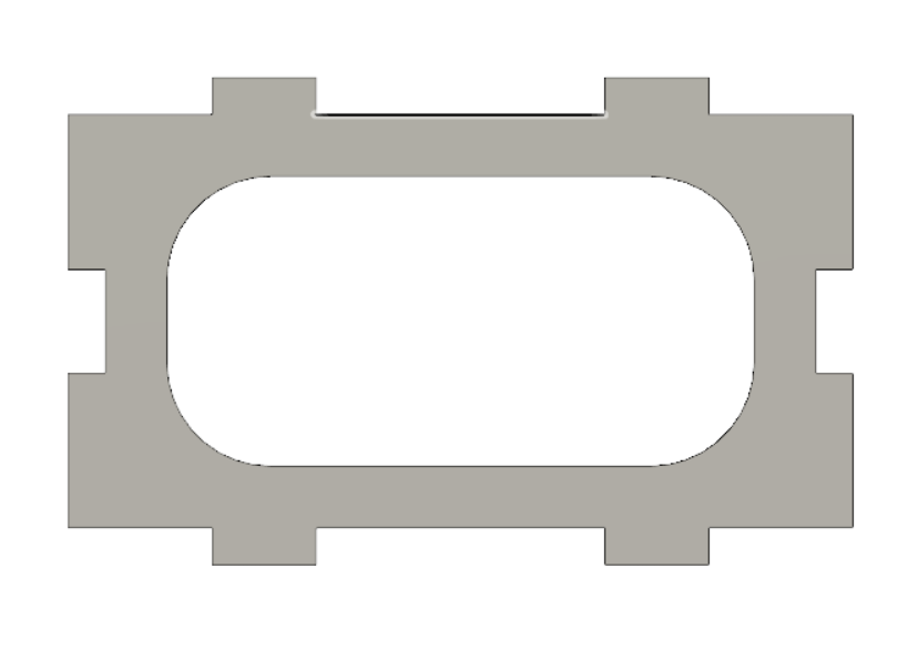
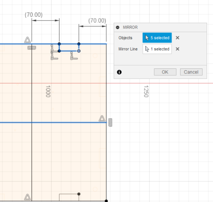
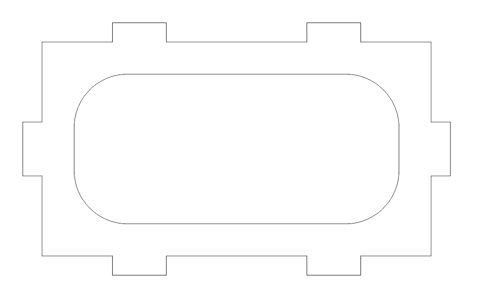
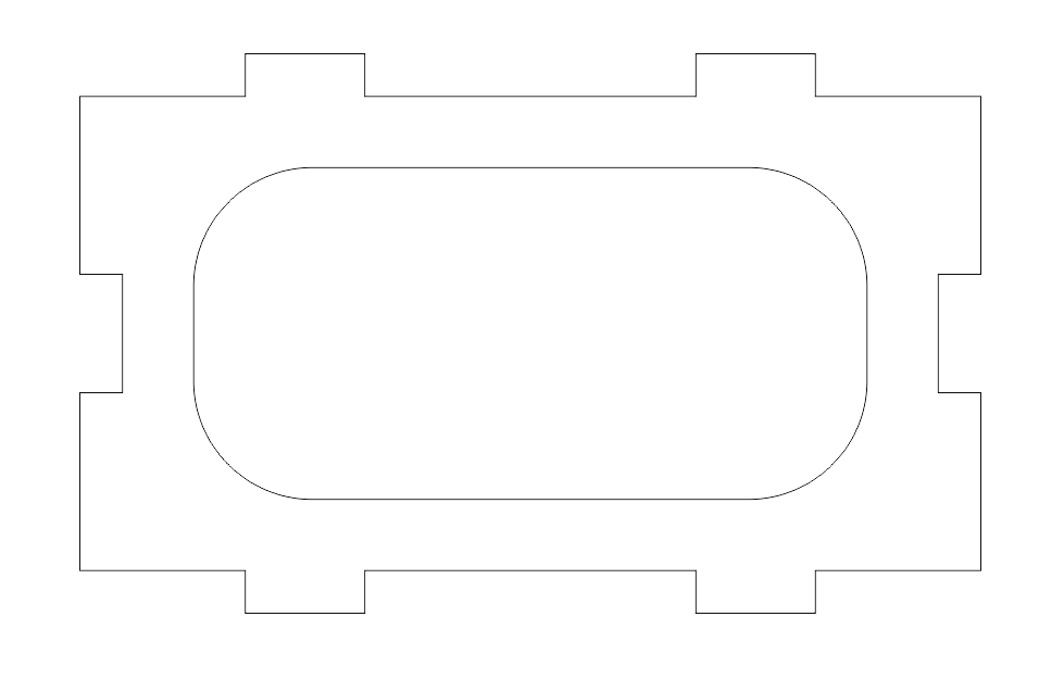
The following component is the one that would make up the sides of the box, all four of them. Opposing sides are same, adjacent sides are not. The difference is one side has teeth on its sides which are used to join the other adjacent part using press fit.
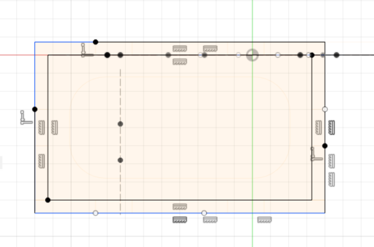
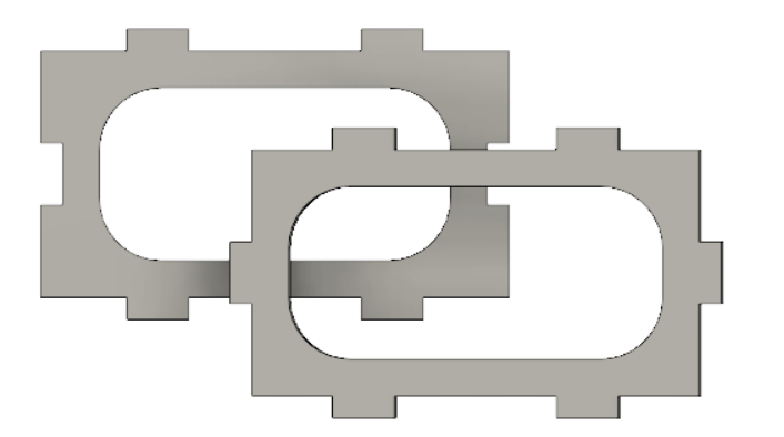
Below, the two components which would make up all four sides of the box.
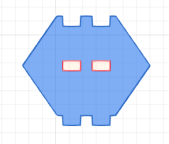
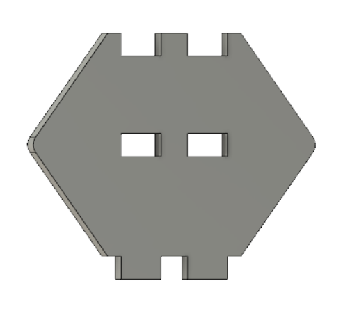
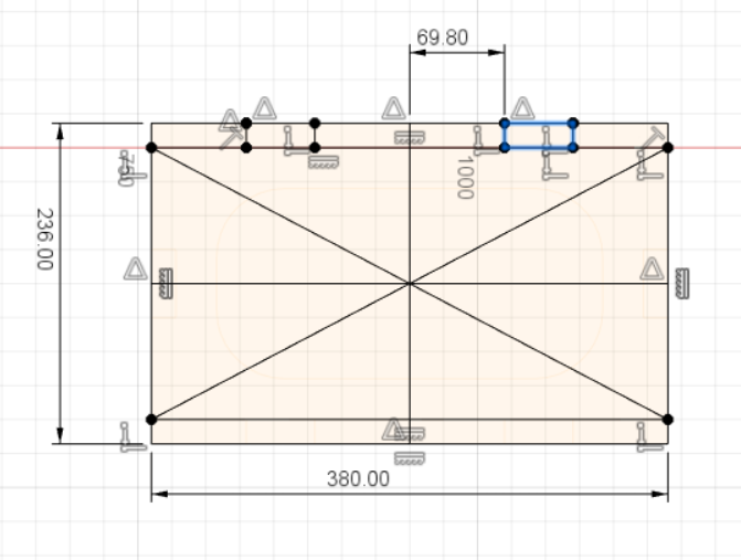
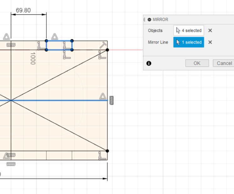
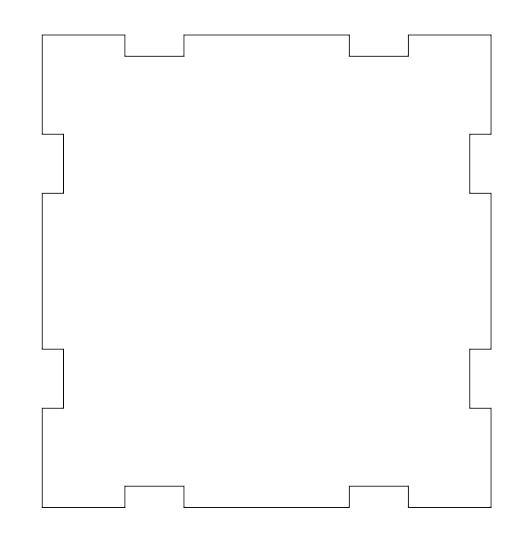
Next is the design of the top and bottom components of the box. The vertical features from side components will fit into rectangular holes of the top and bottom components. The top/bottom components are of the same sketch.
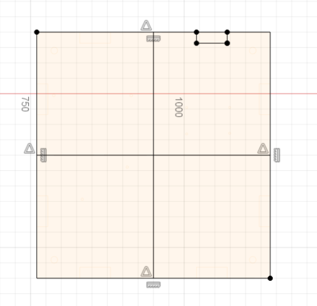
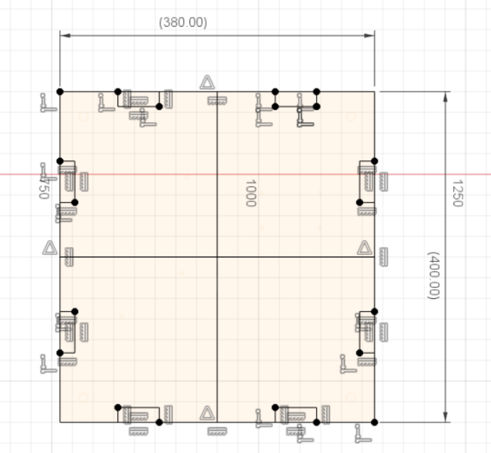
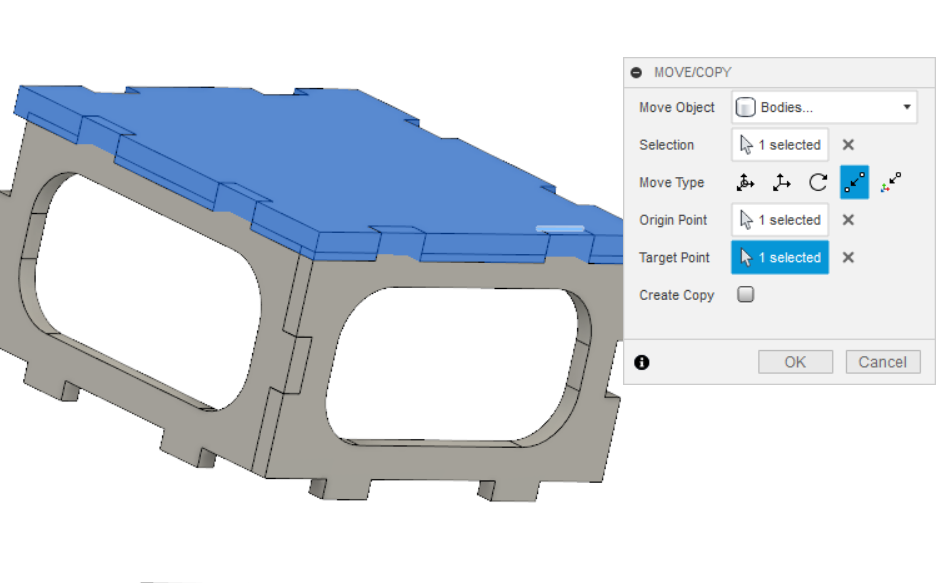
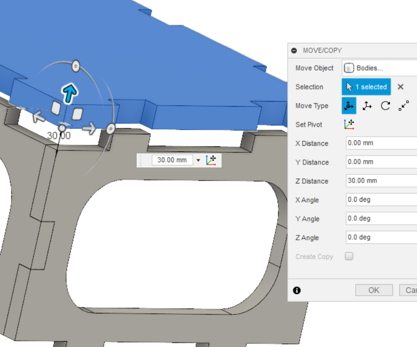
Below is the completed top/bottom component of the box. All components will now be moved to form the box. It is always important to assemble objects in Fusion360 to ensure all features of the 3D design are correct.

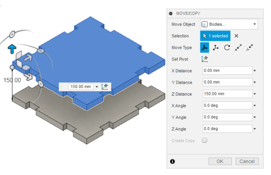
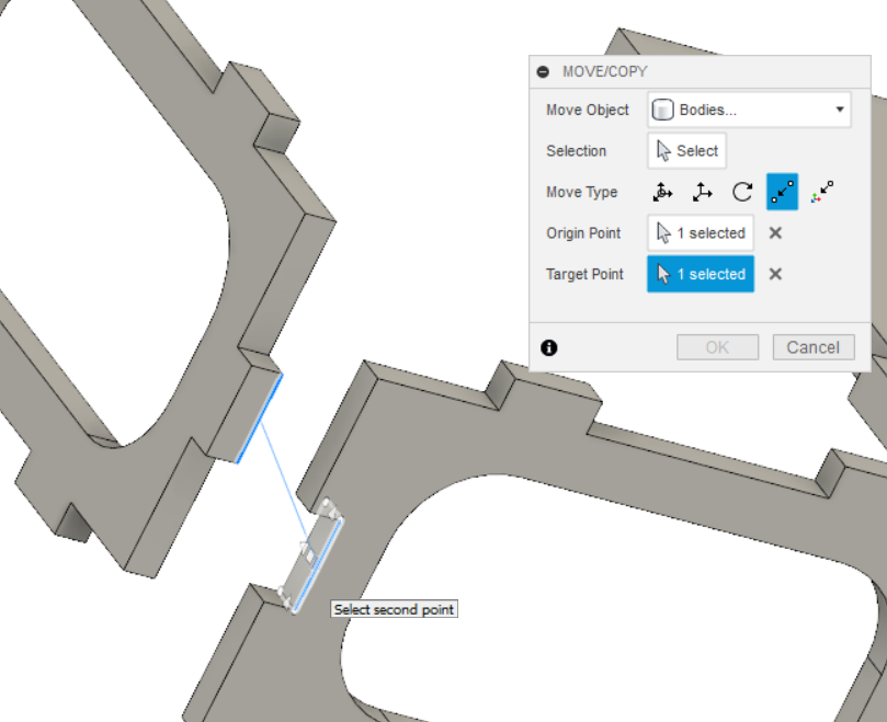
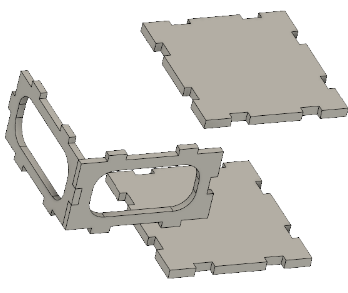
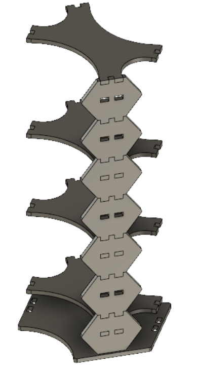
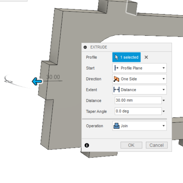
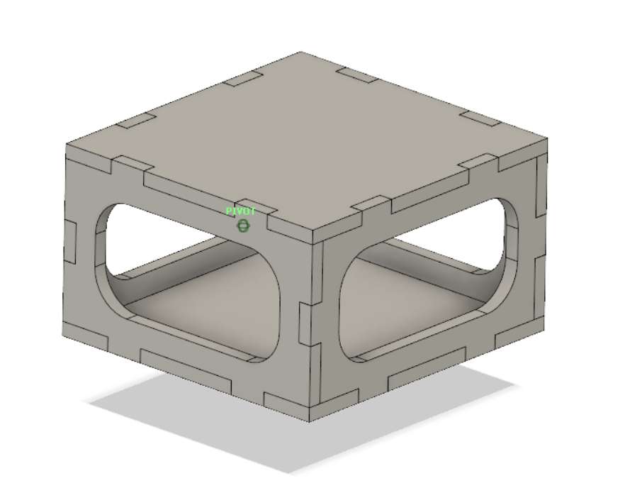
Below is the complete design of the box. The next step would be creating a projection of each side to export 2D features into sketches, which would be imported into the CAM software.
CAM Software
As mentioned earlier, in this step the previous components 2D features as exported into DXF format, three files making up all 6 parts of the box are exported to DXF format. The files are then imported to the CAM software of the CNC machine.
Steps relevant to creating tool paths and dog bone fillets, etc has been documented earlier in this page. However information on feeds and speeds will now be documented.
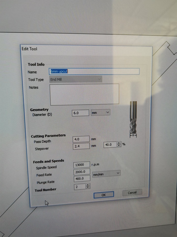
The tool diameter used for this job was 6mm. The spindle speed was around 13000 RPM, and feed rate at 2000 mm/min. It is good to note that excessive spindle speed would effect the tool, and often break it if not wearing it out. Also it should be fast enough to prevent burning the material. As for the feed rate, it is the rate at which the material is removed, a fast rate would remove the material faster but must be constrained depending on motor's power. Also, a slower feed rate would result in finer milling.
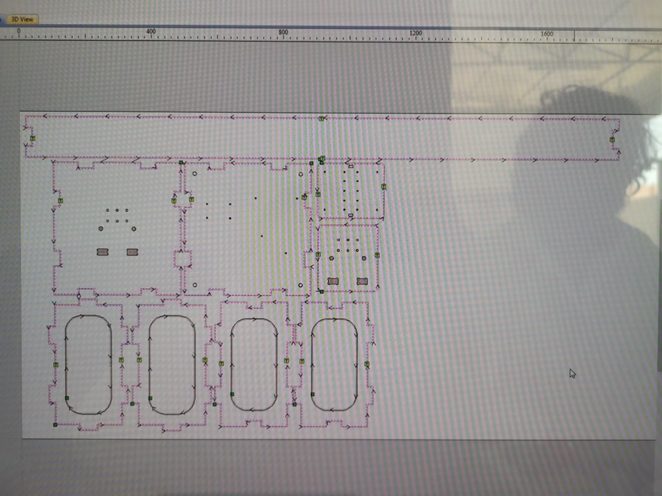
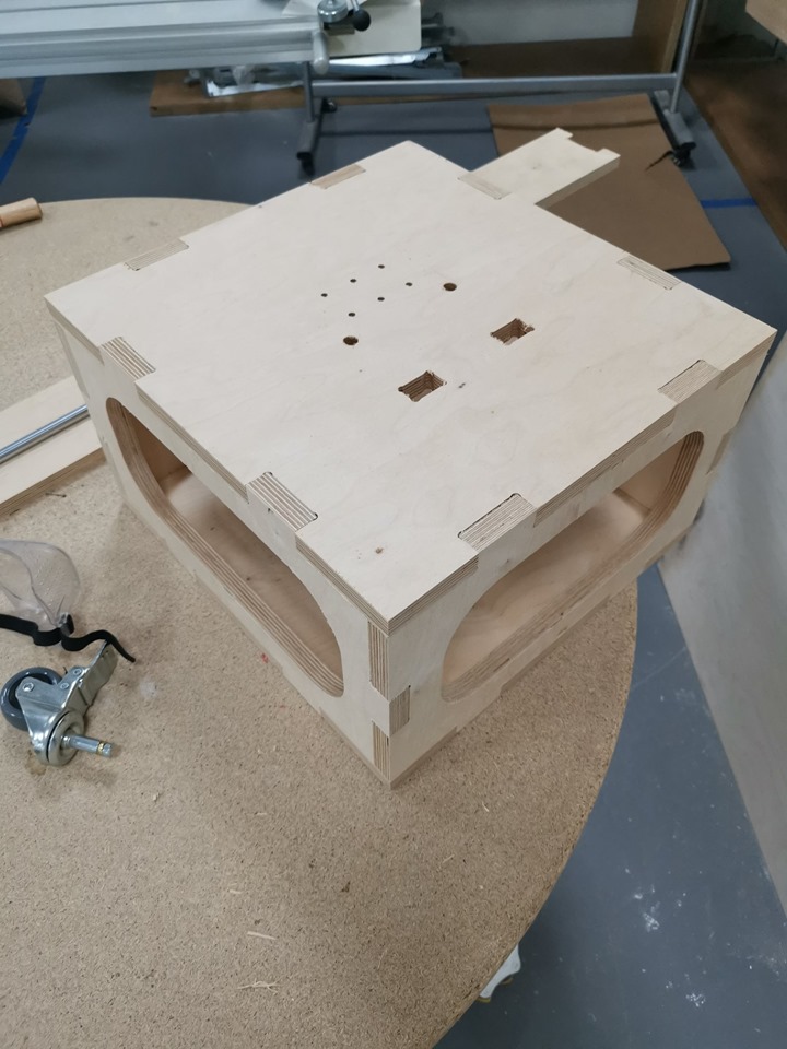
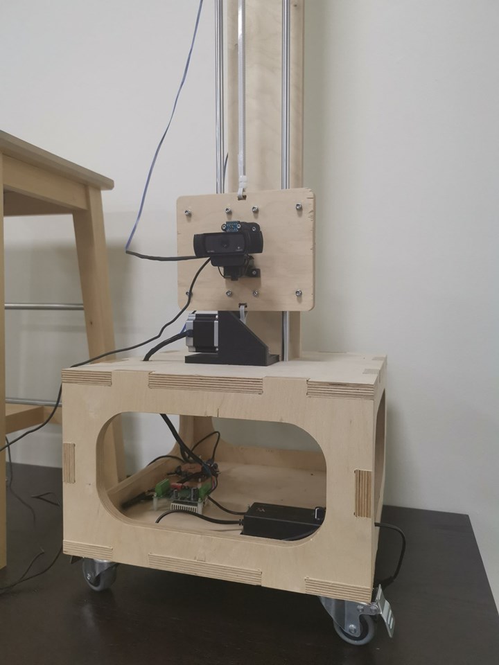
The box project depicted in the below image, as part of the final project platform.