Computer-controlled cutting
Objectives of the week
- Group assignment
- characterize your lasercutter, making test part(s) that vary cutting settings and dimensions
- Individual assignment
- Cut something on the vinylcutter
- Design, lasercut, and document a parametric press-fit construction kit, accounting for the lasercutter kerf, which can be assembled in multiple ways
I never used computer controlled cutting, so I am glad to jump in the unknown!
What I did
- Designed parametric parts on FreeCAD
- Made a drawing on inkscape
- Used interfaces for a laser cutter and a vynil cutter
- Characterized and parametrized a laser cutter
- Played with a press-fit structure
- Spread the love of bikes
What I learned
- To characterize and use a laser cutter and a vinyl cutter
- To manage file formats
- To make press-fit joints
If I had the time to go further...
- Test other press-fit joints
- Play a little bit more with my press-fit kit
- Try to develop parts of my final project with press-fit joints
- Try more complex projects on the vinyl cutter (several colours, complex shapes, other materials, ...)
- Make my city greener and greener...
Files and resources
- The source files for the press-fit can be downloaded here
- The source files to spread love of bike can be downloaded here
Step 1 (laser): group assignment
What we have done
We deploy three tests:
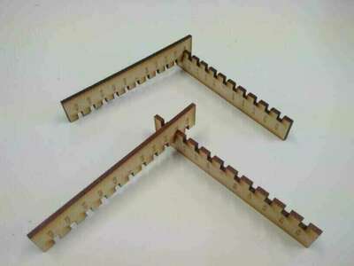
- Press fit, using two combs with different teeth width (Process 1)
- Power and speed parameters, using color mapping to cut rectangles at different settings values (Process 2)
- Kerf width on a straight rectangle of known length cut in 10 equal pieces (Process 3)
Resources available @Fablab ULB:
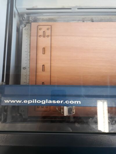
- The laser cutting machine is a CO2 60W EPILOG MINI, with a useful surface of 30x60 cm, interfaced with CorelDraw
- Available material for the test is a 3mm MDF wood plate.
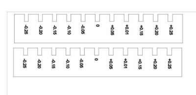
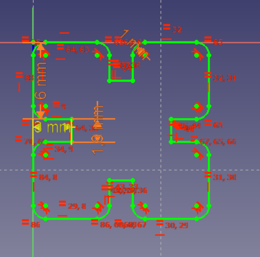
Process 1:
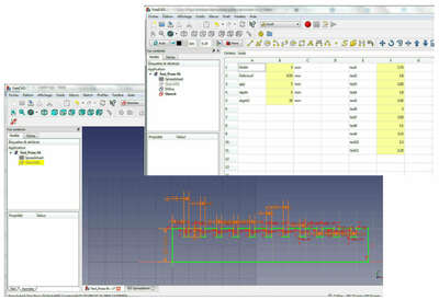
A parametrized comb structure is defined in the FreeCAD Sketcher module, using a parametrization based on the width plate as basic parameter (all parameters defined in Spreadsheet)
- Plate width: 3mm (alias: width)
- 11 variable slots sizes varying from with-0.25mm to width+0.25mm, by step of 0.05mm (aliases: test1 to test 11 variables)
- depth of the teeth: 5mm
- overall depth of comb : 20mm
- distance between teeth (gap): 7mm
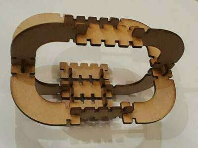
Here is the result:
In a second stage, the file is exported to DXF format (File > Export > Autodesk DXF 2D ) to be read by CoralDraw, the softawre used to communicate with the laser cutter. Note that the preference Allow FreeCAD to automatically download and update the DXF libraries must be turned on in FreeCAD.
In CoralDraw: * The width of each slot is added as text, to be engraved on the MDF plate. Do not forget to convert text to curve, and to change the text thickness to 0.2mm to make it more readable.
- Lines to be cut need to be defined as “ligne très fine” (very thin lines)
- Lines to be engraved do have a defined thickness
- When file is ready to be sent to printer, define the settings in the EPILOG driver in CorelDraw:
The standard settings for wood are given below (extract from EPILOG manual):
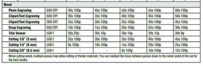
For a 60W machine:
- Text Engraving: raster, 600DPI, speed: 45, power 100
- Cutting 3mm: vector,pulse frequency: 500, speed 40, power 100
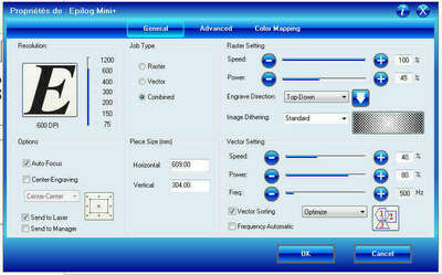
As both engraving and cutting are used, do not forget to check the option combined!
Printer setup :
- Place the MDF wood plate on the honeycomb support in the printer
- Caution: take care to start the design by defining the origin point through manual settings if needed ( On Epilog mini dashboard: set manually zero position (pointeur > x/y off > (move manually the laser pointer) > définir origine))
- Do not forget to start the gas extractor and its pump, altogether with the laser printer itself!
- Press Go on the dashboard when Job, sent from the controlling PC, can be started…
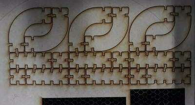
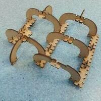
We’ve tried three sets of tests:
- First test (top left): Power 80, speed 40 : comb is not completely cut (power too low)
- Second test (top right): Power 100, speed 20: comb is completely cut but wood is burnt (speed to slow)
- Third test (bottom): Power 100, speed 40 (standard settings): comb is cut and wood is in better state!!! Definitely the best choice!
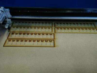
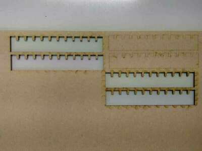
Concerning the best press fit, we see that for the second test, it is the slot -0.25mm, whereas for the third test, the best fit is -0.20mm. In this latest case, we can then estimate the kerf width to 0.10mm.
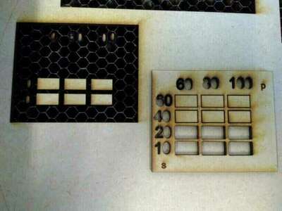
Process 2
In this test, a simple structure of a 4x3 rectangles is directly drawn in CoralDraw, with power (p) and speed (s) as parameters of the color mapping
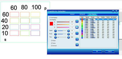
The result is that for speeds 10 and 20, all rectangles are really cut, for speed 60, no rectangle is cut. For speed 40, only the rectangle cut @ 100 is cut (standard settings!!)
Difficulties encountered : there has been a superposition of rectangular frame at creation that lead to two passes of the laser! Failed! The combination of raster, vector and color mappings is more difficult than expected, and forms that were meant to be engraved were finally cut ( the numbers, colored in black, not used in color mapping were thicker than expected!!). Be carefull in this case!
Process 3
In this test, a rectangle of 100mm is drawn in Coreldraw, and then cut in 10 equal pieces.
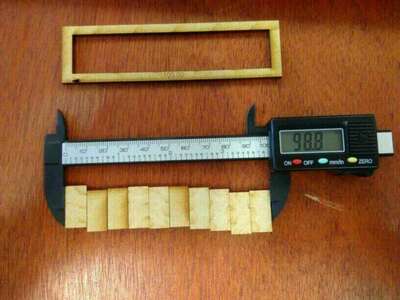
Measuring the remaining width (98.8mm) on small rectangles after cut,kerf may be estimated to: width(1.2mm) divided by 11 : 0.11mm
This latest test didn’t bring any specific difficulty.
Job done!
Summary
Optimal parameters for 3mm MDF wood plate cutted with a CO2 60W EPILOG MINI
| Parameter | value |
|---|---|
| Cut power | 100 % |
| Cut speed | 40 % |
| Cut frequency | 500 Hz |
| Engraving power | 100 % |
| Engraving speed | 45 % |
| Engraving quality | 600 DPI |
| Kerf width | 0.11 mm |
| Optimal fit | 3 - 0.20 mm |
Step 2 (laser): Parametric design
To continue on the laser cutter, let’s design my press-fit kit!
I’ll do my parametric on FreeCAD, to continue in the same software that I started on week 3. Based on the results of the group assignment, here are the parameter I defined in my spreadsheet:
| Parameter | Value | Alias |
|---|---|---|
| Thickness | 3 | th |
| Fit adjustment | 0.2 | fit |
| Cut depth | =1.5*th | depth |
| Fillet (radius) | =th/2 | cong |
| Cut width | =th-fit | width |
| Cut gap | =2*depth | gap |
| Curvature radius | =2*gap | curv |
All the design parameters depends only on the thickness and the fit adjustment of the pieces.
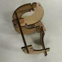
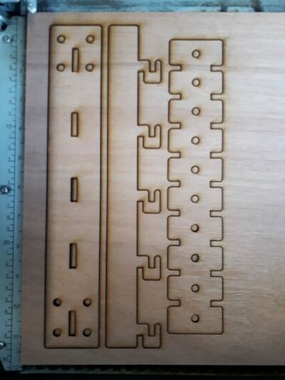
Three different parts are designed, my preferred one being the curved one, which allows to create fancy assembly in the space and larger and “smoother” geometries. I use fillet to ease the assembly of the pieces and to make them smoother.


Difficulties: I can still improve in the way I organise my files in FreeCAD. I tried to use subfolders but when using different workbench I didn’t manage to respect those subfolders. I also had trouble with FreeCAD lagging and closing when I want to use specific functions or when my drawings become to complex.
Step 3 (laser): Let’s cut!
Now that I have my pieces, let’s cut them using the optimal parameters tested in the group assignment.
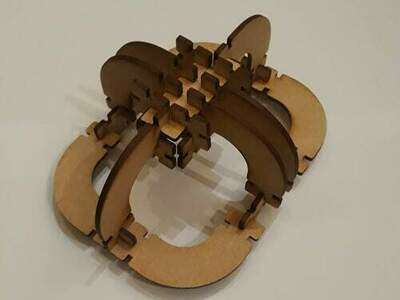
It worked directly, and I can try some assemblies.
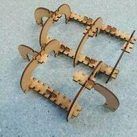
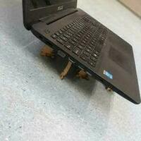
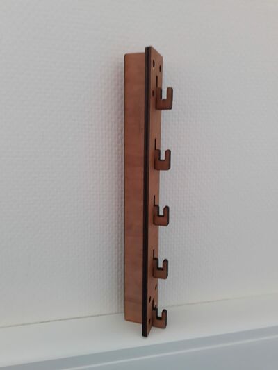
It’s even better that I expected! The press-fit is perfectly adjusted, the curved pieces allows many possibilities, and the MDF wood gives rigidity to the structure. I can use it to ensure my laptop to stay cool! Let’s make some more assemblies:
The source files can be downloaded here
Step 4 (vinyl): Designing what I’ll cut
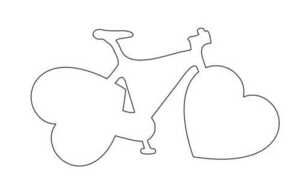
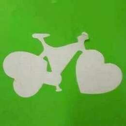
For this part, I’ll use inkscape for vector drawings. I want to make stickers for my bike… or for traffic lights. Since biking is loving, I call this little project bike-love.
The process is documented in the captures below:
- First thing: find some images.
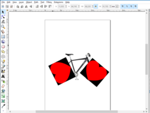
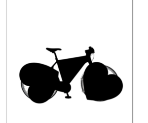
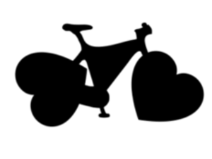
- You already understand what I have in mind. The second step is to vectorize them on Inkscape (tuto).
- I must then clean the image by removing internal paths and simplifying external ones. I am just a little bit worried to have too thin parts.. Spoiler alert: everything got perfect! To combine my three objects (the two love symbols and the bike), I use a Boolean union (
path --> unionmenu). - Last step: convert the shape to paths, make last small corrections and… Tadaaa! I have my bike-love.
Step 5 (vinyl): Let’s cut… Again!
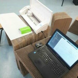
The available vinyl cutter is a silhouette Cameo. Some French user guides can be found here and some French tutos here. The principle is very simple: make a vector drawing and send it to the vinyl cutter as I you printed it.
To communicate with the Cameo, I have two options:
- Using an inkscape add-on. This solution seems great and really elegant and convenient, but it unfortunately did not work on my computer (it did not suceed to communicate through the usb port). I suspect this problem to be related with the Linux installation I made last week, as Adrien documented it.
- Using Silhouette studio, the cutter software. I finally resolved to use this second option.
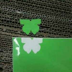
I tested first the vinyl cutter using a simple butterfly design found in the Silhouette studio library.
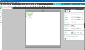
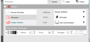
The interface is basic and to print start the cutter, I just have to press on the sned button. There is very few parameters to set, to most important one being to configure which material will be cut (in my case vinyl brillant - glossy vinyl). The blade setting is automatic based on the material.
The “hardware” installation is not much more complicated. We need first a sticky support (with the grid). When the protective transparent film is removed, the vinyl to be cut (and its protective layer) can be placed on the sticky support. The grid corresponds to the interface of Silhouette studio. The sticky support and the vinyl can be loaded in the cutter (there is only one button). Be sure that your computer is connected to the cutter, and let’s go!
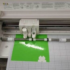
It worked, but the vinyl was misplaced when loaded, so all the calibration was shifted, and the support was a little bit damaged outside the cutting zone.. be careful when loading!!
Now that I can run the cutter, let’s make my sticker!
I had som difficulties to import my drawing on Silhouette studio. The free version does not accepts .svg files, so I had to export it from inkscape under .dxf format. After many tries, I finally managed to export the file correctly using the ROBOT-master exporter for .dxf.
Using the same settings that for the butterfly, here is the sticker I obtain:
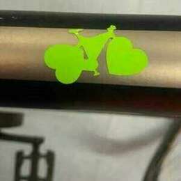

I put one on my bike, and the others to spread bikes in love in Brussels!
The source files can be downloaded here
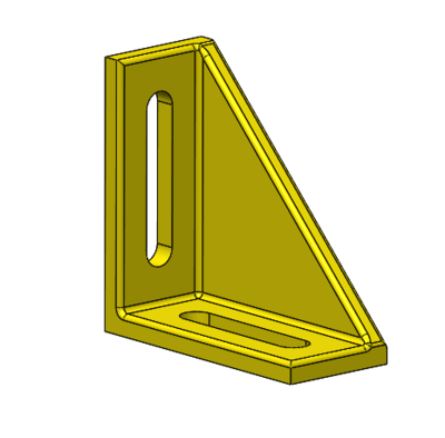
Update weeks 8 and 12: Designing and cutting the structure of my final project
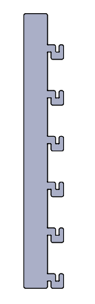
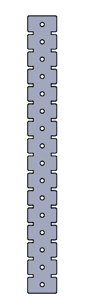
The week 8 was about making something big with the CNC. My first idea was to make the structure that I already designed a little bit in week 3. However, this is not really “big” and this would be more suitable to make with the laser cutter, so I worked a little bit on the structure, but aside of the assignment. I liked the simple and modular structure that I proposed in week 3, but the extruded profiles cannot be made (of course) in a fab lab. So, I tried to design an alternative. I replaced the profiles by 3 types of pieces, 2 vertical and 1 horizontal. This is not a “clean” design, but this is supposed to be as modular as possible. I tried first with FreeCAD, using multiple files sharing a “master spreadshet”, but the too many bugs and the often closing software convinced me to let it go and use Solidworks, a tool that I master. Note that I also tried Fusion 360 this week, and it was not really a success neither. I also re-designed the “home-made” optical board inspired by Denis, my instructor, that I developed a little bit in week 3. Of course, I made all the design perfectly parametric.
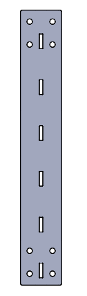
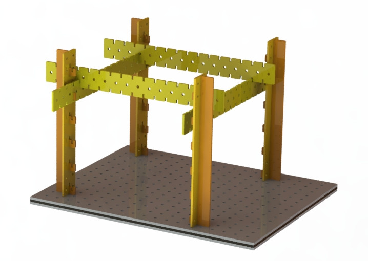
I made several tests to find good settings. I used left-overs of multiplex having a thickness of 5 mm. They were a little bit bent, but the aim here is mainly to test the structure.
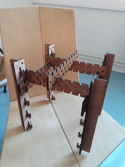
Good! This solution seems OK! I am not totally satisfied since I feel like the structure could be simpler, but this design is rigid enough for the moment, and is very modular! As a backup commercial plan, I still have the possibility to use aluminium profiles.
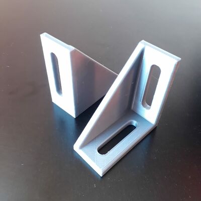
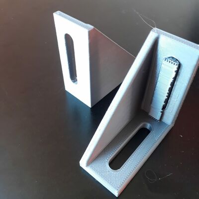
However, I still need fixations to fix the structure on optical breadboards. Here is the designed fixation, printed in 3D. I tried in parallel to print it with and without support, and the result was very similar, let’s avoid to waste material into supports!