Electronics production
Objectives of the week
- Group assignment
- Characterize the design rules for your PCB production process
- Individual assignment
- Make an in-circuit programmer by milling the PCB, program it, then optionally try other PCB processes
I am not a complete stranger to electronics and PCB production, but I never made it myself, so I am looking forward to understand better the process.
What I did
- Discovered and used the PCB milling machine
- Welded my fabISP board using a ATtiny45
- Spend a lot of time to debug and finally program my programmer
What I learned
- To use the CNC milling machine
- To weld tiny tiny components
- That Linux is cool
If I had the time to go further...
- Testing other ways to make PCBs (on the vynilcutter!)
- Trying to (really) understand what I did to program my programmer
Files and resources
- Here is the final svg file that worked.
- ATtiny45 Traces
- ATtiny45 Outline
Step 1 (group assignment): characterizing the machine
Material and setup
We use the following PCB milling machine Bantam. The first thing is to install driver available here.
Traces width characterization
Getting an svg image
We use the pgn file provided by Neil. The software only accepts images in svg, so let’s play with image format!
- Test 1 (failed): using only Inkscape: Using only inkscape, the first step is to use the function trace bitmap to vectorize the image. The image can then be exported as svg. Problem: The image scale is lost between inkscape and the Bantam software.
- Test 2 (failed): reducing the image resolution with GIMP: Since the image has an extreme resolution (5000 ppp), we first reduce its resolution to 1200 ppp before vectorizing it on inkscape. Problem: The image scale is still different in every software.
- Test 3 (succeeded): Using a commercial Software We solved the problem using CorelDraw (bye bye open source…). The same process is used:
- Reduce the image resolution to 1200 ppp
- Vectorize the images (trace the bitmap). Be careful to remove the background, i.e. to have only one colour (black) which indicates the zone to be milled. Note that we also tried with Illustrator but it did not work. The problem is probably that the background was not remover for this test.
Here is the final svg file that worked.
Preparing the PCB milling machine
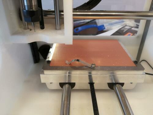
Placing the PCB
The PCB plate must first be placed in the machine. One important thing: fill the bottom side of the PCB with double-sided adhesive before to place it in the machine. This will allow the PCB to be fixed.
Calibrating the machine
There are nice wizards for the calibration:
- Homing: just follow the wizards
- Locate tool (measure its size): It will use an electrical contact to know when there is contact. You must make sure that the tool is placed above the metallic part of the plate, so that the electrical contact is good.
- Height of the PCB: This wizard is a little be hidden (
bitbreaker->probe material). It uses the same principle, but this time on the PCB. You have to make an electrical contact between the PCB and the plate using the little “jumper”. In this case, the height of material was recalibrated to 1.69 mm.
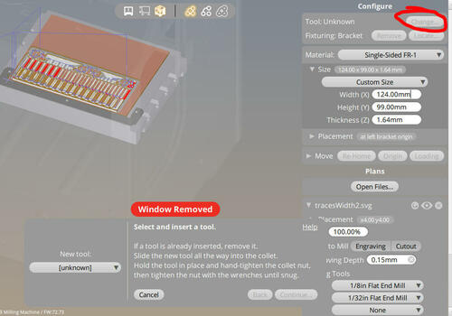
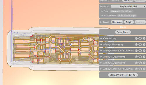
Configuring the Bantam software
The software has quite a nice interface. You just have to follow the process.
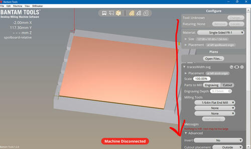
Machine parameter
Here are the parameters use for the support and the machine.
| parameter | Value |
|---|---|
| Material | Single-sided |
| Size | 124.00 mm x 99.00 mm x 1.64 mm |
The move options allow to move the plate. You can bring it close to the opening using the loading button.
Job parameters
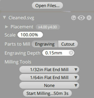
You can then import your svg file. The parameters are quite straightforward.
You can chose up to tree mill to be used for one job. The machine will use them from the smaller to the larger, and you will need to change it during the job. You can change the parameters for each mill by adding custom tools in the tools menu (files->tools).
Here are the default milling parameter used by Bantam. Note that the speed and the pass depth can easily be increased to make it faster. More information can be found here
| Parameter | Value |
|---|---|
| Feed rate | 300 mm/min |
| Plunge rate | 30 mm/min |
| Spindle speed | 30000 rpm |
| Stepover | 15% |
| pass depth | 0.1 mm |
We decided to do it in three steps to force the machine to use first the middle-sized tool. Be careful for the placement, every drawing must be perfectly superposed! Note taht we also tried with the default settings (i.e. from the thinner to the larger mill), and it gave the same result.
| Step 1 | Step 2 | Step 3 |
|---|---|---|
| 1/32in mill | 1/64in mill | 1/8 in mill |
 |
 |
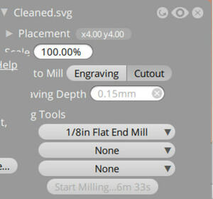 |
| Rough engraving | Thin engraving | Cutout |
| Full job | Cancel when you should change the tool | full job |
You have to remove the waste (by vacuum) and change tools between each step.
Launching the job
- Changing the tool: You first have to tell the machine you will make the change. Then, simply unlock the tool and place the new one using two wrenches. Be careful that the mill cannot fall, it could break!. The wizard will then automatically calibrate the tool height, you just have to make sure that the tool is placed above the metallic part of the plate.
- Let’s go: just press on the “Mill” button, and it starts!
| After step 1 | After step 2 | After step 3 |
|---|---|---|
 |
 |
 |
During the milling, you’ll have a lot of waste…, but a nice interface showing real-time the position of the mill.


Removing the PCBs
- Remove all the waste.
- Remove the prepared PCB. Use the loading button to bring the plate close. Leave the rest of the PCB in place, it will avoid you to redo all the calibration. You can use a screwdriver to remove it easily. Note: keep also the software on and do not remove the previous projects, it will allow to know which part of the PCB has already been used.
- Wash the PCB. Water and soap is good.
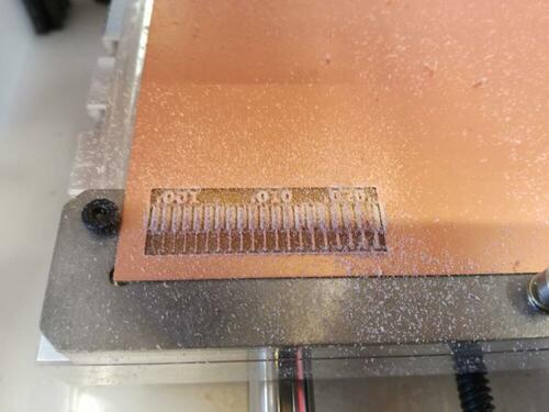
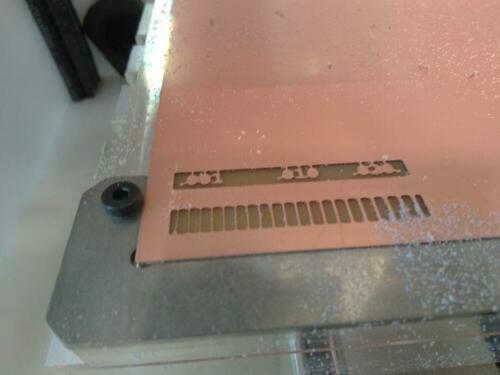
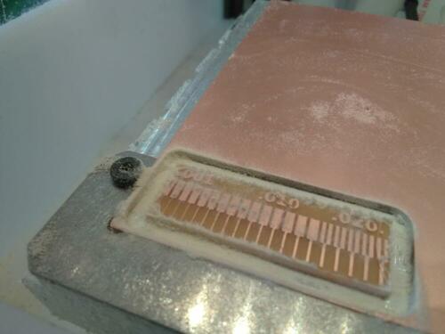
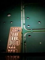
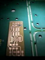
And here is the final result:
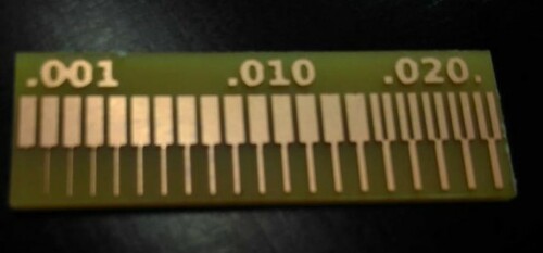
The result is good! It took however a lot of time. Only the thinnest line is gone, and the limit between two lines is around 0.15in.
Step 2: milling the PCBs
As I am quite new for this, I will follow Brian’s tutorial. This also what my instructor Denis did.
PNG files
Converted svg files
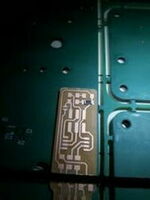
We made together the milling of the PCB’s to keep the rhythm of the group assignment, and followed basically the same process. We first made a test on the vynilcutter to validate the scale of the trace and check that we have all the components. We can then launch the milling of the first PCB! We do the trace in two steps: with the 1/32in and the 1/64in mills. Since we have the trace and the outline in two png files, we have to do it in two steps with the milling machine. We use a 1/8in mill for the cutout.
Problem: I did not take care and placed the two svg converted images (trace and outline) with the same (x,y) position. Of course, in the process of converting the png to svg*, I changed the reference of the images superposition
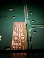
Solution: We had to manually adjust the position of the outline relatively to the traces. Here are the final shift values:
- x : 1.25 mm
- y : 1.00 mm
This seems good, let’s weld!
Step 3: Welding the components
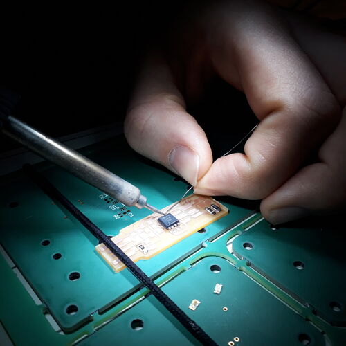
Fortunately, I had the help of Geoffrey, who works in my lab, to weld the component. He has a nice setup to weld and an amazing magnifying glass.

I first made some test on old (and difficult!) PCBs. Welding the fabISP felt sooo easy afterwards! I still follows Brian’s tutorial.
Some advices and notes on the welding:
- Temperature: 400°C
- Be stable! lay your hands on the table/support
- Fix your PCB! I personally used my hair elastic to fix it on the support.
- Find your own way. There is not one way to weld. Test and find your favourite tweezers, the best orientation of the PCB, …
- You can (almost) always correct your mistakes, don’t be scary!
- Be sure to touch the traces and the component.
- Chose carefully the order for placing the components! Typically, put the large headers last!
- Axel made a nice documentation, including how to find the orientation of a LED.
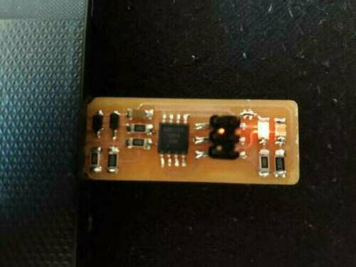
Welding the first component:
And the rest…
My final PCB:
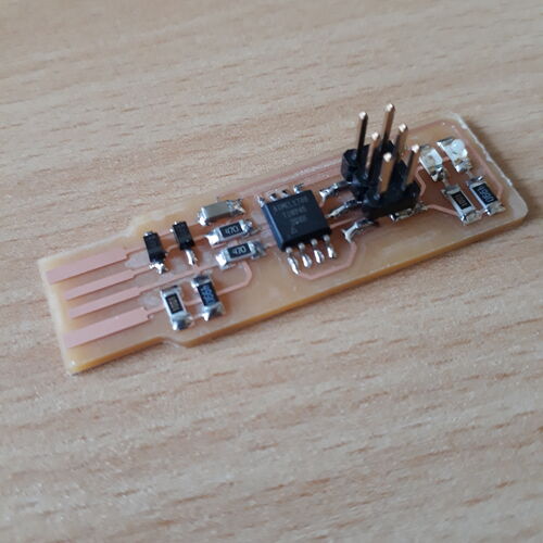
I can now test my board! The fabISP is not programmed yet, but I can put in in the USB port of my computer… The led lights on!
Two notes however:
- The PCB is too thin and does not have a good contact, I have to make it thicker by adding a layer of thick adhesive on it.
Step 4: Programming the ATtiny45
Still following Brian’s tutorial.
Installing the Software
I installed linux in week 2, so I use the following commands in bash
sudo apt install avrdude gcc-avr avr-libc makeBuilding the firmware
I downloaded and extracted the source code that can be found on Brian’s page.
I then use the command make in my bash terminal.

A new file fts_firmware.hex is created in the folder.
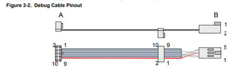
Programming the chip: test 1 - Atmel programmer
I try first to use an Atmel ICE AVR programmer. I Checked the datasheet for pinout!
I also change the makefile modifying the following line:
PROGRAMMER ?= atmelice_ispBut when I connect everything, the led does not light on..
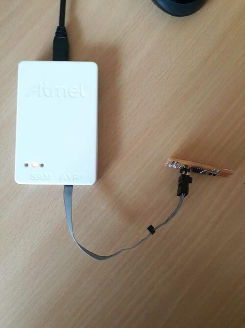
And if I check with the millimetre the output of the AVR programmer I don’t have 5V (but only 0.79V). I test however to flash the board, but got an error message:
re_bdm_v1$ make flash
avrdude -p attiny45 -c atmelice_isp -P usb -e \
        -U flash:w:fts_firmware.hex
avrdude: jtag3_open_common(): Did not find any device matching VID 0x03eb and PID list: 0x2141

avrdude done.  Thank you.

Makefile:61: recipe for target 'flash' failed
make: *** [flash] Error 1
Problem: I’m trying to program it using my linux bash but the linux kernel has no access to the hardware of my windows computer, including the usb port…
Programming the chip: test 2 - Arduino
For the second try, I followed this tutorial and this tutorial. Now the led lights on, I have (at least) the 5V
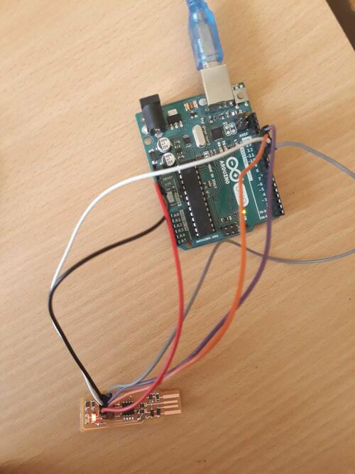
But I ran out of time and debugging seemed complicated… Let’s try (still) another solution!
Programming the chip: test 3 - fabISP and Windows
I did this part together with Christophe. We followed what Axel did:
- Download WinAVR https://sourceforge.net/projects/winavr/ and install it
- Go in the firmware folder previously unzipped.
- Edit the Makefile:
PROGRAMMER ?= usbtiny
AVRDUDE = avrdude -c usbtiny $(DEVICE)- In the Windows command:
make cleanremoves all autogenerated files.
Error message:
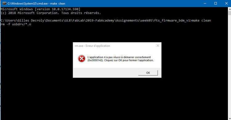
Test of debugging 1: going admin in windows: same problem..
Test of debugging 2: make clean use the rm comand which is taboo in windows. Let’s remove the .hex and .o files manually
makebuilds the .hex file.
It worked! Here is the message:
avr-gcc -mmcu=attiny45 -Wall -DF_CPU=16500000UL -I. -funsigned-char -funsigned-bitfields -fpack-struct -fshort-enums -Os -Iusbdrv -c main.c -o main.o
avr-gcc -mmcu=attiny45 -o fts_firmware.elf main.o usbdrv/usbdrv.o usbdrv/oddebug.o usbdrv/usbdrvasm.o
avr-size -C --mcu=attiny45 fts_firmware.elf
AVR Memory Usage
----------------
Device: attiny45

Program:    2534 bytes (61.9% Full)
(.text + .data + .bootloader)

Data:         75 bytes (29.3% Full)
(.data + .bss + .noinit)


avr-objcopy -j .text -j .data -O ihex fts_firmware.elf fts_firmware.hex

C:\Users\Gilles Decroly\Documents\ULB\FabLab\2019-FabAcademy\Assignements\week05\fts_firmware_bdm_v1>- Connect the programmer to the PC and to the chip to be programmed.
make flashuses the programmer to load it onto the target chip.
Error message:
avrdude -p attiny45 -c usbtiny -P usb -e \
                -U flash:w:fts_firmware.hex
avrdude: Error: Could not find USBtiny device (0x1781/0xc9f)

avrdude done.  Thank you.

make: *** [flash] Error 1
Test of debugging 1: as suggested here, I tried to download drivers (here). Still same problem..
I am tired of those continuous problems, let’s go on linux!
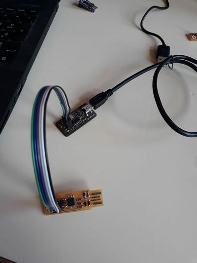
Programming the chip: test 4 - fabISP and Linux
We used this time the lab’s machine with linux installed.
I basically followed the same steps that I followed before (to install the software and build the firmware), and that are clearly explained in Brian’s tutorial.
This time no change in the Makefile is necessary.
In a nutshell, here are the command to use the terminal to flash the chip once it is connected:
make
make flash
make fuses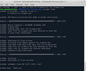
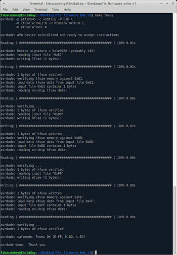
Finally, in three lines, everything worked perfectly!
If I test it on my windows laptop: it is recognized!
I can finally blow the reset fuse. It won’t be possible to reprogram the chip afterwards.
make rstdisblWe made First Christophe’s fabISP, and used his one to configure mine, It also worked
Last move: we can remove the jumper, and it’s done for this week!
Update week 7 and 9 - troubleshooting
When trying to develop my board in week 7, my programmer didn’t work.
The main error message was: avrdude: Error: Could not find USBtiny device (0x1781/0xc9f)
- Checking for shortcuts.
Nothing to declare!
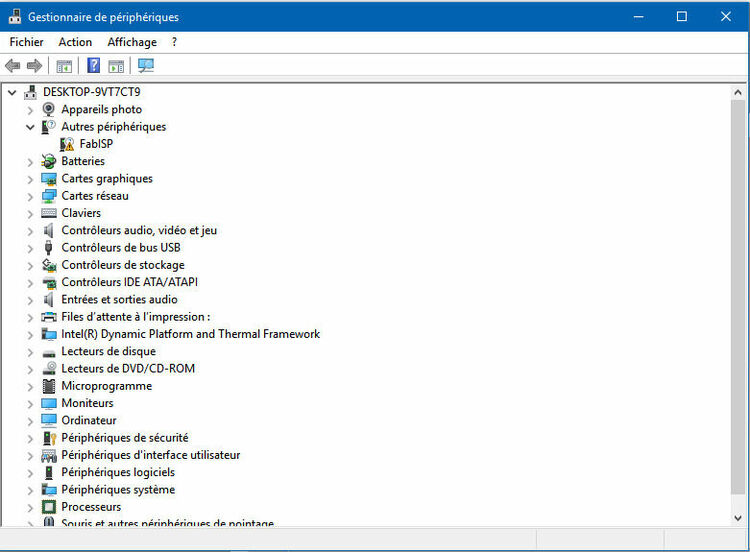
- Using
lsusbon a linux Machine
Multiple vendors USB tinyis recognized on the first try, bit not everytime…
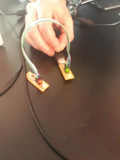
I checked the FTDI connector and there was connections problems.. Now it works!
- Retrying to program my hello board made in week 7
I got a new error message!
fabacademy@EnolaGay:~/Desktop/test2$ sudo make -f hello.ftdi.44.echo.c.make program-usbtiny-fuses
[sudo] password for fabacademy:
avr-objcopy -O ihex hello.ftdi.44.echo.out hello.ftdi.44.echo.c.hex;\
avr-size --mcu=attiny84 --format=avr hello.ftdi.44.echo.out
AVR Memory Usage
----------------
Device: attiny84

Program:     758 bytes (9.3% Full)
(.text + .data + .bootloader)

Data:         64 bytes (12.5% Full)
(.data + .bss + .noinit)


avrdude -p t84 -P usb -c usbtiny -U lfuse:w:0x5E:m


avrdude: error: usbtiny_transmit: error sending control message: Protocol error
avrdude: initialization failed, rc=-1
         Double check connections and try again, or use -F to override
         this check.


avrdude: error: usbtiny_transmit: error sending control message: Protocol error

avrdude done.  Thank you.

hello.ftdi.44.echo.c.make:31: recipe for target 'program-usbtiny-fuses' failed
make: *** [program-usbtiny-fuses] Error 1- Let’s recheck the FTDI connector… I realize that I assembled it in a very unstable way…
now it works!
fabacademy@EnolaGay:~/Desktop/test2$ sudo make -f hello.ftdi.44.echo.c.make program-usbtiny
avr-objcopy -O ihex hello.ftdi.44.echo.out hello.ftdi.44.echo.c.hex;\
avr-size --mcu=attiny84 --format=avr hello.ftdi.44.echo.out
AVR Memory Usage
----------------
Device: attiny84

Program:     758 bytes (9.3% Full)
(.text + .data + .bootloader)

Data:         64 bytes (12.5% Full)
(.data + .bss + .noinit)


avrdude -p t84 -P usb -c usbtiny -U flash:w:hello.ftdi.44.echo.c.hex

avrdude: AVR device initialized and ready to accept instructions

Reading | ################################################## | 100% 0.01s

avrdude: Device signature = 0x1e930c (probably t84)
avrdude: NOTE: "flash" memory has been specified, an erase cycle will be performed
         To disable this feature, specify the -D option.
avrdude: erasing chip
avrdude: reading input file "hello.ftdi.44.echo.c.hex"
avrdude: input file hello.ftdi.44.echo.c.hex auto detected as Intel Hex
avrdude: writing flash (758 bytes):

Writing | ################################################## | 100% 0.52s

avrdude: 758 bytes of flash written
avrdude: verifying flash memory against hello.ftdi.44.echo.c.hex:
avrdude: load data flash data from input file hello.ftdi.44.echo.c.hex:
avrdude: input file hello.ftdi.44.echo.c.hex auto detected as Intel Hex
avrdude: input file hello.ftdi.44.echo.c.hex contains 758 bytes
avrdude: reading on-chip flash data:

Reading | ################################################## | 100% 0.80s

avrdude: verifying ...
avrdude: 758 bytes of flash verified

avrdude: safemode: Fuses OK (E:FF, H:DF, L:5E)

avrdude done.  Thank you.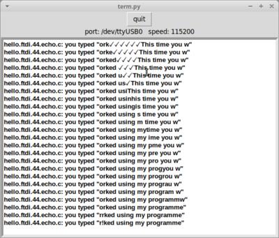
Conclusion: Always check your connections and connectors!