3. Computer Aided design
Assignment
- [x] model (raster, vector, 2D, 3D, render, animate, simulate, …) a possible final project, and post it on my class page
Summary
Again, everything to be learned and practiced: the only software I ever used for 3D modelling is SketchUp. Other simulation programs I learned in another live are Samcef and ANSYS ( finite element software, for mechanical or electrical modeling). So, here, I learned how to:
- use FreeCAD and Fusion360
Files are available here, here and here
Introduction
The idea is to understand and use several methods for modelling objects:
- 2D modeling : There are two main type of image files: Raster and Vector
Raster images are created with pixel-based programs or captured with a camera or scanner. They are more common in general such as jpg, gif, png. Drawback: when raster images are scaled, quality is lost and they become blurry, as each pixel becomes larger or photo editing software attempts to compromise by adding in colored pixels.
PNG, JPEG, JPG are raster image format
Vector graphics are made up of paths, each with a mathematical formula (vector) that tells the path how it is shaped and what color it is bordered with or filled by, and are common for images that will be applied onto a physical product. Vectors can be infinitely scaled without loss of quality.
SVG (Scalable Vector Graphics) is the vector graphics format
-
3D modeling: “In 3D computer graphics, 3D modeling is the process of developing a mathematical representation of any surface of an object (either inanimate or living) in three dimensions via specialized software” (Wikipedia)
-
Further than physical rendering, simulation is an important step in design
“Simulation software is based on the process of modeling a real phenomenon with a set of mathematical formulas. It is, essentially, a program that allows the user to observe an operation through simulation without actually performing that operation. Simulation software is used widely to design equipment so that the final product will be as close to design specs as possible without expensive in process modification” (Wikipedia)
Tests
Gimp
I’ve installed Gimp2.10.8 , and follow the tutorial, but found it not really useful for what I need to do now, so I preferred to switch to InkScape for 2D drawing and FreeCAD and Fusion360 for 3D drawing.
Inkscape
I’ve started from a drawing in png format and vectorize it, and add some text. Before plotting, I get some help to check that all forms (drawings and letters) are properly closed forms.
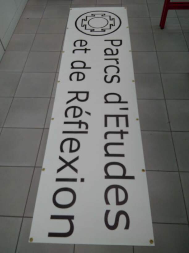
Even better: a colleague printed the drawing on a canvas, on a scale 1:1, e.g. 2m40 by 0m65:
Files are available here
FreeCAD
Download FreeCAD and follow tutorial
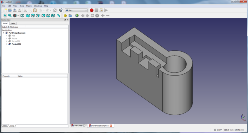
Let’s make a simple 3D structure to get used with the software, e.g. by reproducing the PartDesignExample.
File → New
Part Design
Create Body
Create Sketch
Sketcher
Sketch orientation ( XY plane eg)
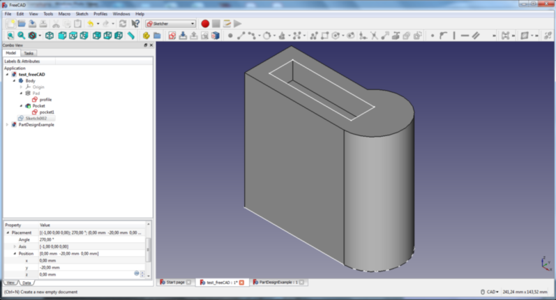
Start drawing with the different tools available: lines, arc,…and add tangential constraints ( selecting two elements) to make a profile
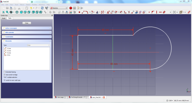
Start other sketches to make the pockets. the sketches can be created on any plane (XY, XZ or YZ) with an offset from the plane when needed.
Note that dimensions and constraints may be changed afterwards, solid created from the sketches are changed accordingly
Part Design
Extrude the sketch into a volume, along the normal to the plane, 100mm high (pad a selected sketch)
Create a cavity starting from the top with the next sketches (create a pocket with the selected sketch)
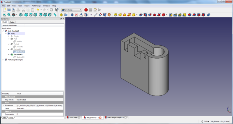
Space key toggles the visibility of the selected parts/sketches on the left menu… Nice feature
One frustrating issue is that FreeCAD stops from time to time unexpectedly....
Fusion360
Download Fusion360 and follow tutorial
My first idea was to recreate the same structure as in FreeCad, but I changed my mind and decided to redesign the 3D Fabacademy 3D logo, using parametric data:
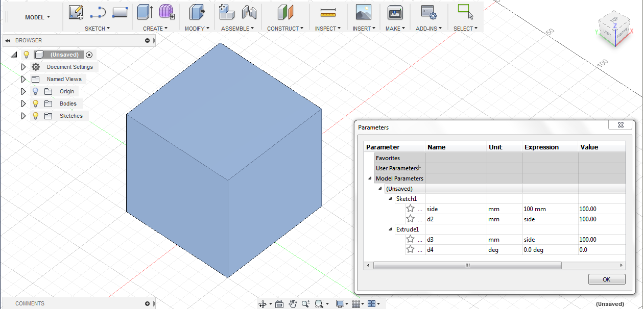
I start to make a square, centered at the origin, of 100mm by means of the command: Sketch → Rectangle → Center rectangle,
I perform an extrusion of 100mm: Create → Extrude.
In the menu Modify → Change parameters, I fix one side of the rectangle I call side and renamne all dimensions in function of this parameter to get a cube.
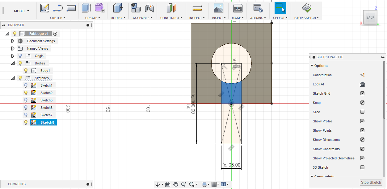
Place a circle (Sketch → Circle → Center Diameter Circle) in the center of one face, using diagonals as construction lines and setting a constraint to place the center of the circle at the crosspoint of both diagonals. Diameter is set equal to side divided by 2, and it is extruded on the whole height of the cube to make a hole (cut).
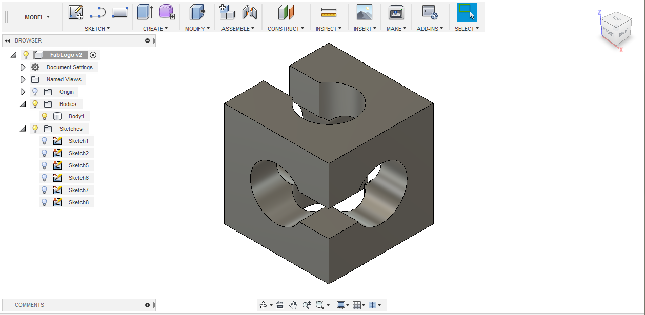
Repeat for the three directions:
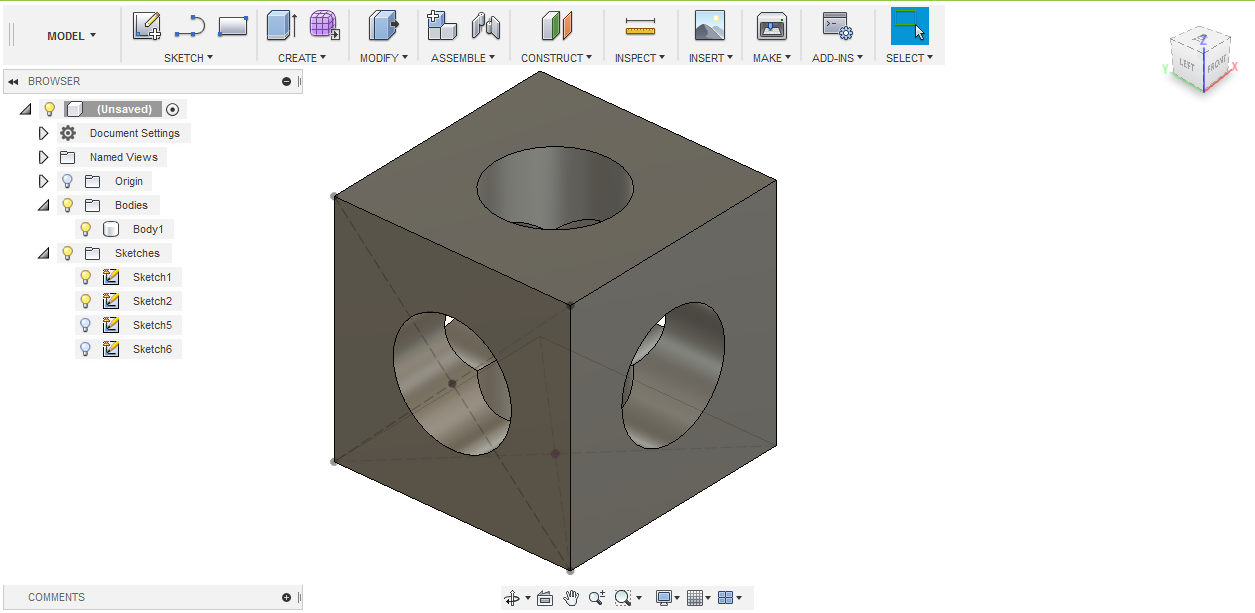
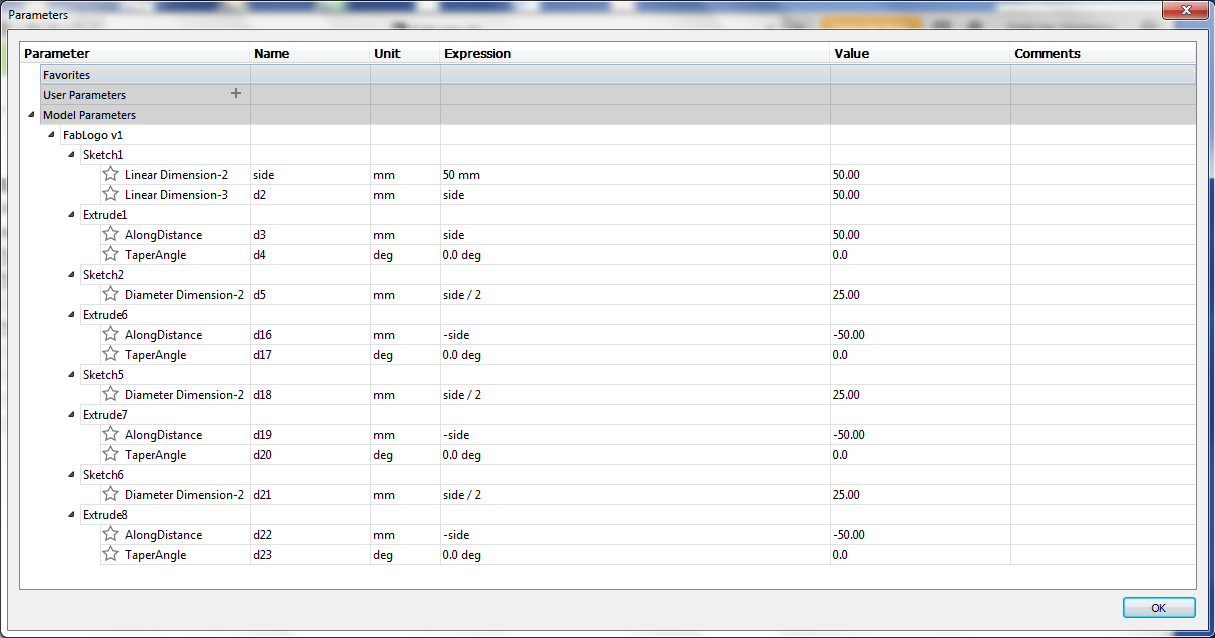
Place a rectangle of width side/4 and height side, on one face, centered by means of a constraint, on the middle of an edge, and extrude part covering the cube, inside the cube on a distance of side/2
Repeat for the three directions:
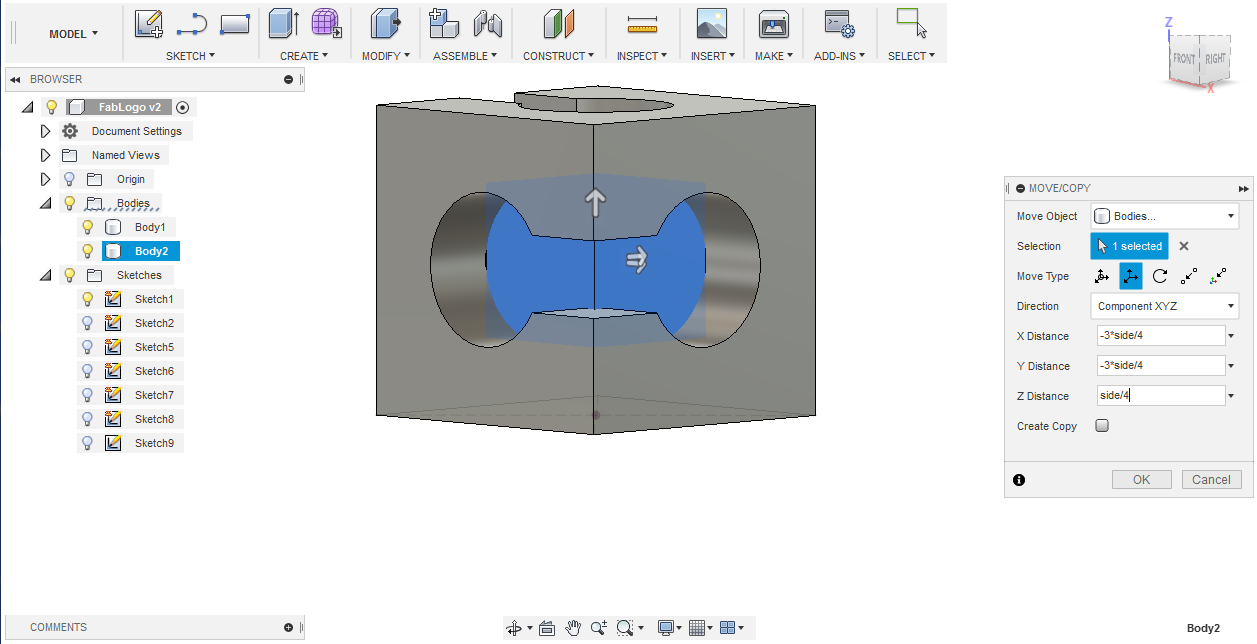
Finally, place a cube of side side/2 at the center of the body previously obtained and cut it from the latter. To do this, I place by constraint a cube outside the original body and translate it to the center of the latter.
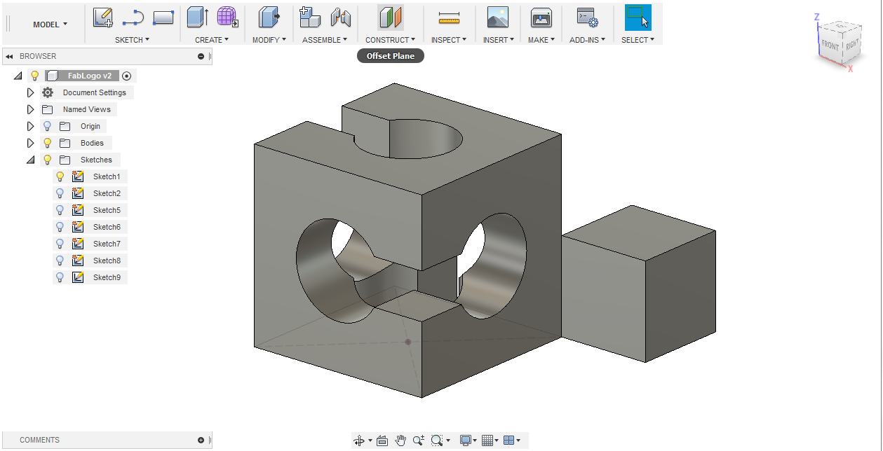
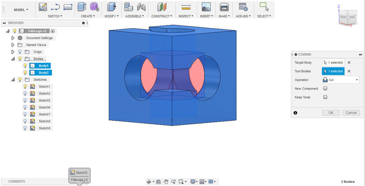
By combining the two bodies (cut), we get our final structure:
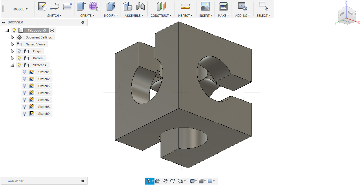
Thanks to the parametric construction, changing the side of the original cube leads to automatic adaptation of the whole structure.
An OBJ file is saved to use in 3D print.
THe Fusion360 archive and the OBJ version are available here
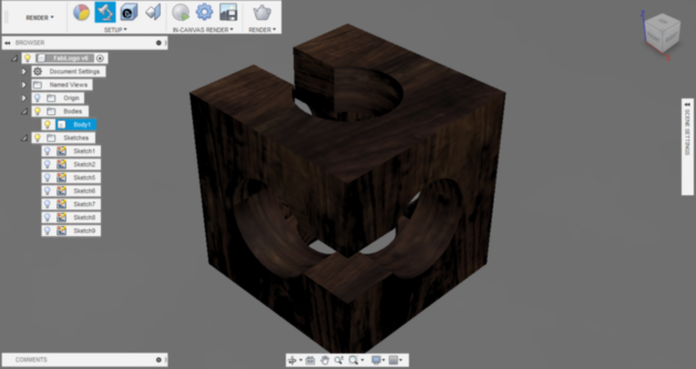
And finally, rendering is used to play with the appearance, eg:
Still to do if I had time....
Nothing more for the moment, or eventually some animation of the designed structure.