4. Computer controlled cutting
Assignment
-
[x] group assignment: characterize your lasercutter, making test part(s) that vary cutting settings and dimensions
-
[x] individual assignment: cut something on the vinylcutter design, lasercut, and document a parametric press-fit construction kit, accounting for the lasercutter kerf, which can be assembled in multiple ways
Summary
What I learned here are the several steps required to use a laser cutting machine … :
- design of a parametric 3D structure on a CAD software ( eg FreeCAD)
- transfer it into 2D DXF format to the software installed, define the correct driver parameters - on the PC controlling the cutting machine
- Check the settings of the machine and the program to work with the chosen material
And on a vinyl cutting machine, much more simple:
- Choose correct settings prior to printing, depending on material, again, and including file format read!
Last but not least, team work for the group assignment helped increase productivity, by sharing knowledge and dividing tasks
Files are available here (for the laser cut) and here (for the vinyl cut)
Notes and Introduction
a few notes: take care that some materials are incompatible with some processes, eg. do not use PVC in laser cutting, toxic gases are produced; metal cutting requires specialized laser cutting machines.
Group Assignment
We deploy three tests:
-
Press fit, using two combs with different teeth width (Process 1)
-
Power and speed parameters, using color mapping to cut rectangles at different settings values (Process 2)
-
Kerf width on a straight rectangle of known length cut in 10 equal pieces (Process 3)
Files are available here.
Resources available @Fablab ULB:
- The laser cutting machine is a CO2 60W EPILOG MINI, with a useful surface of 30x60 cm, interfaced with CorelDraw
- Available material for the test is a 3mm MDF wood plate.
- The vinyl cutting machine is a [Silhouette Cameo] (https://uscutter.com/static/PDFs/cameo_manual.pdf)
- Available material is Vinyl rolled up sheets of several colors, and thin cardboard
Process 1:
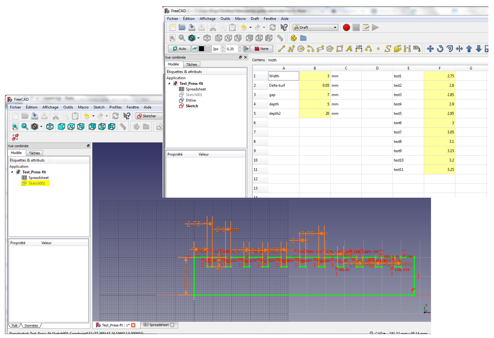
A parametrized comb structure is defined in the FreeCAD Sketcher module, using a parametrization based on the width plate as basic parameter (all parameters defined in Spreadsheet)
- Plate width: 3mm (alias: width)
- 11 variable slots sizes varying from with-0.25mm to width+0.25mm, by step of 0.05mm (aliases: test1 to test 11 variables)
- depth of the teeth: 5mm
- overall depth of comb : 20mm
- distance between teeth (gap): 7mm
Here is the result:
In a second stage, the file is exported to DXF format (File → Export → Autodesk DXF 2D ) to be read by CoralDraw, the software used to communicate with the laser cutter. Note that the preference Allow FreeCAD to automatically download and update the DXF libraries must be turned on in FreeCAD.
In CoralDraw:
- The width of each slot is added as text, to be engraved on the MDF plate. Do not forget to convert text to curve, and to change the text thickness to 0.2mm to make it more readable.
- Lines to be cut need to be defined as “ligne très fine” (very thin lines)
- Lines to be engraved do have a defined thickness
- When file is ready to be sent to printer, define the settings in the EPILOG driver in CorelDraw:
The standard settings for wood are given below (extract from EPILOG manual):
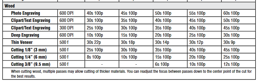
For a 60W machine:
- Text Engraving: raster, 600DPI, speed: 45, power 100
- Cutting 3mm: vector,pulse frequency: 500, speed 40, power 100
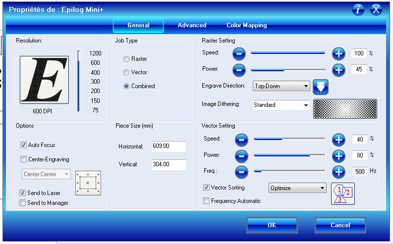
As both engraving and cutting are used, do not forget to check the option combined!
Printer setup:
Place the MDF wood plate on the honeycomb support in the printer Caution: take care to start the design by defining the origin point through manual settings if needed ( On Epilog mini dashboard: set manually zero position (pointeur > x/y off > (move manually the laser pointer) > définir origine))
Do not forget to start the gas extractor and its pump, altogether with the laser printer itself!
Press Go on the dashboard when Job, sent from the controlling PC, can be started…
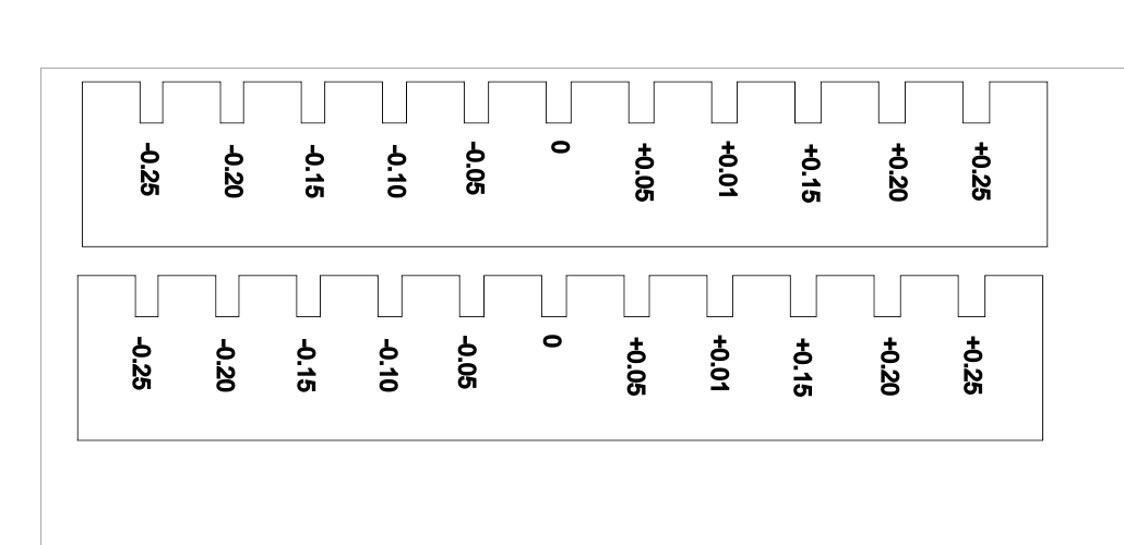
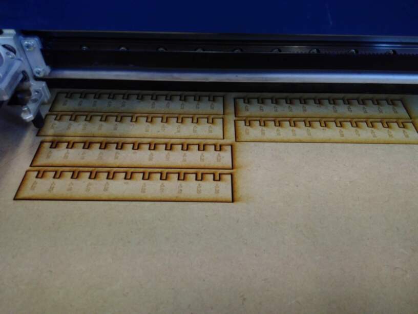
We’ve tried three sets of tests:
-
First test (top left): Power 80, speed 40 : comb is not completely cut (power too low)
-
Second test (top right): Power 100, speed 20: comb is completely cut but wood is burnt (speed to slow)
-
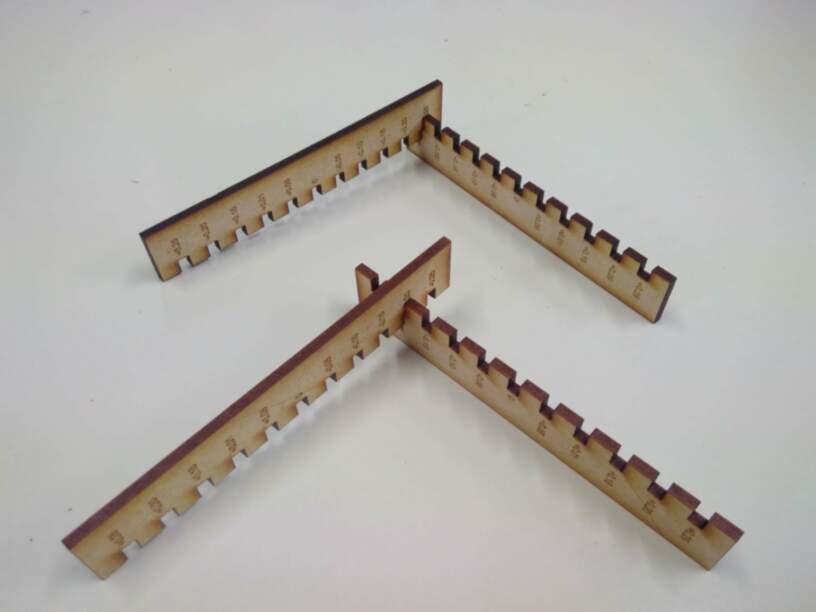
Third test (bottom): Power 100, speed 40 (standard settings): comb is cut and wood is in better state!!! Definitely the best choice!
 Concerning the best press fit, we see that for the second test, it is the slot -0.25mm, whereas for the third test, the best fit is -0.20mm.
Process 2
In this test, a simple structure of a 4x3 rectangles is directly drawn in CoralDraw, with power (p) and speed (s) as parameters of the color mapping
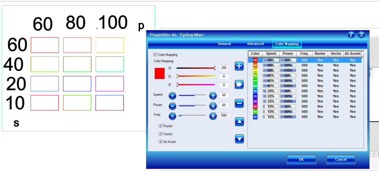
The result is that for speeds 10 and 20, all rectangles are really cut, for speed 60, no rectangle is cut. For speed 40, only the rectangle cut @ 100 is cut (standard settings!!)
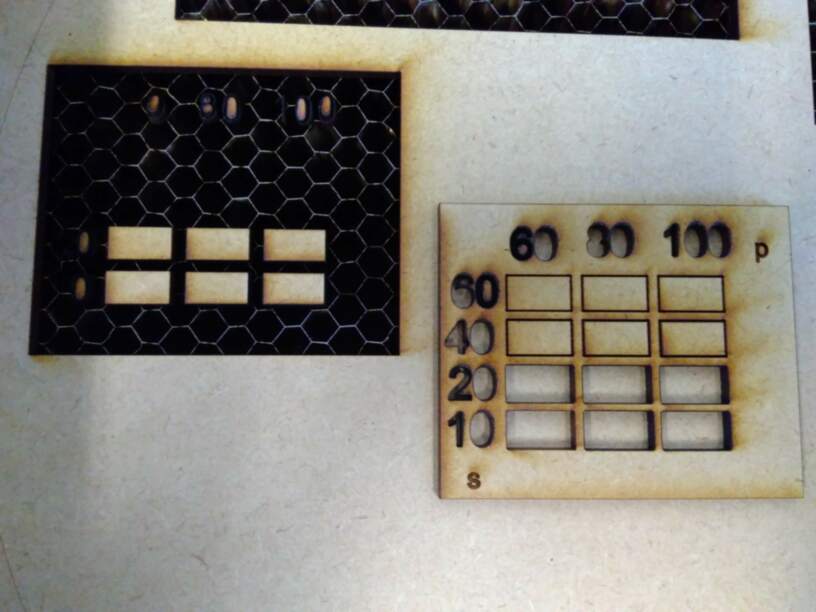
Difficulties encountered: there has been a superposition of rectangular frame at creation that lead to two passes of the laser! Failed! The combination of raster, vector and color mappings is more difficult than expected, and forms that were meant to be engraved were finally cut ( the numbers, colored in black, not used in color mapping were thicker than expected!!).Be carefull in this case!
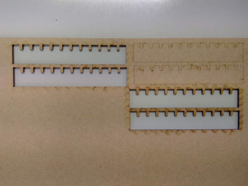
Process 3
In this test, a rectangle of 100mm is drawn in Coreldraw, and then cut in 10 equal pieces.
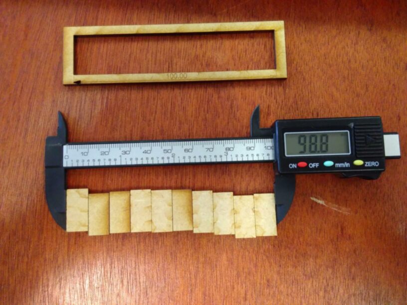
Measuring the remaining width (98.8mm) on small rectangles after cut,and remaining rectangular hole (99.6mm), the kerf may be estimated to be: (99.6-98.8)/11 = : 0.11mm (TO CONTROL)
This latest test didn’t bring any specific difficulty.
Job done!
Summary
Optimal parameters for 3mm MDF wood plate cutted with a CO2 60W EPILOG MINI
| Parameter | value |
|---|---|
| Cut power | 100 % |
| Cut speed | 40 % |
| Cut frequency | 500 Hz |
| Engraving power | 100 % |
| Engraving speed | 45 % |
| Engraving quality | 600 DPI |
| Kerf width | 0.11 mm |
| Optimal fit | 3 - 0.20 mm |
Individual Assignment
Laser Cutting
step 1: Modelling of structure
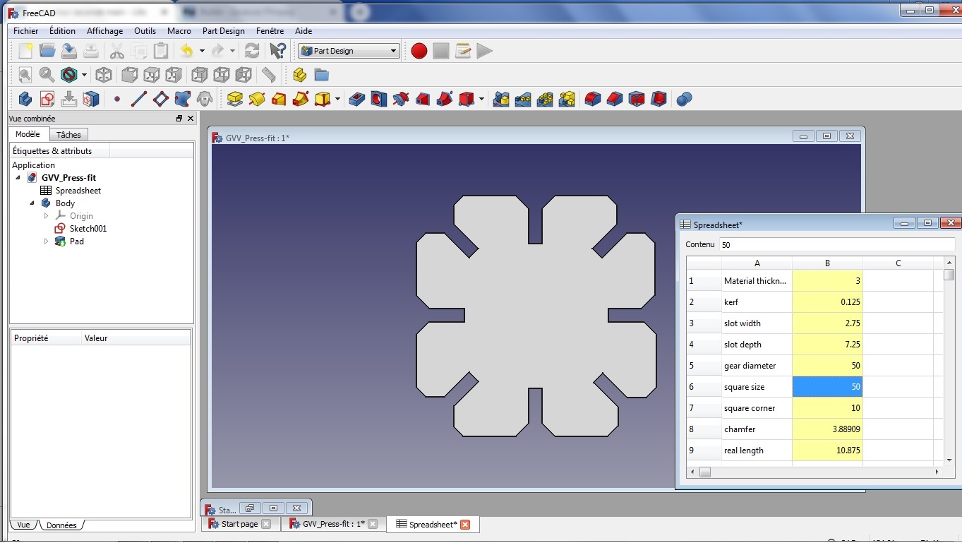
The objective here is to develop my own press-fit test. I work with FreeCAD, the software I learned last week, but this time, I try the parametric modelling, e.g., defining some parameters in a spreadsheet, and using these parameters as constraints for the sketch. The only independent parameters are the thickness of the material used, the kerf and the global size of my piece.
Constraints on the length of several lines are given below:
| Parameter | value | alias |
|---|---|---|
| Material thickness | 3 mm | thick |
| Kerf | 0.125mm | kerf |
| slot width | thick -2*kerf = 2.75 | s_w |
| slot depth | side*2/10 -s_w =7.25 | sl_d |
| square size | 50 | side |
| square corner | side *2/10 = 10 | corner |
| chamfer | sqrt(2)*s_w = 3.89 | cham |
| real length | (side2/10)-s_w3/2) = 10.875 mm | length |
Other types of constraints are: symmetries against X and Y axes to center the whole piece and angular position of lines to ensure a good chamfren
This leads to a structure without any degree of freedom left, and 166 constraints
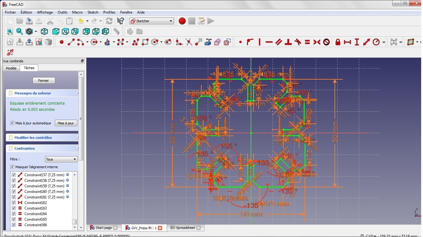
Removing the measurements, to make a clearer view:
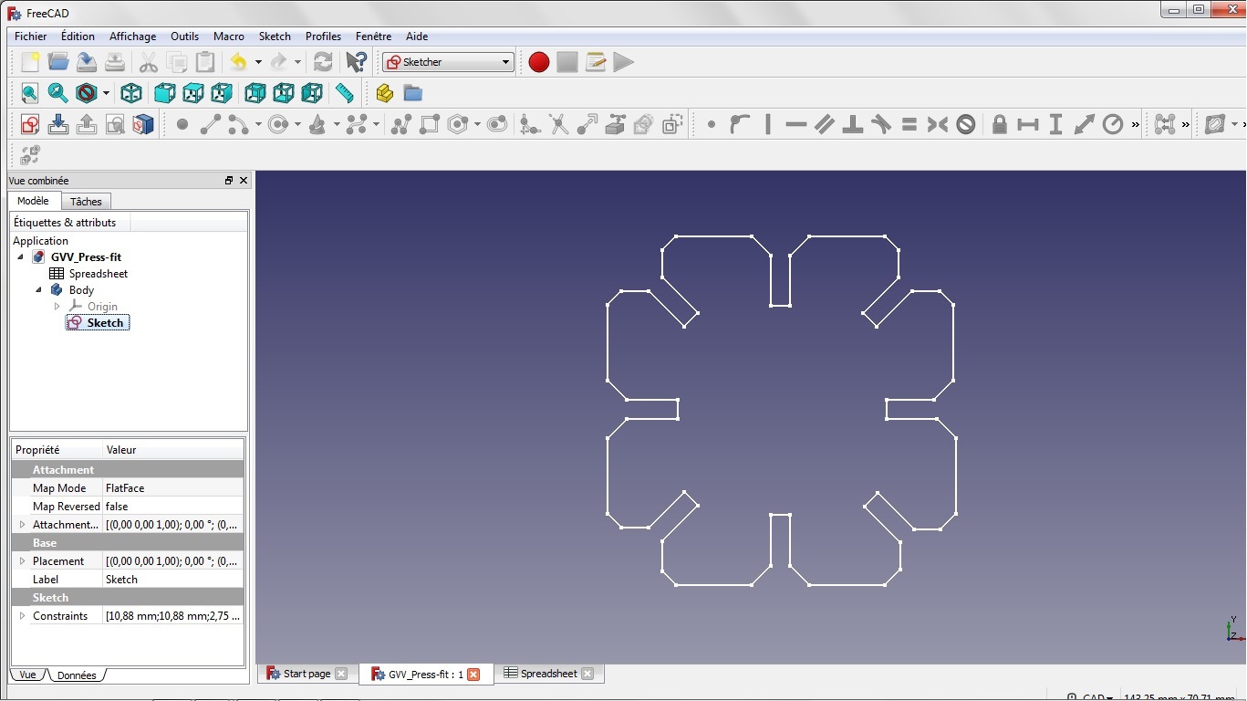
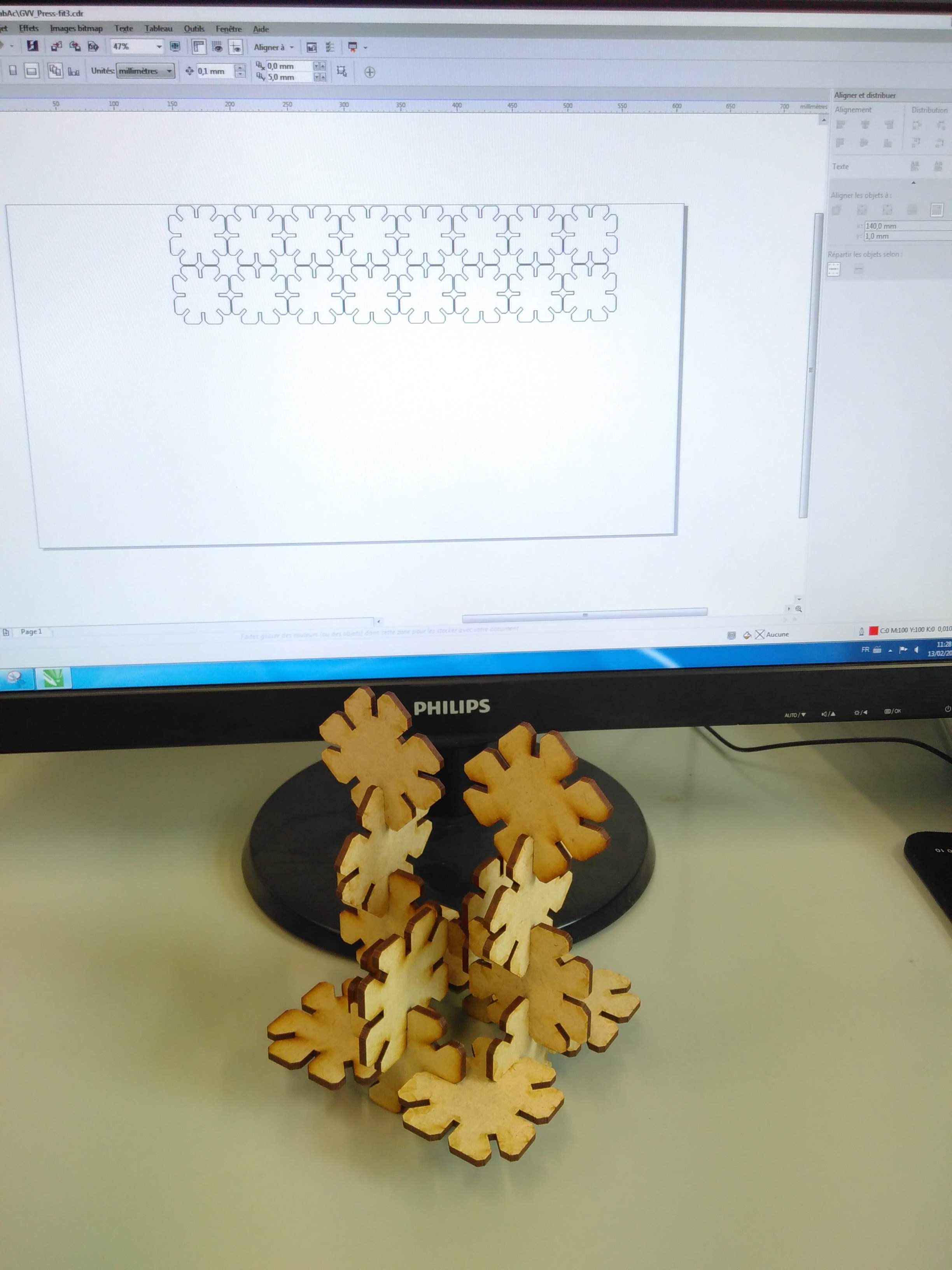
After completion of the sketch, I create the body ( 3D structure) and start playing with the parameters,e.g. choosing a square size of 50mm and then of 100mm. by changing this parameter only, the whole drawing is adapted as shown below:
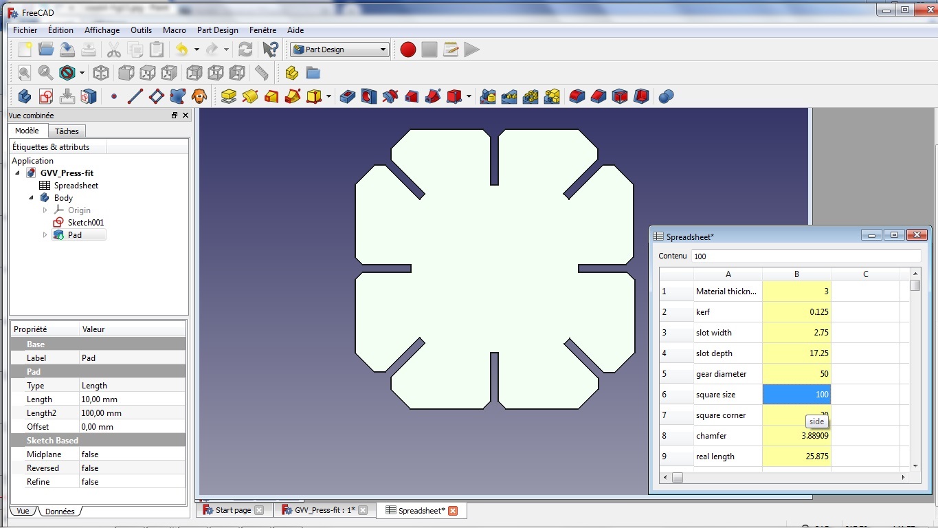
The files are available here.
Difficulties encountered: Going from one workbench to the other ( part design / sketcher / spreadsheet) proved to be a struggle before founding the right way to proceed to avoid crashes of FreeCAD and correct construction of the parts!! There must also be a more efficient way to build the different constraints on the structure than what I’ve done, as it took me a quite long time.
Finally, I export these two examples to a 2D DXF file, to be loaded in CoralDraw, on the PC controlling the laser cutting machine.
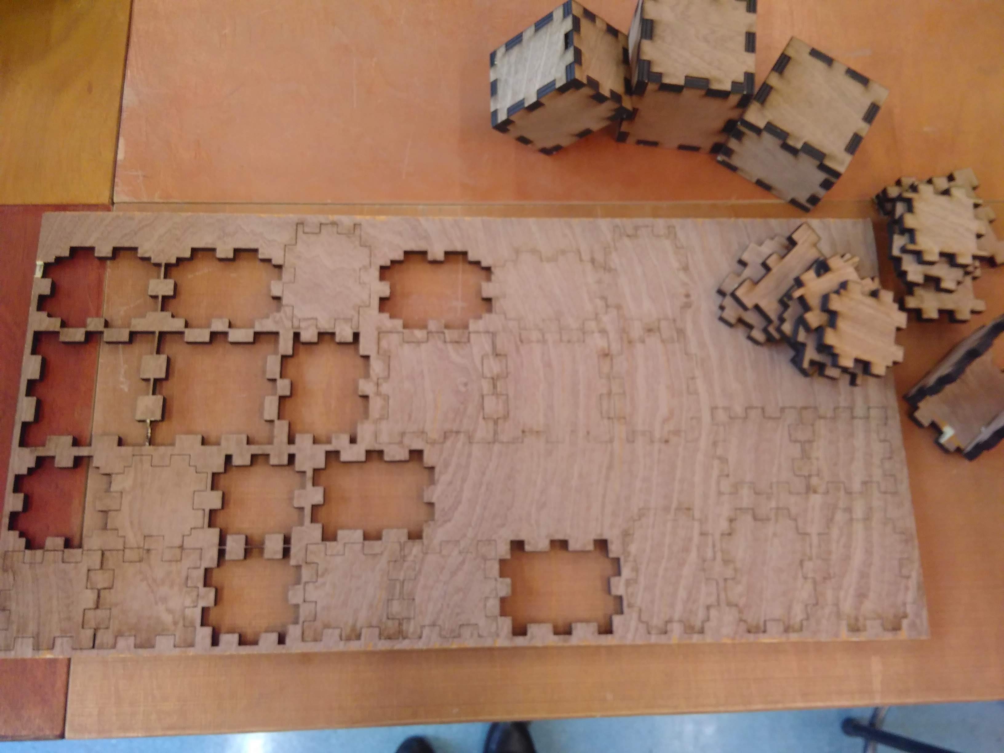
step 2: Cutting
In order to build a 3D structure I need to duplicate the basic shape several times. In order to do this, I use the copy and paste command (which superimpose the structure to itself) and move the copied shape a little bit further on the page…in such a way to avoid superposition of lines. In order to use a previously used MDF plate, there are two workaround not to start at origin (0,0). The first has been explained in the group assignment, the second I use here is just to move the shapes on the page in X /Y axis from the software itself (selecting and dragging the sahpe to the desired distance, or adding a + distance in the point refernce in top menu).
I use the same settings for the laser cutting machine in CorelDraw as for the group assignment…
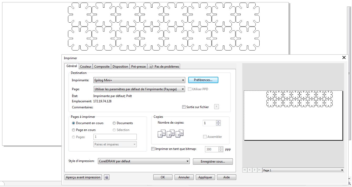
Here we have:
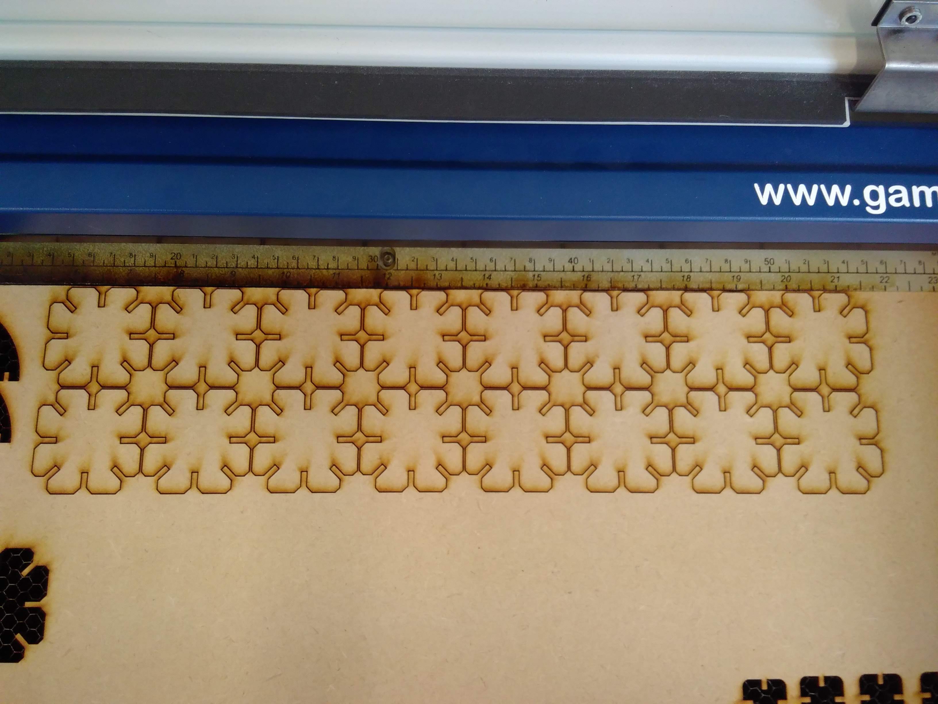
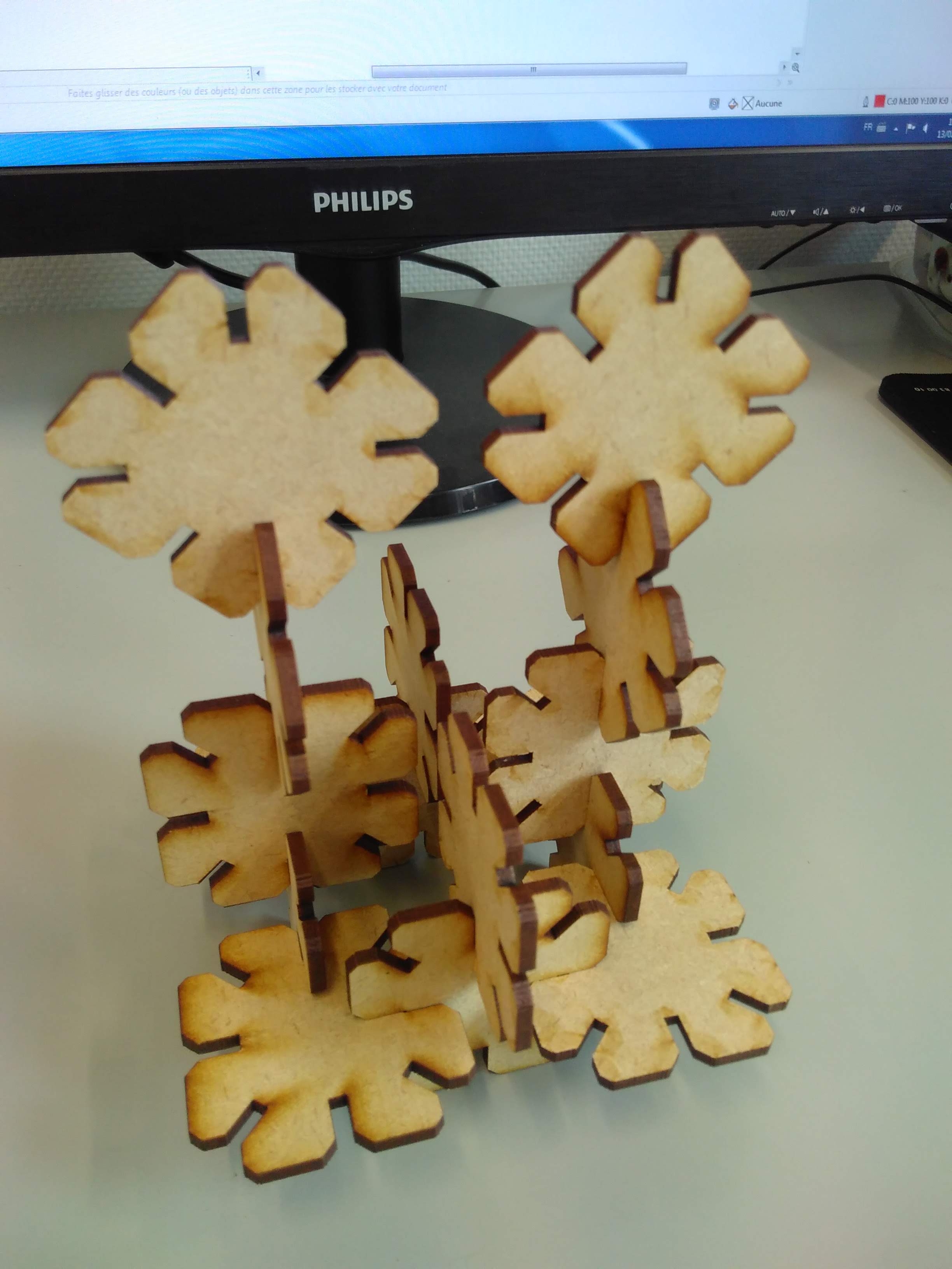
The files are available here.
Difficulties encountered: I had to increase the slot width from 2.75mm to 2.80mm, as the first three test shapes I cut ( as test) were fitting a little bit too tight.
Vinyl Cutting
step1: Modelling
The first difficult point is to choose a drawing…
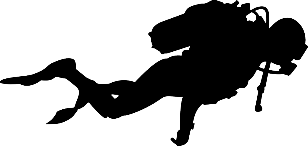
I decided to start with a one color drawing, a scuba diver silhouette; I first isolate the silhouette and turn it in dark black ( with a little help of paint), use then Inkscape to create the cutting path of the silhouette I will later on use in Silhouette Studio, the software from which the cutting machine is controlled…
Tricky job! Here are the steps in Inkscape:
* File → Import ( I leave the standard settings)
-
Path → Trace bitmap(I use multiple scans, based on Color, 2 passes only, removing background) -
Remove the original layer
-
CTRL+SHIFT+F to open the Fill dialog box
-
Fill: remove the filling by checking the cross
-
Stroke paint: check the simple stroke check box ( next to the x)
-
Stroke style: enlarge a bit the contour line that nows appears…
-
Check that the page dimension is large enough to surround the drawing (
File → Document properties) -
Save the new format!!

step2: Cutting
In order to get used to the vinyl cutting machine, I first start from a model included in the library of the Silhouette Studio. Here are the steps I followed: * Install Silhouette Studio ( version 4.1) on PC, connect the Silhouette Cameo through its USB cable
-
Place the vinyl sheet on the cutting mat (do not forget to remove the protection transparent sheet on it)
-
Load the mat, using control panel on Printer
-
Create something by placing the figures on the page (DESIGN tab)
-
Choose the settings (SEND - ENVOYER tab): first choose material ( here vinyl mat), action (cut) and tool (silhouette lame, there is no other choice here)
-
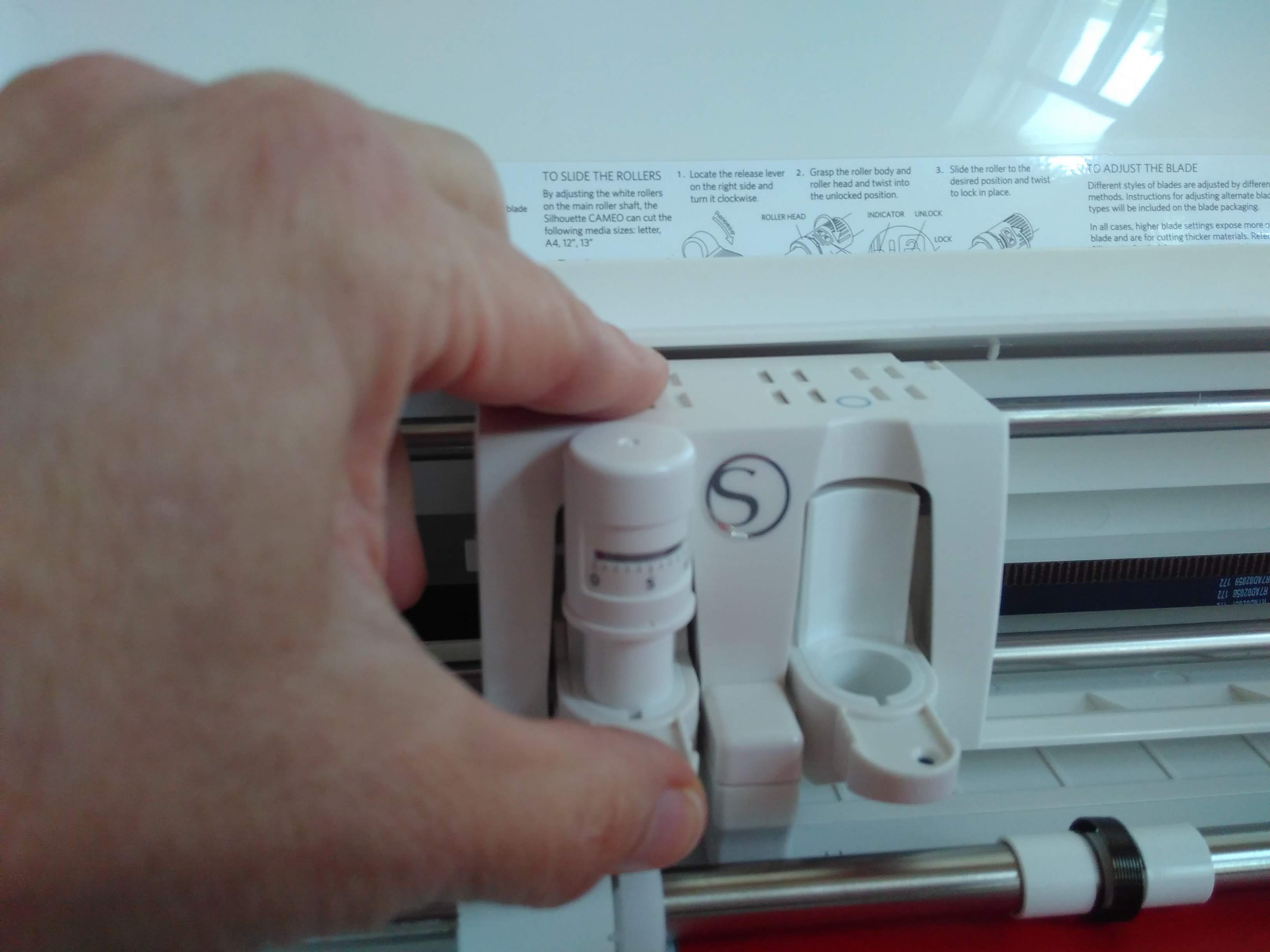
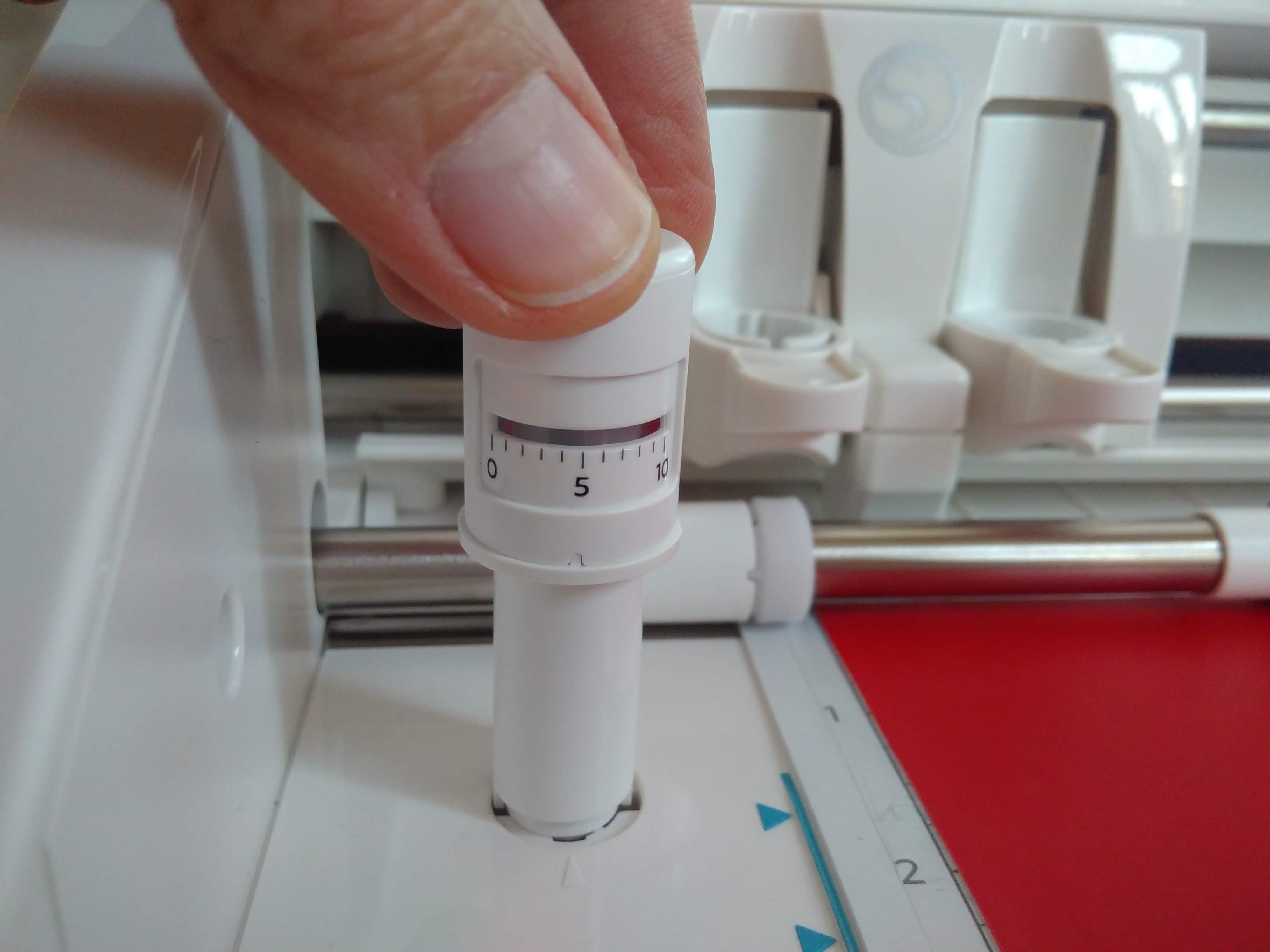
Remove the cutting tool from its support, calibrate it tool on the proposed number (1) obtained from the material choice ( by turning the base cylinder till the red line stands in front of number 1), and place it back, pressing firmly enough!!
-
Notice the default parameters proposed : speed 5, force 10, passes 1.
- When ready, send to cutting printer!
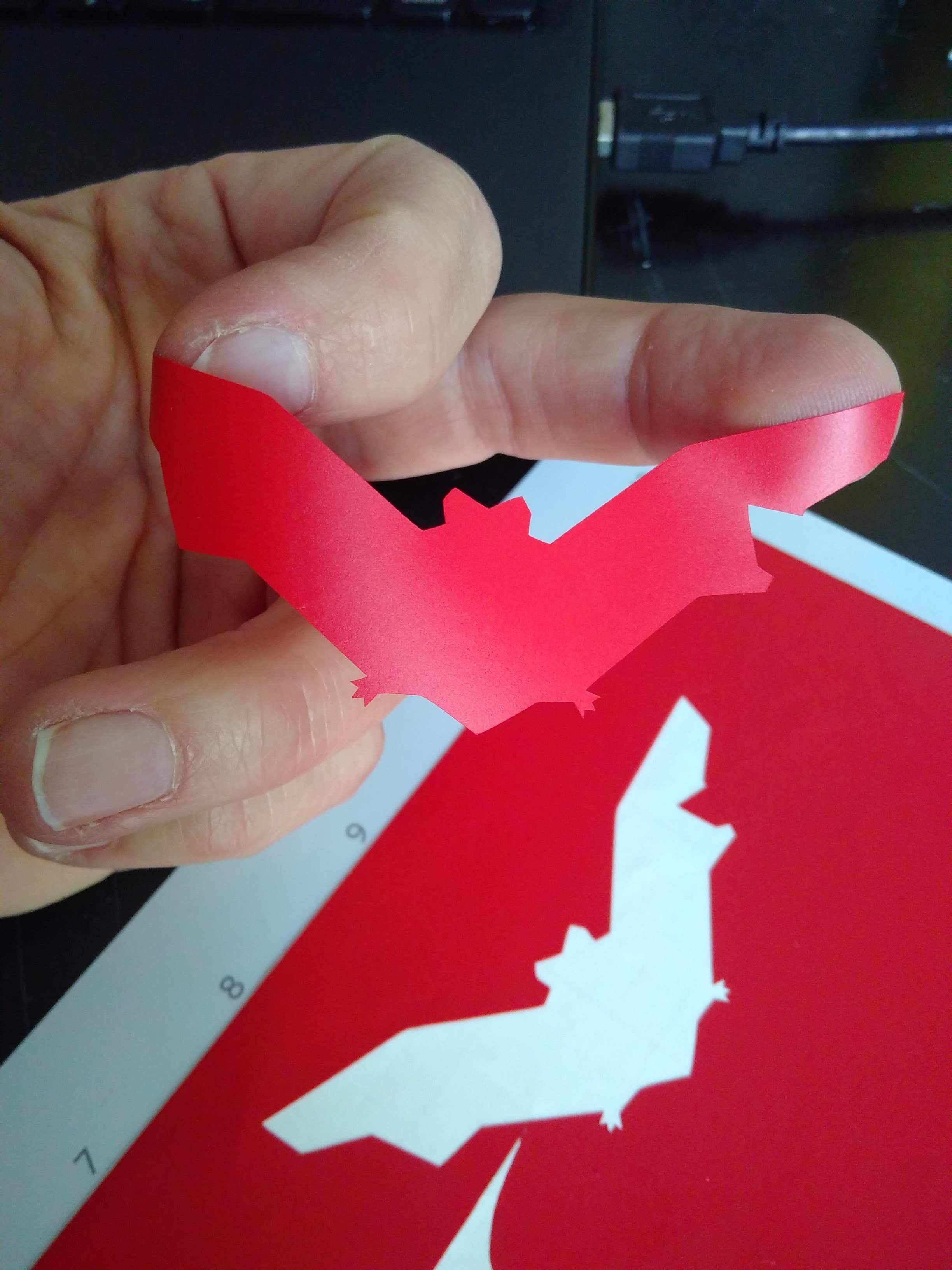
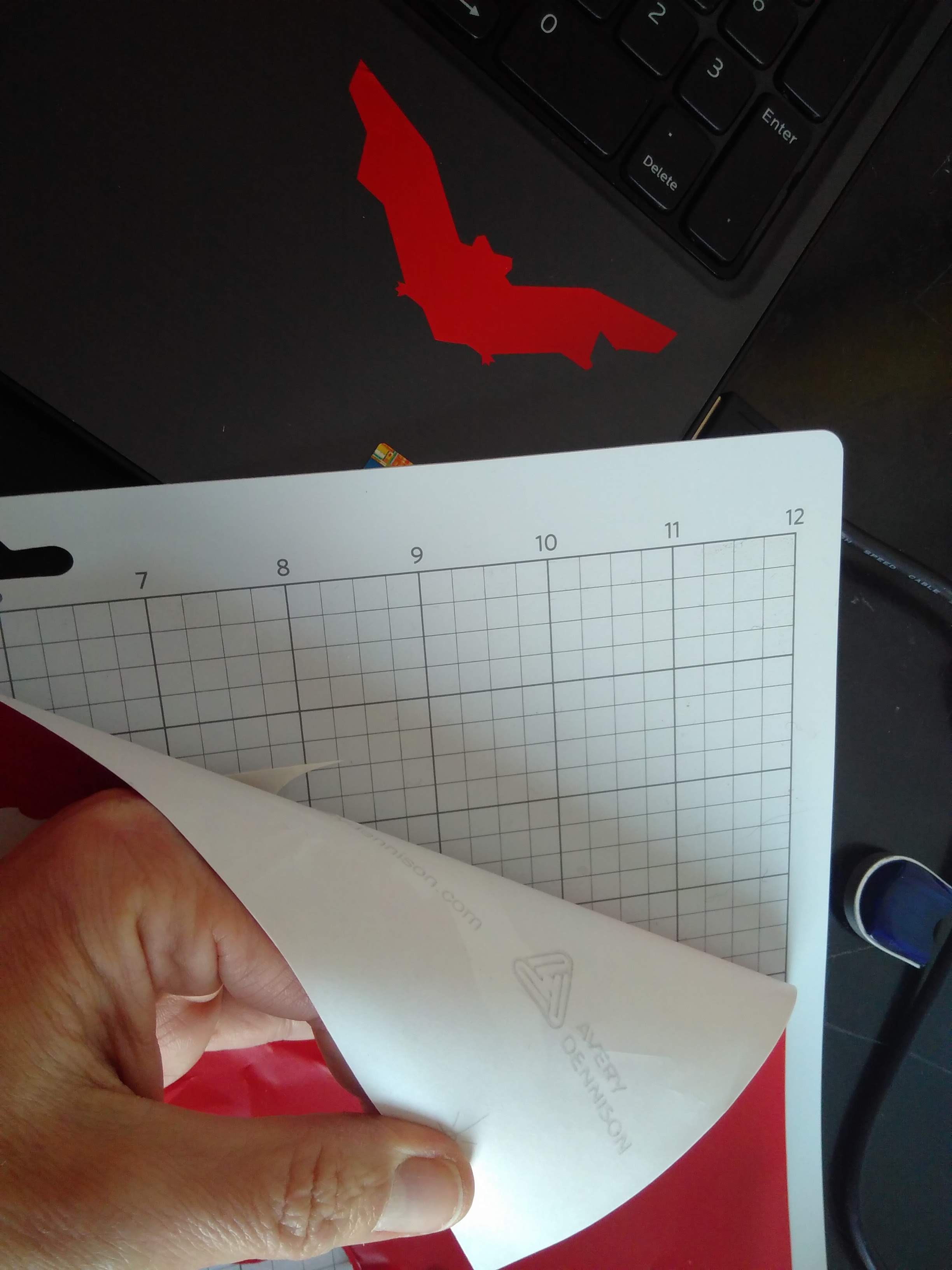
Here is the first trial result: The back support is not cut, but nevertheless, it is scratched, so next test, I’ll try to reduce a bit the force. Shape is small, easily removable from the support with bare hands..
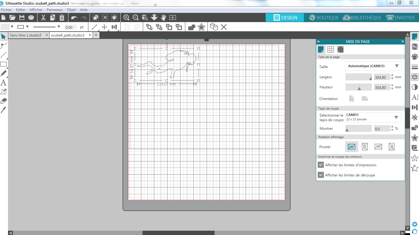
I’ll now try with my own drawing ( the scuba diver). First difficulty encountered is that the Silhouette Studio 4.1.9 requires vectorial drawing, but does not support SVG format!! So, back to Inkscape to transfer the drawing in DXF format!!
Force is reduced to 8.
See settings below:
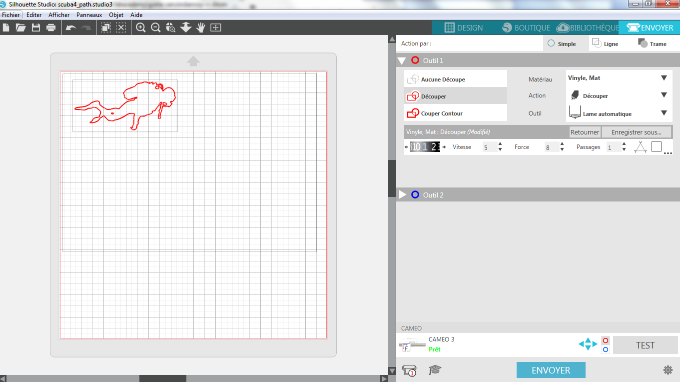
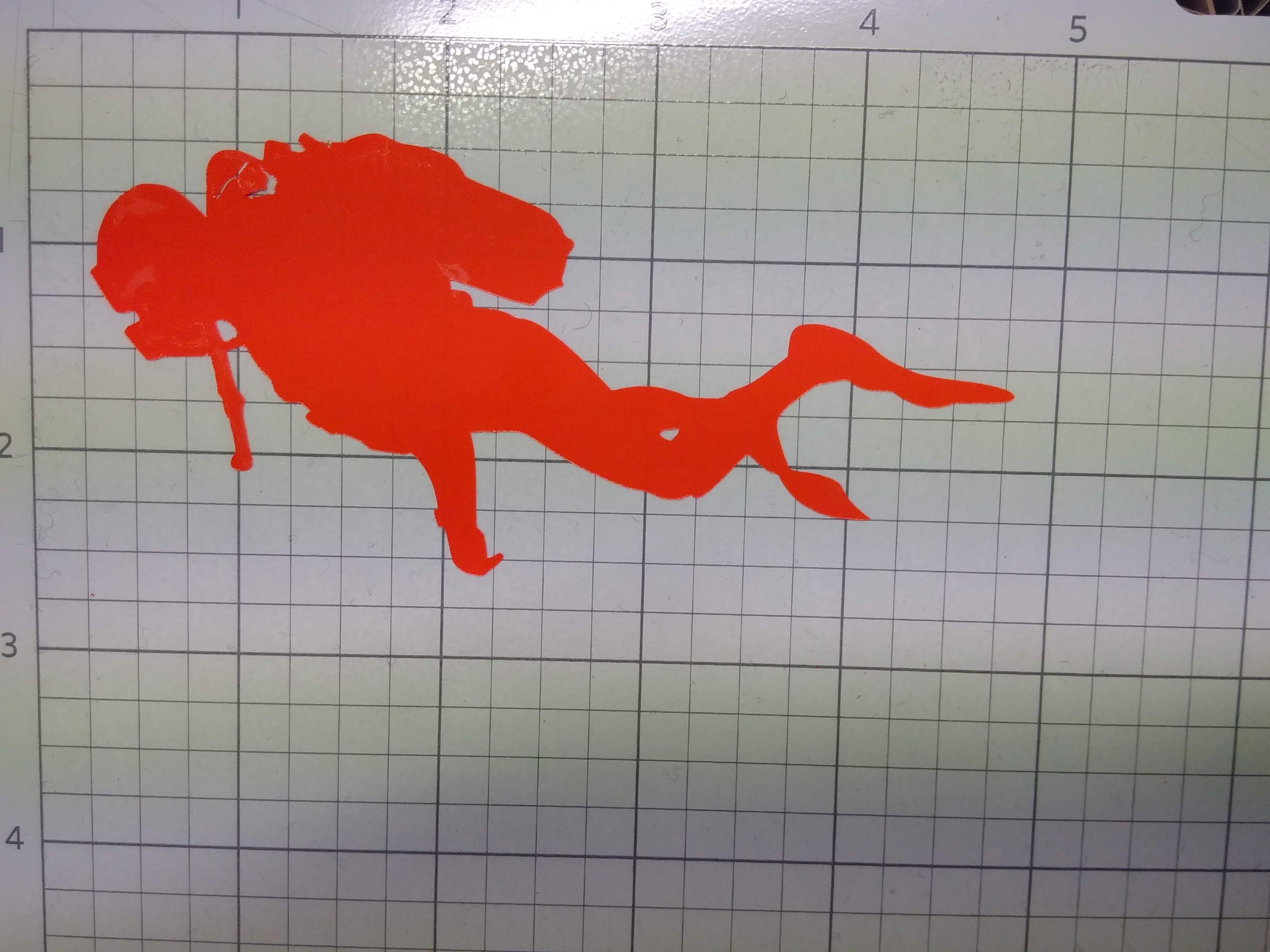
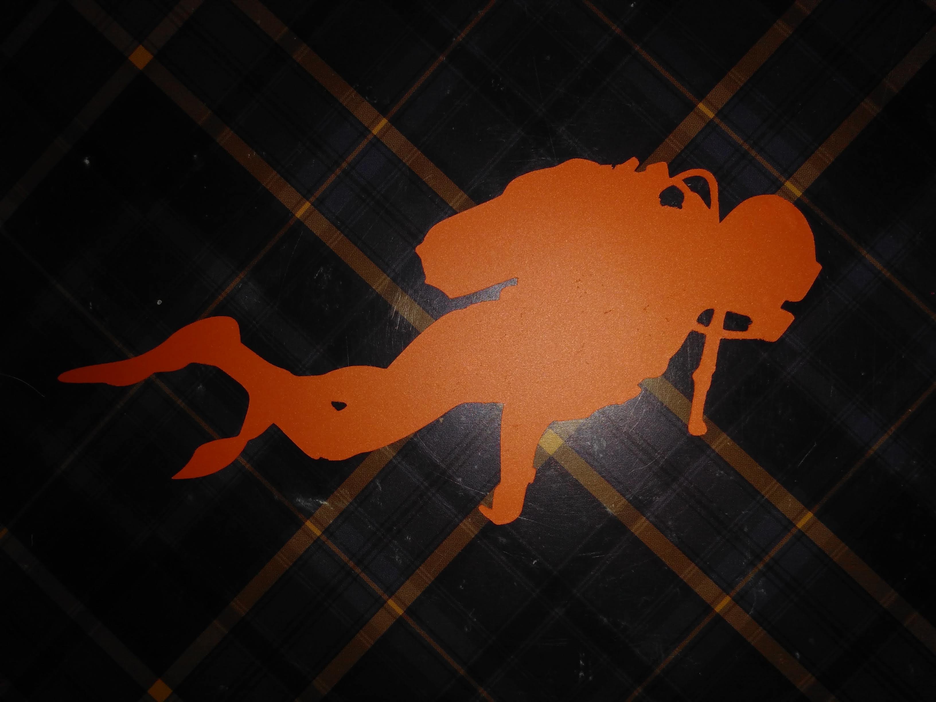
When cut, the shape has really small details, so I decided to transfer it first to an adhesive plan, typically the cut mat, remove the undesired parts and then transfer it again on final support ( my notebook!!). Take care of thinner parts of the material!
Here we have:
Extra job done....
I helped Thierry to cut its shapes in 8mm thick plywood. Interesting point here is that given the non really flat plate (bought in a local DIY store), the parameters given for 9.5mm wood (speed 10, power 100) was not enough to properly cut the plate in some places.
Still to do if I had time....
LASER CUTTING: I’d like to try engraving on glass and cutting light material as balsa to make a deployable structure. Engraving or cutting hard material in such a way that the structure could gain in flexibility could also be a option.
VINYL PRINTING: I’d like to play with several colors at once. Would this be possible? Answer is yes…when I gain some time…