5. Electronics production
Assignment:
-
[x] group assignment: characterize the design rules for your PCB production process
-
[x] individual assignment: make an in-circuit programmer by milling the PCB, check if you can program it, then optionally try other PCB processes
Summary
Concerning making PCB, I’ve been working with etching process, so milling process is a new topic for me…I’ve learned to use a Bantam milling machine.
Concerning embedded programming, I’ve been working with Keil µvisionIDE and Atmel Studio’, both being graphical IDE.
So I decided to go for two new IDE; Arduino and WinAVR. Concerning the latest, it has been a hard learning curve, as the portability of original Unix/Linux softwares on Windows always leads to surprises…
Group assignment:
Material and setup
We use the Bantam PCB milling machine
The first thing is to install driver available here.
Traces width characterization
Getting an svg image
We use the png file provided by Neil. The software only accepts images in svg, so let’s play with image format!
- Test 1 (failed): using only Inkscape: Using only inkscape, the first step is to use the function trace bitmap to vectorize the image. The image can then be exported as svg. Problem: The image scale is lost between inkscape and the Bantam software.
- Test 2 (failed): reducing the image resolution with GIMP: Since the image has an extreme resolution (5000 ppp), we first reduce its resolution to 1200 ppp before vectorizing it on inkscape. Problem: The image scale is still different in every software.
- Test 3 (succeeded): Using a commercial Software We solved the problem using CorelDraw (bye bye open source…). The same process is used:
- Reduce the image resolution to 1200 ppp
- Vectorize the images (trace the bitmap). Be careful to remove the background, i.e. to have only one colour (black) which indicates the zone to be milled. Note that we also tried with Illustrator but it did not work. The problem is probably that the background was not removed for this test.
Here is the final svg file that worked.
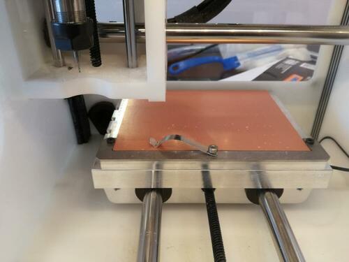
Preparing the PCB milling machine
Placing the PCB
The PCB plate must first be placed in the machine. One important thing: fill the bottom side of the PCB with double-sided adhesive prior to place it in the machine. This will allow the PCB to be fixed.
Calibrating the machine
There are nice wizards for the calibration:
- Homing: just follow the wizards
- Locate tool (measure its size): It will use an electrical contact to know when there is contact. You must make sure that the tool is placed above the metallic part of the plate, so that the electrical contact is good.
- Height of the PCB: This wizard is a little hidden (
bitbreaker→probe material). It uses the same principle, but this time on the PCB. You have to make an electrical contact between the PCB and the plate using the little “jumper”. In this case, the height of material was recalibrated to 1.69 mm.
Configuring the Bantam software
The software has quite a nice interface. You just have to follow the process.
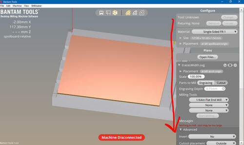
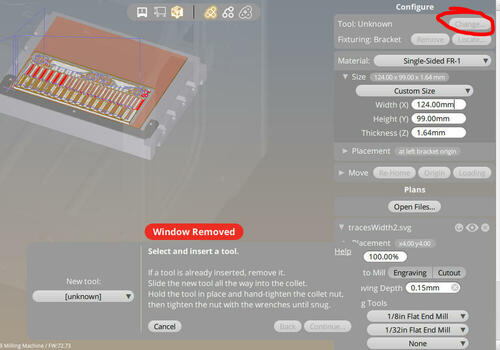
Machine parameters
Here are the parameters used for the support and the machine.
| parameter | Value |
|---|---|
| Material | Single-sided |
| Size | 124.00 mm x 99.00 mm x 1.64 mm |
The move options allow to move the plate. You can bring it close to the opening using the loading button.
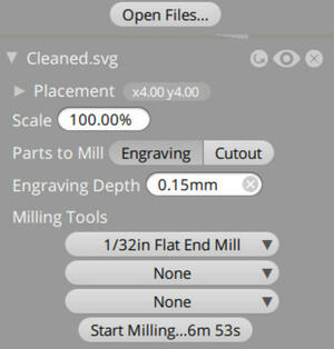
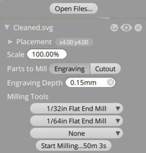
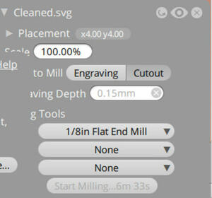
Job parameters
You can then import your svg file. The parameters are quite straightforward.
You can chose up to tree mill to be used for one job. The machine will use them from the smaller to the larger, and you will need to change it during the job.
We decided to do it in three steps to force the machine to use first the middle-sized tool. Be careful for the placement, every drawing must be perfectly superposed! Note that we also tried with the default settings (i.e. from the thinner to the larger mill), and it gave the same result.
| Step 1 | Step 2 | Step 3 |
|---|---|---|
| 1/32in mill | 1/64in mill | 1/8 in mill |
 |
 |
 |
| Rough engraving | Thin engraving | Cutout |
| Full job | Cancel when you should change the tool | full job |
You have to remove the waste (by vacuum) and change tools between each step.
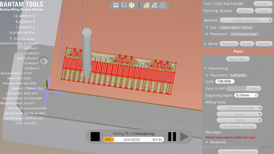
Launching the job
- Changing the tool: You first have to tell the machine you will make the change. Then, simply unlock the tool and place the new one using two wrenches. Be careful that the mill doesn’t fall, it could break!. The wizard will then automatically calibrate the tool height, you just have to make sure that the tool is placed above the metallic part of the plate.
- Let’s go: just press on the “Mill” button, and it starts!
| After step 1 | After step 2 | After step 3 |
|---|---|---|
 |
 |
 |
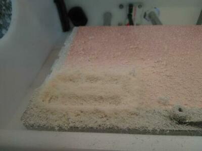
During the milling, you’ll have a lot of waste…, but a nice interface showing in real-time the position of the mill.
Removing the PCBs
- Remove all the waste.
- Remove the prepared PCB. Use the loading button to bring the plate close. Leave the rest of the PCB in place, it will avoid you to redo all the calibration. You can use a screwdriver to remove it easily. Note: keep also the software on and do not remove the previous projects, it will allow to know which part of the PCB has already been used.
- Wash the PCB. Water and soap is good.
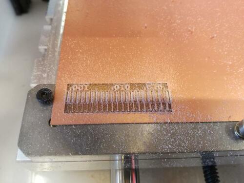
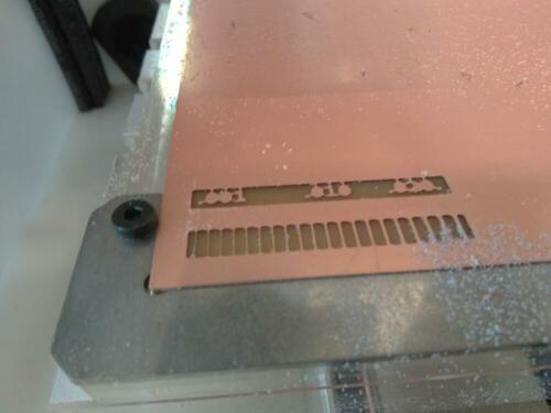
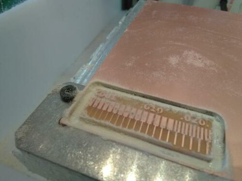
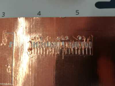
And here is the final result:
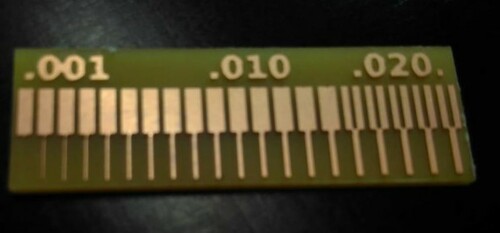
The result is good! It took however a lot of time. Only the thinnest line is gone, and the limit between two lines is around 0.15in.
Another process
We’ve tried another process to make a printed circuit board, using the Silhouette Cameo vinyl cutter.
Facing the same resizing problem as mentioned in the previous test with the milling machine, we first check the effective size of the drawing in Gimp or Inkscape, prior to vectorize the png file, and exporting to DXF format, as this is the only format accepted by our Silhouette printer. This allow us to thwart the resizing done by the Silhouette Studio software, resizing the DXF file to the right size in the Silhouette Studio software prior to send it to the printer.
We first tried to make the ATtiny45 circuit on a vinyl foil. The result is not fully conclusive, as some traces are removed during the transfert process. The settings that we used were: - knife: 1 - speed 5 - force: 10
Still, we decide to test the process with copper foil. The copper foil is a ‘cutronic Foil’, a soft copper self-adhesive foil, supplied with a paper baking, by TechSoft UK Ltd.
We didn’t get the results that we were hoping for, so we decided to test several parameters.
| material | knife | speed | pressure | |
|---|---|---|---|---|
| Test 1 | Vinyl sticker | 1 | 5 | 10 |
| Test2 | Copper (partly) | 3 | 5 | 33 |
| Test 3 | Copper (partly) | 3 | 5 | 25 |
| Test 4 | Copper (partly) | 1 | 5 | 25 |
After these tests we learned that the lines are simply to thin to be able to be cut out, results are terrible, traces are removed during the cutting process whatever parameters values we set.
It occurred to us that maybe, we were cutting to the inside of the traces instead of the outside, and we inverted our image in Inkscape to perform another test.
We got a better result, but not what we wanted.
Later on the day we tried vinyl cutting the same stencil as the milling machine had (the line test), but that didn’t turn out well neither.
For the Silhouette Cameo, wel’ll leave it to this. At home Amy will try with the Brother DX1200 as before she did get good results.
Individual assignment:
Notes and Introduction
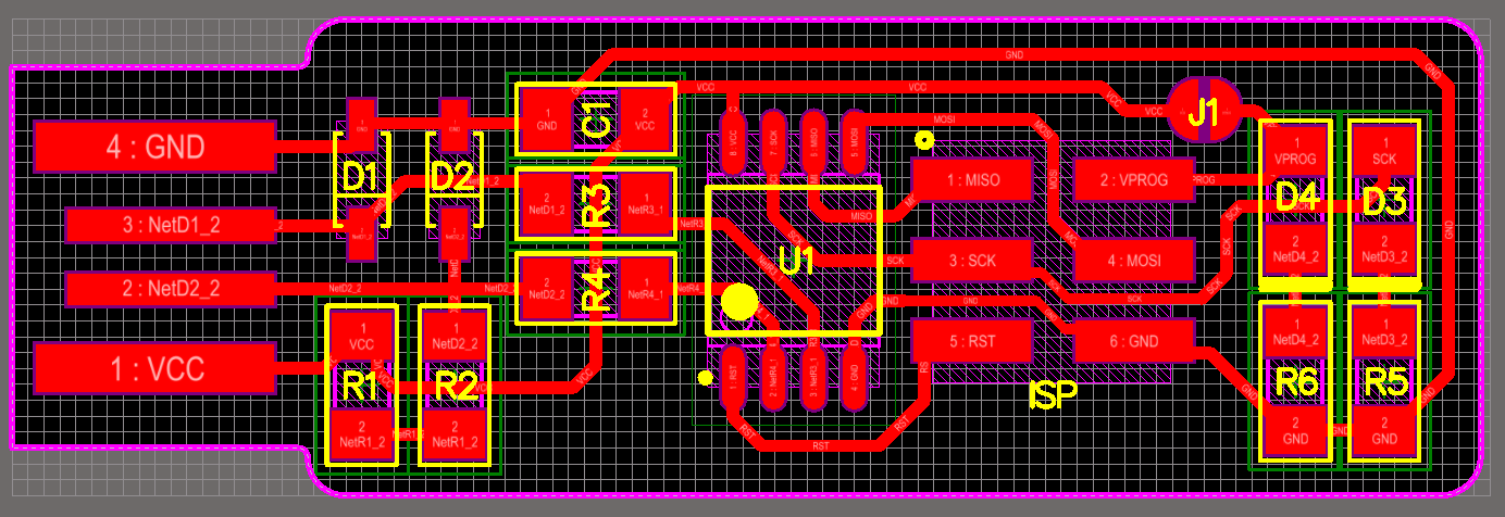
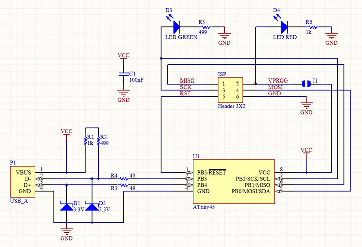
We decided to make the FabtinyISP, following its layout and schematics.
We download the PNG files for the traces and the board outline.
This board, populated with the correct components, is intended to be used as a In-system programmer (ISP), e.g. a system that will allow us to program other programmable logic devices, microcontrollers and other embedded devices as they are, already installed in a complete system on PCB, as long as the correct connector is present on the board!
The BOM (bill of material) for this ISP is the following:
- 1x ATtiny45
- 2x 1kΩ resistors
- 2x 499Ω resistors
- 2x 49Ω resistors
- 2x 3.3v zener diodes
- 1x red LED
- 1x green LED
- 1x 100nF capacitor
- 1x 2x3 pin header
The ATtiny45 is a High Performance, Low Power AVR® 8-Bit Microcontroller with 4K bytes In-System Programmable Flash.
The RED led (D4), connected to the VPROG (VCC) pin of the pin header, is ON when the board is powered by a 5V voltage, resistor R6 is there to limit the current.
The GREEN led (D3), connected to the SCK pin of the pin header, lights up when the programmer is active. Again, the resistor R5 is there to limit the current.
The capacitor C1 ensures the stability of the power supply.
The Zener diodes D1 and D2 ensures stability of the line voltage, by clamping all voltages above 3.3V. The R1+R2 resistors are pull-up resistors to keep the voltage high by default on the line.
R3 and R4 are current limiting resistors.
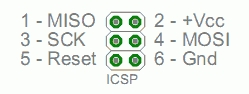
The (serial parallel interface) SPI interface is the interface used to program the microcontrollers; it uses the following 6 pins:
| description | schematic |
|---|---|
|
pin 1 : Master In – Slave Out (MISO) pin 2: VCC (power supply) pin 3 Serial Clock (SCK) pin 4: Master Out – Slave In (MOSI) pin 5: RESET pin 6: GND |
|
Those are available in a consistent physical location on the ICSP header; pin1 is usually marked by a dot or a different pad shape.
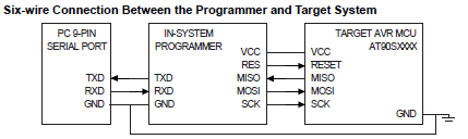
From the application note AVR910:
To ensure proper communication on the three SPI lines, it is necessary to connect ground on the programmer to ground on the target (GND).
To allow programming of targets running at any allowed voltage (2.7 - 6.0V), the programmer can draw power from the target system (VCC). This eliminates the need for a separate power supply for the programmer. Alternatively, the target system can be supplied from the programmer at programming time, eliminating the need to power the target system through its regular power connector for the duration of the programming cycle.
To enter and stay in Serial Programming mode, the AVR microcontroller reset line has to be kept active (low). Also, to perform a Chip Erase, the Reset has to be pulsed to end the Chip Erase cycle. To ease the programming task, it is preferred to let the programmer take control of the target microcontroller reset line to automate this process using a fourth control line (Reset).
For more details, refer to the AVR910: In-System Programming Application Note
PCB fabrication
We made together the milling of the PCB’s to keep the rythm of the group assignment, and followed basically the same process.
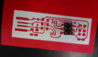
We first made a test on the vinyl cutter to validate the scale of the trace and check that we have all the components.
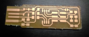
We can then launch the milling of the first PCB! We do the trace in two steps: with the 1/32in and the 1/64in mills.
Since we have the trace and the outline in two png files, we have to do it in two steps with the milling machine. We use a 1/8in mill for the cutout.
Problem: We did not take care and placed the two svg converted images (trace and outline) with the same (x,y) position. Of course, in the process of converting the png to svg, we changed the reference of the images superposition
Solution: We had to manually adjust the position of the outline relatively to the traces. Here are the final shift values:
x : 1.25 mm y : 1.00 mm
Here we have:
Note: Take care of the system requirements for the Bantam milling machine, that runs only on Windows or Mac. For Windows:
- a 64-bit CPU and operating system, Windows 7 minimum
- an Intel Core i3 or equivalent is required, and a Core i5 or equivalent is recommended.
- a graphics driver that provides support for OpenGL 2.1 or higher.
- 4GB of system RAM or higher. 8GB or higher is recommended.
- 100MB of hard drive space is finite
- An USB 2.0 port, nor USB hubs nor extensions, USB cable under six feet long.
Other notes: etching is hazardous, due to the materials used that need to be evacuated in a proper way, so we prefer machining (thanks to a milling machine). Only fiber laser cutting machine is able to make PCB’s, as there is a metal layer…and last but not least, do not use FR4 with milling (glass fibers!!), use FR1 instead.
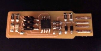
Assembly
Next step is the assembly, e.g. soldering the SMD (surface mounted devices) on the board on the appropriate place, following the circuit schematic.
Mounting the SMD components on the PCB requires attention:
-
be careful to the diodes (LEDS and Zeners) orientation: the cathode is usually marked by a dot, a color line or a gray line on the package
-
be careful to place the ATtiny45 in the proper position (dot on package indicates pin 1)
-
soldering tiny parts requires some skills, and a adequate procedure. What I’ve done here is to bring some solder on a pad first, then solder the component to it, and finally, once the component is properly placed, solder the other pin(s) on the other pad(s).
-
start soldering the tiny parts first ( eg the ATtiny), ending by the biggest (the pin header)
-
to protect the copper surface @USB contacts, the pads are covered with solder, distributing it with the solder iron pen.
Hardware tests
When assembly is completed, check the continuity of the traces, removing excessive solder and shorts or/and improving solder joints quality.
Continuity checks are done by means of a multimeter in ‘continuity check’ position. Diode test are done by means of a multimeter in ‘diode check’ position.
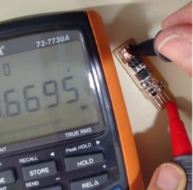
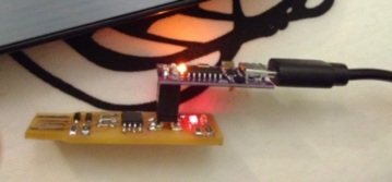
As a test, at applying a 5V voltage between VCC and GND, the RED LED& lights up.
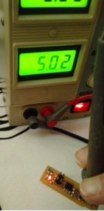
Yeah! Everything seems to be fine…
First software tests
In a first instance, we want to program our ATtiny45 to make the GREEN led blinks.
TEST 1: Programming through ARDUINO IDE
Therefore, we will use the ARDUINO IDE on a Windows 7 OS, and the 5V Micro USB Tiny AVR ISP ATtiny44 USBTinyISP Programmer.
Step 1 : Download and Install
Download ARDUINO IDE from here and follow the procedure for the installation…
ARDUINO Integrated Development Environment (IDE) is a graphical user-interface (GUI) that contains a programming editor and graphical front-ends to all the tools as compiler, assembler, linker, standard C library, and librarian programs that make live of newcomers in programming quite easy. These front-ends consist of dialog boxes which allow you to set build options and a way of creating a list of files that are in a “project”. These graphical front-ends hide and encapsulate the real command-line compiler, assembler, linker, and standard library that are in the background of any software development toolset.
Step 2 : Configure the IDE
On the ARDUINO IDE, we need to let the system know what are the target (ATtiny45) and the programmer (USBTiny ISP). To do this, we have to add ATtiny µcontrollers to ARDUINO IDE boards, as explained in this tutorial:
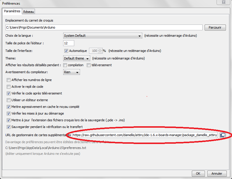
Go to Files→Preferences, find the “Additional Boards Manager URLs” field near the bottom of the dialog, and paste the URL (https://raw.githubusercontent.com/damellis/attiny/ide-1.6.x-boards-manager/package_damellis_attiny_index.json). Then press OK.
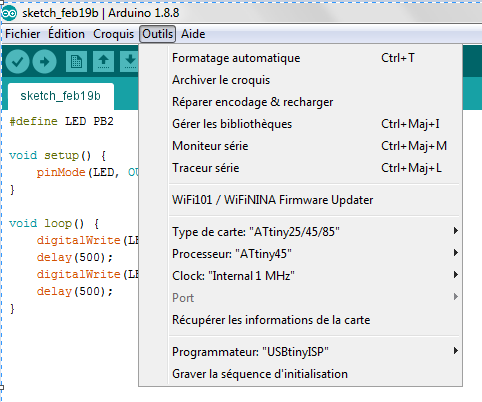
Go to Tools→Board→Boards Manager,You can then choose the correct microcontroller and the correct programmer as well (USBTinyISP).
Take also care to choose the internal clock frequency (by default, it’s 1MHz), not an external one.
After choosing the programmer, we have to ensure that its driver is available on the PC.
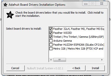
When connecting the programmer to the PC running Windows 7, we can open the Device Manager (Start → Control Panel → System → Device Manager) and check if it is recognized by the system, appearing in the list of devices. If this is not the case, we download the ADAfruit drivers from here, and follow the instructions to download the required drivers (the three first checked boxes)
When this is done, connecting the USBTinyISP to the PC through its USB cable will make it appear in the devices list:
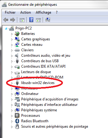
Note: LibUSB-Win32 is a USB library that is used to connect with Atmel ISP programmers, and it includes their drivers.
Be careful to use a correct USB cable, not a cheap one used to power only, as the device will not be recognized when connecting to the PC!!
Connect the USBTinyISP to the target through the ICSP header, taking care of the correct connections on target board (corresponding SPI pins on pin header, as explained above)
Step 2 successful: the RED LED lights up!
Step 3 : Write program and upload it to target
So, we write a simple code in the ARDUINO IDE to flash the ATtiny45 and let the GREEN LED blinks every second:
#define LED PB2

void setup() {
    pinMode(LED, OUTPUT);
}

void loop() {
    digitalWrite(LED, HIGH);
    delay(500);
    digitalWrite(LED, LOW);
    delay(500);
}
In the version 1.8.8. of the ARDUINO IDE used here, we need to specify that we upload to the target through a programmer (Sketch -> Upload Using Programmer) to achieve the programming of our target through a USBtinyISP.
Great, it works fine! Step3 successful! Here is the result:
TEST 2: Programming through WINAVR
Before transforming irreversibly our ATtiny45 into a ISP, let’s go for some tests with other softwares, IDE’s and OS to just program it to have the GREEN led blinking…
First try WinAVR on the same PC with Windows 7 OS, and the 5V Micro USB Tiny AVR ISP ATtiny44 USBTinyISP Programmer.
WinAVR is a suite of executable, open source software development tools for the Atmel AVR series of RISC microprocessors and AVR32 series of microprocessors hosted on the Windows platform.
Here we dive in the details of programming microcontrollers through command lines…
Indeed, WinAVR does not have a complete graphical IDE like ARDUINO. But there is one program that helps making the job hidden behind an IDE: GNU make. The make program reads and interprets a makefile. A makefile is a text file that lists and controls how the software is made.
The WinAVR software development tools include:
- Compilers
- Assembler
- Linker
- Librarian
- File converter
- Other file utilities
- C Library
- Programmer software
- Debugger
- In-Circuit Emulator software
- Editor / IDE
- Many support utilities
STEP 1: Download and Install
Download WinAVR from here. It is a the 2010 version of WinAVR…
Not respecting this rule leads to the following error:
*make: Interrupt/Exception caught (code = 0xc00000fd, addr = 0x4217b3)*
Here’s what appears in the Start menu, once installed:
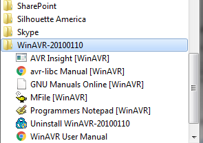
- The Programmers Notepad is an Open Source editor with some IDE features. It allows us to write a program
- Mfile is a automatic makefile generator for AVR GCC. it uses a template of a makefile for WinAVR that we can edit to configure our system and generate our dedicated makefile, based on some simple menu input
- AVR Insight is GNU Debugger (GDB) with a GUI and a console window, for command-line interface. It can be used, with other programs, to simulate or emulate our AVR program.
Do not forget to install the programmer driver…
In this case, the driver for the USBTinyISP programmer has been already installed while working with the ARDUINO IDE…
STEP 2: Create the software
- Create a file with extension*.c where we place our code written in C ( note the differences with the code in Arduino, where the code has been written using typical Arduino subroutines…)
#include <avr/io.h>
/* Include header file with symbolic names for avr family
the actual processor type is specified as a command line flag to the compiler*/

#define F_CPU 1000000 // 1 MHz

#include <util/delay.h>

static void avr_init(void);

int main(void)
{
    avr_init();

    while(1)
  {
    PORTB = (1<<PB2); // Turn LED on
      _delay_ms(500);
      PORTB = (0<<PB2); // Turn LED off
      _delay_ms(500);
    }
}
static void avr_init(void)
{
    // Initialize device here.
  DDRB = (1<<DDB2); // pin2 configured as output (Port B Data Direction Register set to 1)
    return;
}
- Create the makefile through the Mfile utility. Let’s look into details in this Makefile. Be careful to:
define the correct target microcontroller, and processing frequency:
# MCU name
MCU = attiny45
# Processor frequency, if not defined in the C source file
F_CPU = 1000000
define executable format and target filename
# Output format. (can be srec, ihex, binary)
FORMAT = ihex

# Target file name (without extension).
TARGET = Test_ATtiny45
point to the correct C files
# List C source files here.
SRC = $(TARGET).c
choose the right programming hardware and software.
To program our device, let’s use the programavrdude. It can interface with various programmers - and the usbtiny is part of them, since version 5.5 of avrdude ( we have version 5.10) - and AVR microprocessors, e.g. the ATtiny45....
We check this by typing the commandavrdude -c ?in a cmd windows…
#---------------- Programming Options (avrdude)
# Programming hardware
AVRDUDE_PROGRAMMER = usbtiny

# com1 = serial port. Use lpt1 to connect to parallel port.
AVRDUDE_PORT = usb

AVRDUDE_WRITE_FLASH = -U flash:w:$(TARGET).hex

# Define programs and commands.
SHELL = sh
CC = avr-gcc
OBJCOPY = avr-objcopy
OBJDUMP = avr-objdump
SIZE = avr-size
AR = avr-ar rcs
NM = avr-nm
AVRDUDE = avrdude
REMOVE = rm -f
REMOVEDIR = rm -rf
COPY = cp
WINSHELL = cmd

# Program the device.
program: $(TARGET).hex $(TARGET).eep
$(AVRDUDE) $(AVRDUDE_FLAGS) $(AVRDUDE_WRITE_FLASH) $(AVRDUDE_WRITE_EEPROM)
Other lines in the Makefile give info on compiler, libraries, linker, flags, etc…
STEP 3: Run the software and program the device
First, let’s use the Notepad Programmer.
-
Create a new project and add the two files described above (Test_ATtiny45.c and the Makefile)
-
run a
Tools → make all
This launches a compilation of Test_ATtiny45.c…:
avr-gcc -c -mmcu=attiny45 -I. -gstabs -DF_CPU=1000000UL -Os -funsigned-char -funsigned-bitfields -fpack-struct -fshort-enums -Wall -Wstrict-prototypes -Wa,-adhlns=./Test_ATtiny45.lst -std=gnu99 -MMD -MP -MF .dep/Test_ATtiny45.o.d Test_ATtiny45.c -o Test_ATtiny45.o
…followed by a linking process of Test_ATtiny45.elf…:
avr-gcc -mmcu=attiny45 -I. -gstabs -DF_CPU=1000000UL -Os -funsigned-char -funsigned-bitfields -fpack-struct -fshort-enums -Wall -Wstrict-prototypes -Wa,-adhlns=Test_ATtiny45.o -std=gnu99 -MMD -MP -MF .dep/Test_ATtiny45.elf.d Test_ATtiny45.o --output Test_ATtiny45.elf -Wl,-Map=Test_ATtiny45.map,--cref -lm
…and a executable file to be loaded onto the target flash memory, Test_ATtiny45.hex:
avr-objcopy -O ihex -R .eeprom -R .fuse -R .lock Test_ATtiny45.elf Test_ATtiny45.hex
To program the target with the executable code, through the USBTinyISP, is done by using the command make program. This launches the programming
avrdude -p attiny45 -P usb -c usbtiny -U flash:w:Test_ATtiny45.hex
This checks if the programmer and target are connected, launches a flash erasing cycle, a writing cycle and finally a verification of the programming process.
Programming of the ATtiny45 done!
TEST 3: Making a programmer out of the ATtiny45 PCBs
We can now load our source code to program our PCB as a programmer.
Therefore, we first download the firmware source code
In a similar way to previous test, we create a project in Programmer’s Notepad with provided files (main.c and Makefile). Be careful to check, in the Makefile, if the target microcontroller and the programmer are properly defined.
In WInAVR, we can add new make commands in Tools → Options to reflect the needed operations…
We first run make. This builds the fts_firmaware.hex file that will get programmed onto the ATtiny45.
We then run make flash. This erases the target chip, and program its flash memory with the contents of the .hex just built before.
In a second stage, it is necessary to set the configuration fuses, in two steps:
First, we’ll set the fuses that control where the microcontroller gets its clock source from. (The USB requires the clock to come from the PLL, and not be divided by 8). This will allow us to check that the board works as a USB device, but it won’t yet be able to program other boards.
Run make fuses. This will set up all of the fuses except the one that disables the reset pin.
Check the USB functionality now: Unplug the target PCB and the programmer from the USB port, then plug the target PCB only to the USB. It should be recognized by the PC, and appear in the Devices manager list.
Only after confirming that USB works, we’ll set the fuse that disables the reset pin and turns it into a regular GPIO pin. This will let the chip use the reset pin to program other boards, but will disable the ability for this chip to be programmed again.
Connect the ISP programmer to your board one more time, and run make rstdisbl. This does the same thing as the make fuses command, but this time it’s going to include that reset disable bit as well.
And finally, we disconnect VCC from the Vprog pin on the ISP header by removing the bridge on the solder jumper. Doing this will impeach our ICSPprogrammer to power the target it will be connected to…(power supply from an external source is then needed for the target!!)
Our PCB is ready to be used as a programmer!!
Still to do if I had time....
Nothing more to do here, let’s see the next assignments!