10. Molding and casting
Assignment
-
[x] group assignment: review the safety datasheets for each of the molding and casting materials, then make and compare test casts with each of them
-
[x] individual assignment: design a 3D mold around the stock and tooling that you’ll be using, mill it, and use it to cast parts
Summary
This week, I * designed a mold requiring to use Fusion360, so i finally learn to work with it… * made a mold, so I finally learned to work with the Kinetic CNC machine… * tried several combinations of mold/piece materials
Files are available here(cube) and here(Fablogo)
Group assignment
Choice of materials
We decided to work with different materials available @FablabULB, of different kinds:
* silicones - to make flexible molds
* epoxies - to make models and final pieces
* plaster - to make rigid moldings
* polyurethane
Dental Silicone (vinylpolysiloxane (addition silicone)):
Looking at the datasheets of the several products available here, we see that the Elite Double range of silicone consists of several coloured products, final hardnesses (4) and setting times (3). Compatible with stones, polyurethane resins, acrylic resins and phosphate and alcohol-based investments (note: a dental casting investment is a material applied as a soft paste to a pattern that hardens to form a mold for casting)
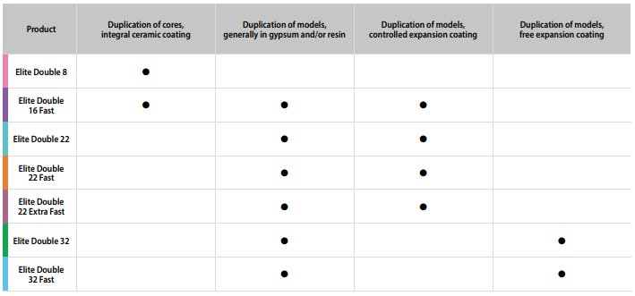
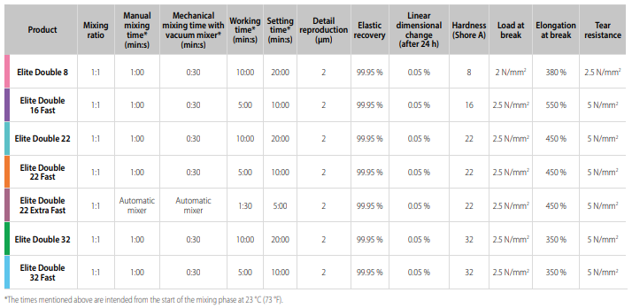
Our choice: Elite Double 32, Silicone, 32 A (Zhermack). It is a good compromise between manual mixing time (1min), working time (10min) and setting time (20min), at room temperature, to be used with materials with free expansion casting
Instructions for use: 1. Measure or weight equal amounts of Catalyst (white) and Base (coloured) in a graduated container. 2. Mix the two components well, until colour is even. 3. slowly pour Elite Double, preferably from a height of about 30cm above the flask. If the quantity measured out is not sufficient to complete the process,wait until the silicone has hardened completely and then add more material the same way.
Safety requirements:
There is no specific safety document available on internet!!
So the minimum requirements is definitely to wear gloves when handling these chemicals.
PDMS (polydimethylsiloxane)
Sylgard 184, a Dow Corning Corporation (now DOWSIL) product, is a silicone elastomer (PDMS) kit. The kit contains two chemicals: Base (part A) and Curing Agent (part B), that are mixed in 10:1 mass ratio. Both the chemicals are transparent, but quite viscous in nature (mixed material viscosity is 3500 cP).
At room temperature, Working time is approximately 1.5 hours and full cure will take 48 hours to achieve optimal performance.
Heat cure time at 100° Celsius is 35 minutes, at 125° Celsius is 20 minutes and at 150° Celsius is 10 minutes.
Sylgard is designed to cure into a flexible elastomer that is well suited for the protection of electronic applications.
Safety requirements
Please don’t use pipettes to draw the chemicals as they are pretty thick. Also, wear gloves when handling these chemicals.
SuperSap CLV Bio-epoxy
From the reseller page: SuperSap CLV is a special formulation of the highly regarded SuperSap resin system from Entropy Resins. SuperSap CLV has been formulated to provide a clear, low viscosity bio-derived epoxy resin that is suitable for both hand laminating and vacuum resin infusion.
Instructions for use
No special document available, but the proportions epoxy/hardener are indicated on the recipient: 100/40. As for other materials, we need to mix well the components before pouring from a certain height to degas the material if we don’t use degassing chamber.
As stated in reseller site, pot life is estimated to be about 30mins and a cure time of around 12hrs at room temperature.
Safety requirements
Available here
Xencast PX90 Polyurethane
From the reseller page: Xencast® PX90 is an industry leading semi-flexible polyurethane casting resin which cures to a firm yet still slightly flexible 90 Shore A hardness whilst retaining unbeatable abrasion resistance and resilience.
Xencast® PX90 is ideal for product applications requiring a semi-flexible yet highly durable material including hand tools, skateboard wheels, engine bushes, props and training weapons.
At room temperature, working time/pot life (5min) and setting time (7 days), at room temperature, to be used with materials with free expansion casting
Safety requirements
Available here
Smooth-on silicones
Ecoflex 0035 fast and Ecoflex 0030 are very similar, excepted that the first one cures in 30 minutes while the second cures in 1 hour! Their specificity is their extreme softness and large deformations capabilities (up to 900 %).
Mold Star 16 FAST are easy to use platinum silicones mixed 1:1 by volume, with a 6 minutes pot life and 30 minutes cure time.
Safety requirements
Available here, those product are certified skin-safe!
Plaster
Christophe also used usual construction material plaster for his tests!
Safety gloves:
Why use Nitrile gloves and not latex? When working with epoxy resin premium quality tough Nitrile gloves should always be used instead of latex because latex gloves can allow the transport of harmful amines through the gloves. These tough Nitrile gloves block these amines which is why they should always be used when working with epoxy resin.
Mold shape
Axel and Greta made 2 different types of moulds to test different materials.
Axel’s molds
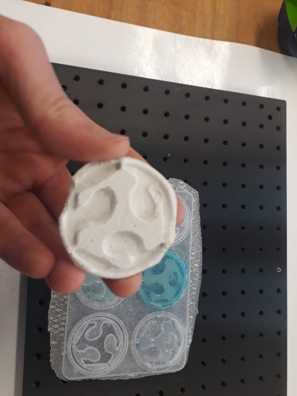
I wanted to make a mold that can be used to cast 6 identic coins (for up to 6 differents materials). I choosed to use the Fablab logo, so I searched for a .svg drawing and I found it in this Thingiverse files. Then I imported the .svg into Easel, I added a larger circle (for deeper outline cut), then I added 5 copies. Finally, I added a rectangle for the bottom of the mould. This is how it looks like in Easel :
- Light grey (logo) is 2mm deep.
- Medium grey (rectangle) is 4mm deep.
- Dark grey is 6mm deep.
Here is the link for the g-code files. There is the original logo and 3 g-code files :
- Fablab_single.nc that is meant to be milled with a single 1/8” end mill.
- FabLab_roughing.nc to make a rough milling with a 1/8” end mill (before the detail pass).
- FabLab_detail.nc to make a clean milling with a 1/16” end mill (after the roughing pass).
This is the simulated toolpath for the single pass version :

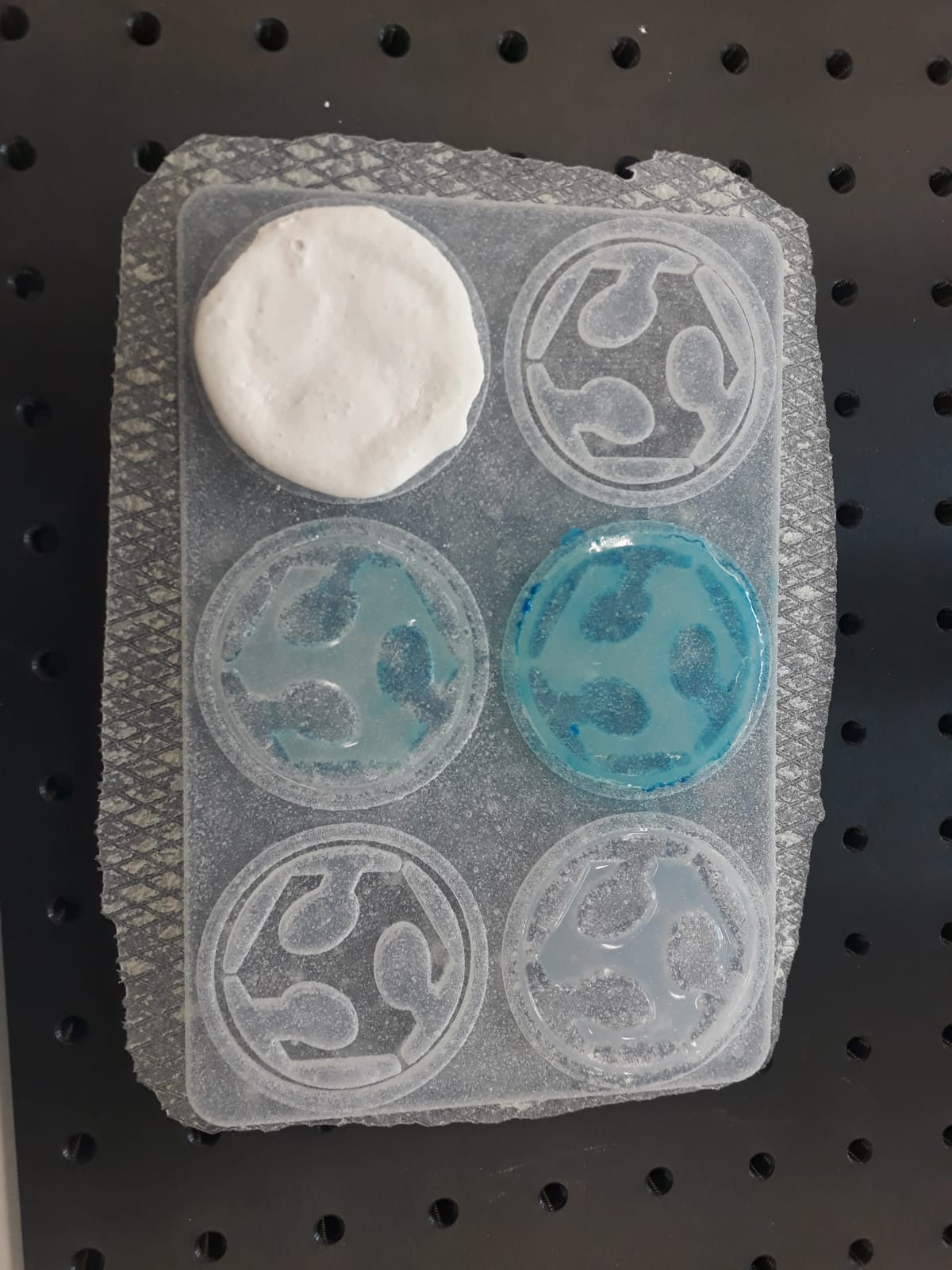
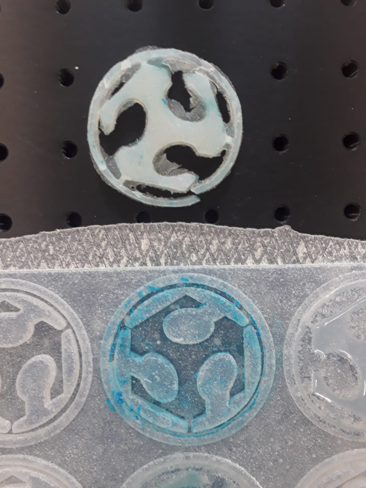
From the milled positive a silicone negative using AS40 is moulded, to be used as effective mold!
Greta’s molds
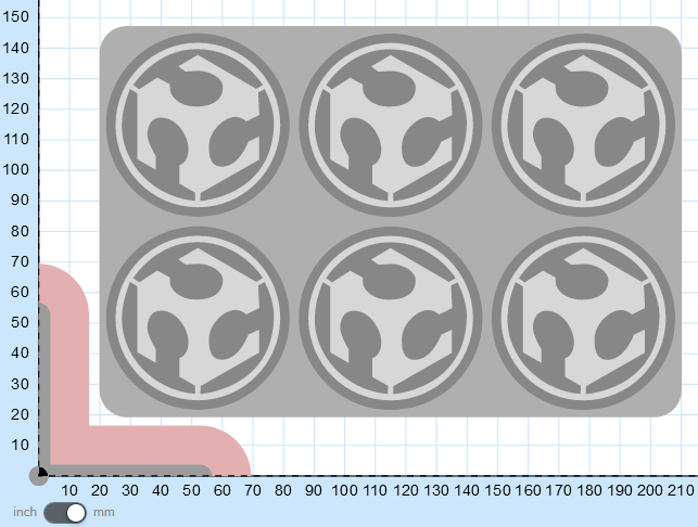
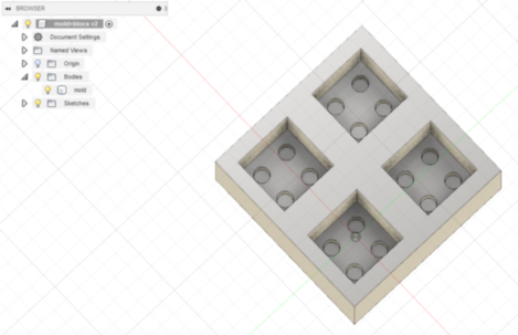
Concerning the shape to form, we opted for a simple structure, that we create with Fusion360 (on Windows7). The idea is to compare the behaviour of those materials, not to make a real mold yet. In order to test all materials at the same time, we decided to go for a unique mold with four cavities, in which we will pour the materials.
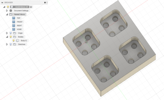
Of course, this model needs some revision to take manufacturability into account; sharp corners aren’t acceptable for the CNC machine… So here is the new version:
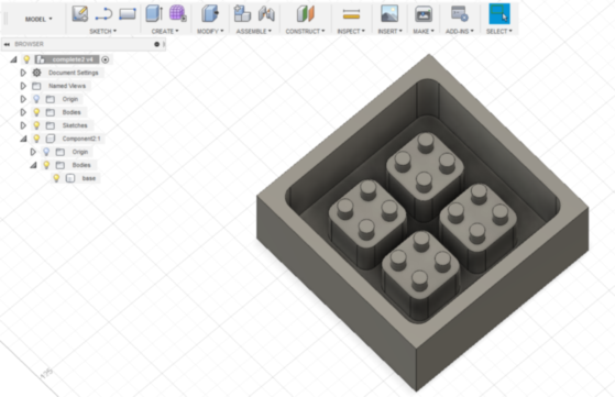
This mold can be used to make the cubes directly by pouring the material into the cavities.
To make a mold, we need to use following structure:
Here is the link for the files for both molds. We use polyurethane foam to mill our molds.
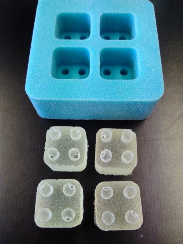
From the milled positive, a silicone negative using Mold Star 16 FAST is molded, to be used as effective mold. As explained above, in the materials choice section, we made by hand a 1:1 volume ration of both components, and pour the mixture in the mold, within the six minutes pot life time, wearing golves and protection lab suit.... We didn’t use any release agent, and effectively, foam and rubber didn’t adhere, but the shape obliged us to break the foam:
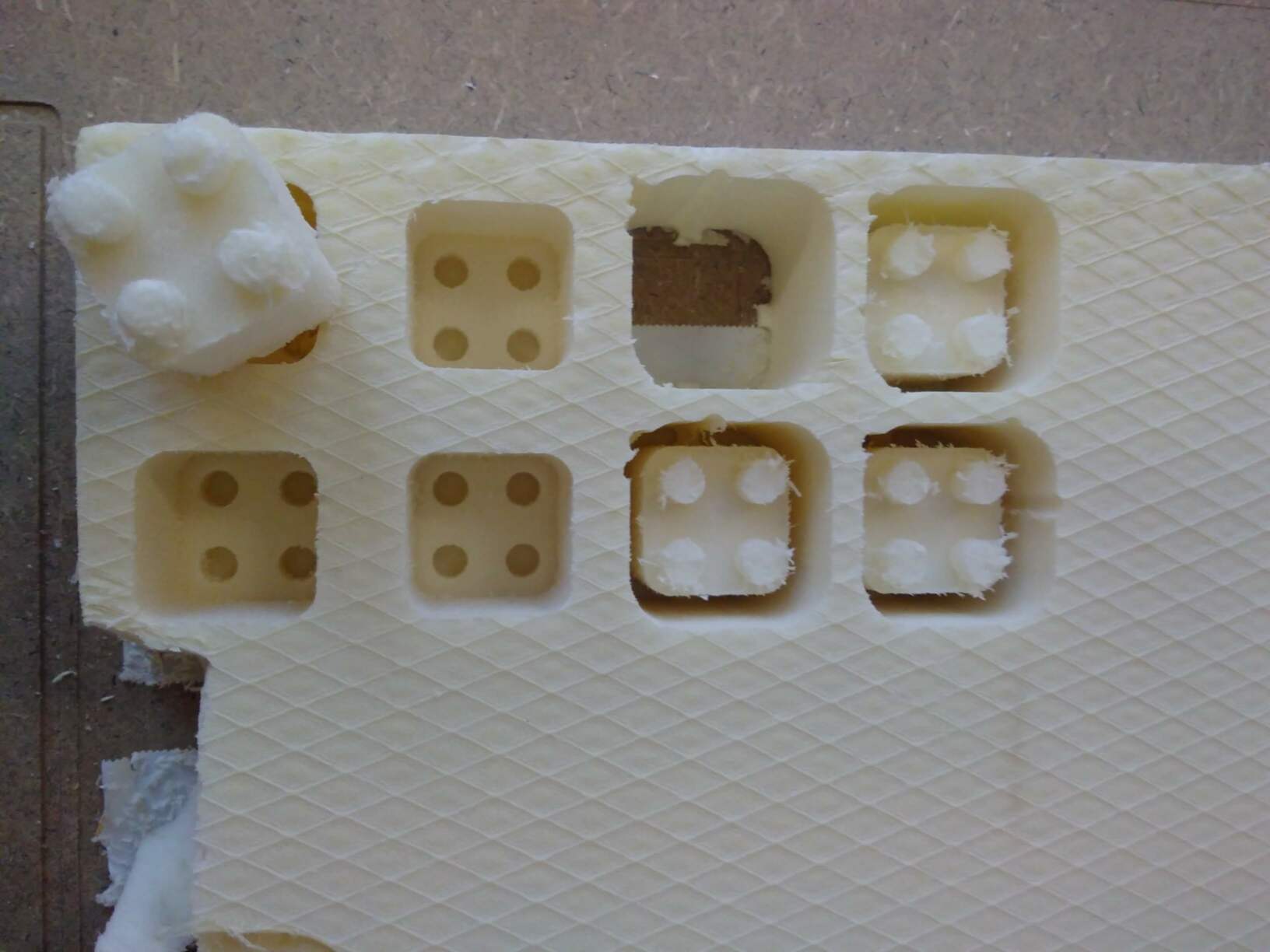
Molding results
Axel’s mold and Plaster
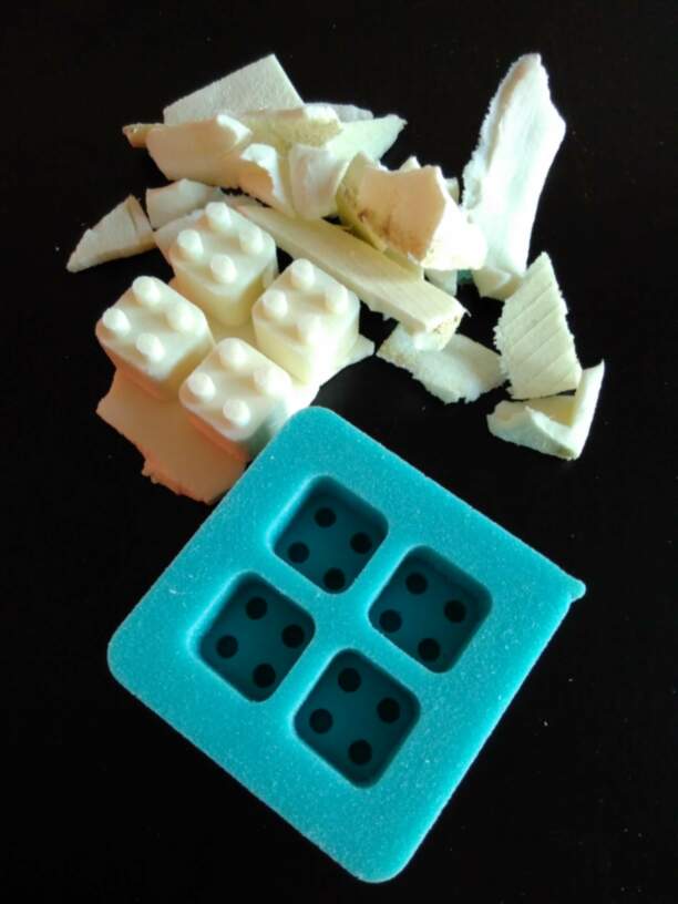
The demolding was easy but the plaster broke, probably because it was not dry enough. Silicone was good for the mold.
Axel’s mold and Ecoflex
We made three tests, one using a demolding agent](https://www.easycomposites.co.uk/#!/wax-and-mould-release-agents/PVA-mould-release-agent.html) and the others without. We first tried to unmold the one with demolding agent, supposed to be easier. Indeed, the release agent helped, but this remained very difficult, seeing the adhesion between the two silicone!
Seeing the difficulty and the bad results for the first one, the two others without release agent were not even tried to demold!
Greta’s polyurethane mold and Epoxy
We made it the wild way, just to evaluate the results: no degassing of the epoxy, no release agent.... SuperSap CLV Bio-epoxy, is mixed by hand in a 100:40 ratio in volume with its hardener as explained in the materials choice section (http://fab.academany.org/2019/labs/ulb/students/greta-vanvinckenroy/assignments/week10/#supersap-clv-bio-epoxy), again with the adequate clothing to avoid incidents: gloves and lab suit…
The result - the day after…-, as expected, is quite disastrous: the epoxy attacks the foam if not adhering to the mold, the epoxy piece is full of bubbles, the piece surface is rough:
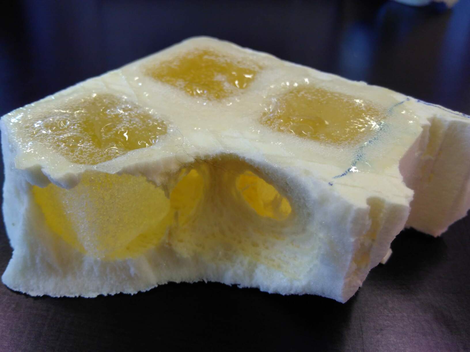

Conclusion: combination of materials not to be used!
Greta’s rubber mold and Epoxy
Again, we made it the wild way: no degassing of the epoxy, no release agent .... at the same moment and same conditions.
The result, is better: the epoxy piece is easily removed from the mold although there was no release agent, the epoxy piece has still but less bubbles, the piece surface is still rough, but acceptable.
The dimensions of the pieces are also acceptable: 19.95mm to 20.05mm for the cube side, 5.06mm for the protrusions diameter!
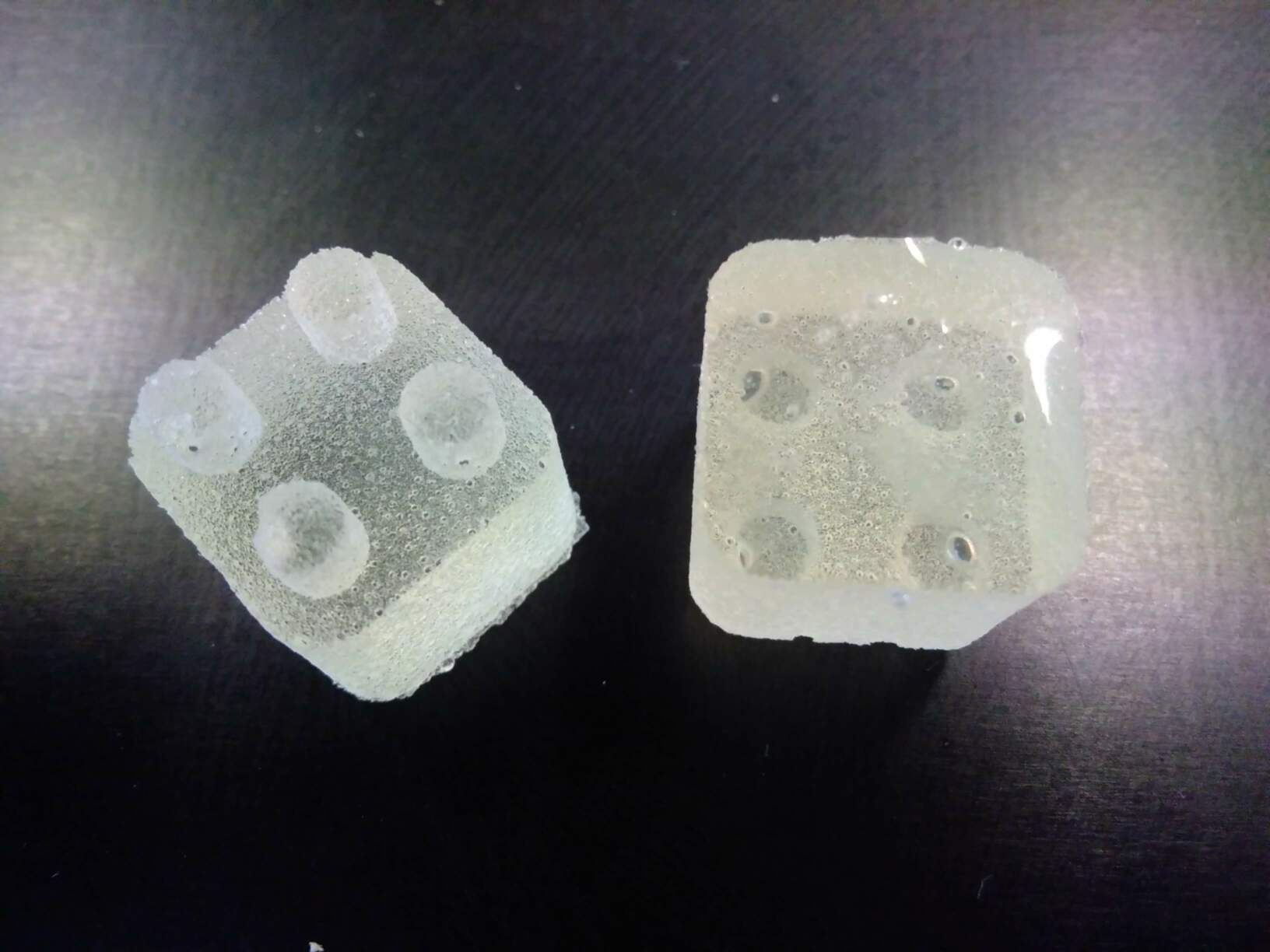
Conclusion: this combination of materials is fine, but the epoxy needs to be degassed after mixing with hardener and prior to pouring in the mold!
Safety gloves:
Why use Nitrile gloves and not latex? When working with epoxy resin premium quality tough Nitrile gloves should always be used instead of latex because latex gloves can allow the transport of harmful amines through the gloves. These tough Nitrile gloves block these amines which is why they should always be used when working with epoxy resin.
Individual assignment
As I didn’t have the time yet to use the Kinetic CNC machine, I made use of the group project to learn working with it, as well as with the software Fusion360…
Here are the pieces:
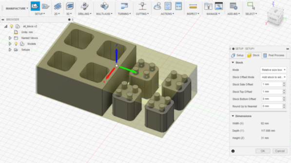
Start point is four small blocks of 20x20mm with four circular protrusions of 5mm diameter and 5mm height on top.
Let’s mill both positive and negative mold:
Milling configuration in Fusion360
After creation of model in the MODEL section of Fusion360, we need to go to the MANUFACTURE section.
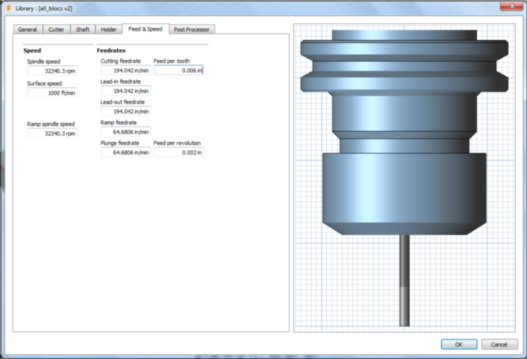
Let’s create a SETUP, choosing the correct tool, with the help of the Fablab Feeds and Speeds calculator: the physical data for the milling tool are measured (diameter, flute length, etc…) as shown below (tab cutter), and the feeds and speeds data are calculated in tab Feeds and Speeds.
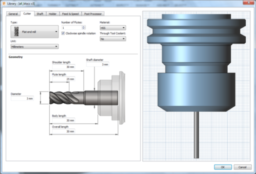
Remark: we use here flat end mill, for plane or rough curved surfacing. Should we have 2D5 surfaces, we’d better use round nose mill for the finishing passes....’
In the 2D tab, we choose different milling techniques to achieve the desired structure.
For one block:
-
FACE:
GEOMETRY: we define the side of the cube as the stock
HEIGHTS are given as follows:- bottom: select the top surface of the protrusion
- top: from stock top
- feed: offset of 5mm from top height
- retract: 5mm from stock top
- clearance: 10mm from retract height PASSES to shape the face follow these rules:
- tolerance: 0.01mm
- stepover: 2.85mm
- multiple depth with a maximum stepdown of 1.5mm
-
2D ADAPTATIVE CLEARING(first pass):
GEOMETRY: we define the five contours defining “the pocket” (external square + four protrusions)
HEIGHTS are given as follows:- bottom: select the top surface of the cube
- feed: offset of 5mm from top height
- retract: 5mm from stock top
- clearance: 10mm from retract height PASSES to shape the face follow these rules:
- tolerance: 0.01mm
- minimum cutting radius: 0.3mm
- use slot clearing of 3.75mm ( to force the milling tool to stay in the center and complete the job with a second adaptative pass)
- Multiple Depths with a stepdown of 1.5mm
- No stock to leave, no Smoothing, no Optimizations
-
2D ADAPTATIVE CLEARING(second pass): GEOMETRY: we define the four contours defining “the pocket” (four protrusions) and the stock being the cube profile HEIGHTS are given as follows:- bottom: select the materal side of the cube to define the bottom??!!
- top: select the top surface of the stock
- feed: offset of 5mm from top height
- retract: 5mm from stock top
- clearance: 10mm from retract height PASSES:
- tolerance: 0.01mm
- minimum cutting radius: 0.3mm
- use slot learing of 3.75mm ( TO DO IT IN TWO PASSES, completing with a second adaptative setup)
- Multiple Depths with a stepdown of 1.5mm
- No stock to leave, no Smoothing, no Optimizations
-
2D CONTOURGEOMETRY: we define the contour (rounded square) to be cut, without he need of a stock contours, and creation of tabs to support the piece while reaching the end of the milling. HEIGHTS are given as follows:- bottom: stock bottom with an offset of -0.2mm
- top: select the top surface of the cube
- feed: offset of 5mm from top height
- retract: 5mm from stock top
- clearance: 10mm from retract height PASSES
- Multiple Depths with a stepdown of 1.5mm (rough) and 0.2mm (finishing)
- No stock to leave, no Smoothing, no Optimizations
We then generate the toolpath and simulate the complete milling process through (ACTIONS → Simulate). Once the simulation is correct, we can duplicate the process for the four blocks, and run the complete simulation again for final check.
When simulation is OK, we can generate the Gcode file (ACTIONS → Post Process), e.g. convert the machine independent cutter location data into machine-specific NC code. Therefore, we need to load the Kinetic postprocessing configuration file into Fusion360 (file kinetic-nc.ps) to be found on the controlling PC of the CNC.
Milling Configuration on Kinetic CNC machine
On the controlling PC, we need to configure the CNC prior to launch the milling Process
Jog setup
Zeroting the machine in X Y: click on go to park position, take care to be be in G54 workpiece offset mode (right panel), move the milling head above the corner of the stock (by means of the left panel with arrows, controlling the speed from continuous to steps of 0.01mm)
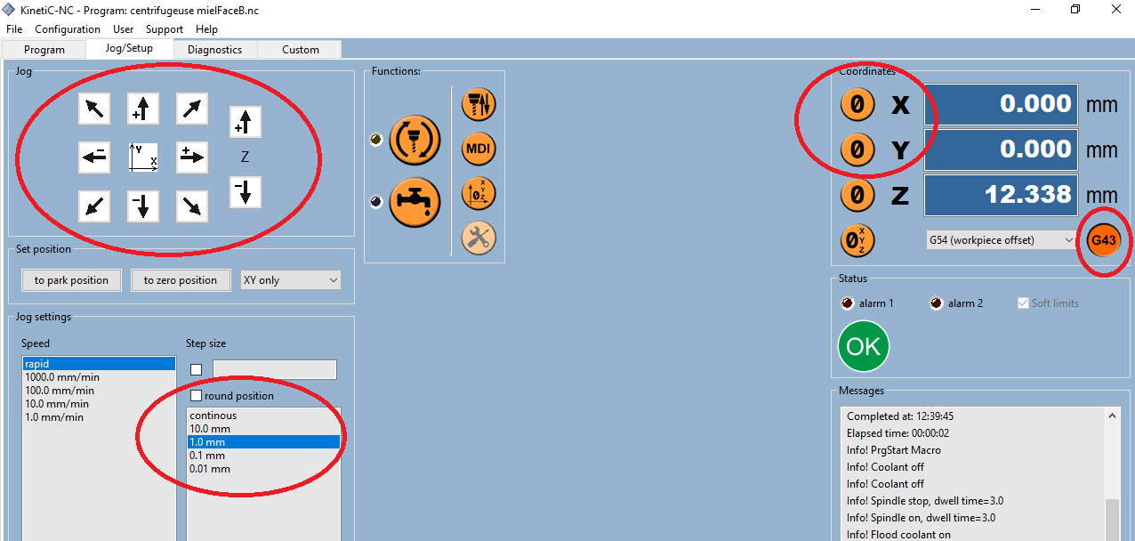
Once the position is correct, click on the “0” button in the right coordinates panel.
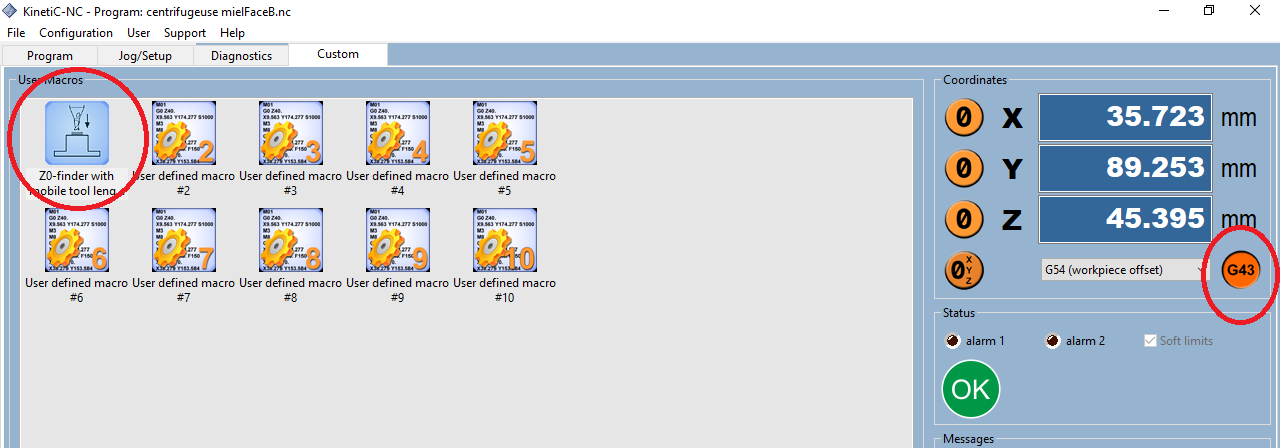
Custom
To zero the machine in Z, we use the mobile button sensor that we place under the milling head, and we launch the tool Zero finder.... No other operation is needed afterwards: the Z-zero is fixed at stock top.
Take care to have the G43 button activated in the coordinates panel.
Milling the piece
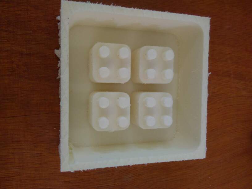
Here are the first pictures of the molds made of isolation polyurethane foam:
The rest of the process is developped in the group assignment!
Still to do if I had time....
I’d like to start the fabrication of an epoxy box to seal the PCB I’ll use in my final project....