12. Output devices
Assignment
-
[x ] individual assignment: add an output device to a microcontroller board you’ve designed, and program it to do something
-
[ ] group assignment: measure the power consumption of an output device
Summary
This week, I wrote a simple program to have a NEMA 17 stepper motor functioning through an A4988 driver....
Design files are available here
Individual assignment
Thinking in my final project, I would like to use actuators as motors to move the panels. Other devices as LCD screens and light actuators would be necessary Bluetooth communication will be the subject of following weeks…
Stepper motor: an introduction
How does a stepper motor work?
A nice explanation can be found in the wikipedia page.
A stepper motor, also known as step motor or stepping motor, is a brushless DC electric motor that divides a full rotation into a number of equal steps. The motor’s position can then be commanded to move and hold at one of these steps without any position sensor for feedback (an open-loop controller), as long as the motor is carefully sized to the application in respect to torque and speed.
Bipolar motors, like the one I intend to use, have a single winding per phase. The current in a winding needs to be reversed in order to reverse a magnetic pole, and the driver chip will make the job for us…
A typical driving pattern for a two coil bipolar stepper motor would be:
- step 1: drive coil A with positive current; drive coil B with positive current
- step 2: drive coil A with positive current; drive coil B with negative current
- step 3: drive coil A with negative current; drive coil B with negative current
- step 4: drive coil A with negative current; drive coil B with positive current
The cycle is complete and begins anew.
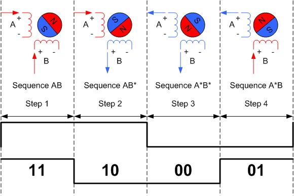
To turn in the other direction, sequences 2 and 4 are swapped as follows:
- step 1: drive coil A with positive current; drive coil B with positive current
- step 2: drive coil A with negative current; drive coil B with positive current
- step 3: drive coil A with negative current; drive coil B with negative current
- step 4: drive coil A with positive current; drive coil B with negative current
I’ll use here a NEMA 17 type stepper motor, 1.8°, ~0.4Nm, 4 Wires
Two models are available:
- OSM Bipolar Stepper Motor 1.8°, 0.40Nm, 12 V dc, 1 A, 4 Wires (ref 17HS15-0404S)
coil 1: black A - green C
coil 2: red B - blue D
coil 1: black A - red C
coil 2: green B - blue D
During tests, connecting the motor in this order doesn't make the motor turn. Measuring the impedance between a pair of wires between the four show that there is a low impedance between black and green wires, and between red and blue!!! Other combinations give open circuit value... And indeed, with the correct connections, the motor turns!!
- Sanyo Denki Bipolar Stepper Motor 1.8°, 0.39Nm, 24 V dc, 1 A, 4 Wires (ref 103H5208-5210),
coil 1: orange A - blue C
coil 2: red B - yellow D
A motor driver is required to control the stepper motor from the microcontroller to ensure the proper functioning of the motor that requires more power than the one delivered by a microcontroller. Protection of the microcontroller against current spikes is also ensured by the motor driver.
Motor driver A4988
The A4988 microstepping motor driver is designed to drive bipolar stepper motors in full-, half-, quarter-, eight-, and sixteenth-step modes. No phase sequence tables are required for operating the driver – a single pulse through the STEP input drives the motor one micro-step.
The micro-stepping resolution truth table is provided in the datasheet of the A4988:
| MS1 | MS2 | MS3 | Microstep Resolution | Excitation Mode |
|---|---|---|---|---|
| L | L | L | Full Step | 2 Phase |
| H | L | L | Half Step | 1-2 Phase |
| L | H | L | Quarter Step | W1-2 Phase |
| H | H | L | Eighth Step | 2W1-2 Phase |
| H | H | H | Sixteenth Step | 4W1-2 Phase |
The DIR pin is for determining the direction of rotation of the motor.
At each step, the current for each full-bridge is set by the value of its external current sense resistor (RS1, connected to pin SENSE1 and RS2, connected to pin SENSE2), a reference voltage (VREF, connected to pin REF and taken as VCC), and the output voltage of its DAC (which in turn is controlled by the output of the translator).
Internal PWM Current Control. Each full-bridge is controlled by a fixed off-time PWM current control circuit that limits the load current to a desired value, ITRIP. The internal PWM current control circuitry uses a one-shot circuit to control the duration of time that the DMOS FETs remain off. The off-time, tOFF, is determined by the ROSC terminal.The ROSC pin being tied directly to ground, the off-time is internally set to 30 μs; current decay is set to Mixed for both increasing and decreasing currents for all step modes.
Charge Pump (CP1 and CP2). The charge pump is used to generate a gate supply greater than that of VBB for driving the source-side FET gates. A 0.1 μF ceramic capacitor should be connected between CP1 and CP2. In addition, a 0.1 μF ceramic capacitor is required between VCP and VBB, to act as a reservoir for operating the high-side FET gates.
VREG. This internally generated voltage is used to operate the sink-side FET outputs. The nominal output voltage of the VREG terminal is 7 V. The VREG pin must be decoupled with a 0.22 μF ceramic capacitor to ground. VREG is internally monitored. In the case of a fault condition, the FET outputs of the A4988 are disabled.
VDD is the logic supply voltage, connected to VCC
A4988 assembled boards
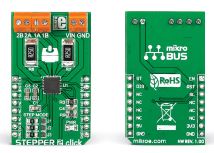
As the A4988 package is a 28-contact QFN with exposed thermal pad, which is hard to solder, I’ll use assembled modules:
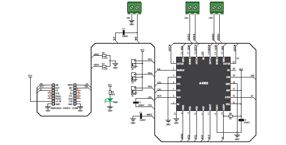
- a the Stepper 2 click from Mikroelektronika, whose schematic is illustrated below:
|
- or the ARD-CNC-Kit1, an Arduino UNO shield that can hold up to four driver motor A4988 microstepping motor driver:
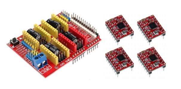
Schematic of the board is given here
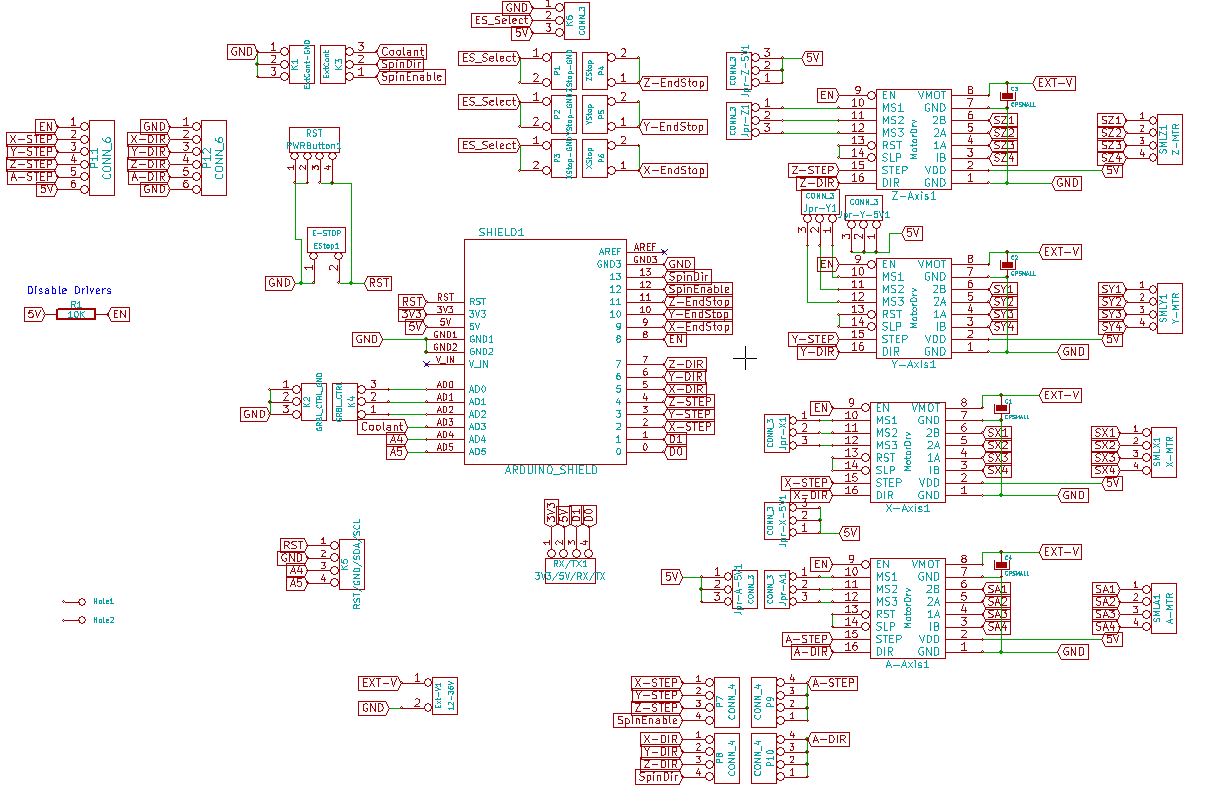
Detailed information can be found on the Protoneer blog
Stepper motor: practical tests
First test with an Arduino UNO board, ARD-CNC-kit1 and OSM stepper motor
We plug the ARD-CNC shield on the Arduino UNO,taking care of its orientation on the UNO.
The connections made through the pinheaders of the shield are as follows:
| shield pin name | UNO pin # | pin description | shield pin name | UNO pin # | pin description |
|---|---|---|---|---|---|
| no name, NC | AREF | not used | RESET | RESET | Reset the UNO and all motor drivers |
| no name | GND | GND | 3.3V | 3.3V | 3.3V on shield |
| SPINDLE-DIR | 13 | Spindle direction on shield | 5V | 5V | logic power supply |
| SPINDLE-EN | 12 | Spindle enable on shield | no name | GND | GND |
| Z_LIM | 11 | Z limits NO switch | no name | GND | GND |
| Y_LIM | 10 | Y limits NO switch | no name, NC | VIN | not used |
| X_LIM | 9 | X limits NO switch | – | ||
| EN | 8 | Enable pin for all stepper outputs | – | ||
| Z_DIR | 7 | Direction-Pin for Z-axis | – | ||
| Y_DIR | 6 | Direction-Pin for Y-axis | – | ||
| X_DIR | 5 | Direction-Pin for X-axis | ABORT | A0 | External GRBL Command Pin for Abort |
| Z_STEP | 4 | Step-Pin for Z-axis | HOLD | A1 | External GRBL Command Pin for Hold |
| Y_STEP | 3 | Step-Pin for Y-axis | RESUME | A2 | External GRBL Command Pin for Resume |
| X_STEP | 2 | Step-Pin for X-axis | COOLANT | A3 | Coolant control |
| TX | TX | TX on shield | A4 | A4 | SCL on shield |
| RX | RX | RX on shield | A5 | A5 | SDA on shield |
The following image displays the functionality of the Arduino pins as used by GRBL (free software for controlling the motion of machines that make things):
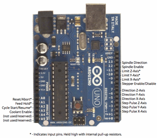
Some pins are useful for the motor control, additional controls and other are just made accessible from the shield for other usages.
Additional pinheaders on the shield are documented on the Protoneer blog
Pins indicated in bold are the ones used in this specific test, in addition to the logic supply.
We apply 0 and 12VDC on the screw-terminals for power supply.
We connect the OSM stepper motor. Looking at wiring diagram in the stepper motor spec (well, not really ;-( ), we can find the correct connections to make:
Go-tronic stepper motor 17HS15-0404S:
coil 1: green (OUT1A) - black (OUT1B)
coil 2: blue (OUT2A)- red (OUT2B)
Make sure the board is set to the Arduino UNO in the Tool->Board menu and the serial port is selected correctly in Tool->Serial Port.
The program used in the Arduino IDE is as follows: (Do not forget to choose the correct board in tools…)
#define EN 8 /* Enable pin for all stepper outputs */
#define X_DIR 5 /* Direction-Pin for X-axis */
#define X_STEP 2 /* Step-Pin for X-axis */

boolean Direction = LOW ; /* Rotational direction of stepper motors*/
/* Low = Clockwise, High = Counterclockwise */

//
// step
//
void step() {
  digitalWrite(X_STEP, HIGH);
  delay (10);
  digitalWrite(X_STEP, LOW);
  delay (10);
  }

void setup() {
  /* Configure the stepper drive pins as outputs */
  pinMode(EN, OUTPUT);
  pinMode(X_DIR, OUTPUT);
  pinMode(X_STEP, OUTPUT);

  digitalWrite(EN, LOW); //Low to enable }
  digitalWrite(X_DIR, Direction);
}

void loop()
{
  /* Turns continuously */
  step();
}
Here is the setup:
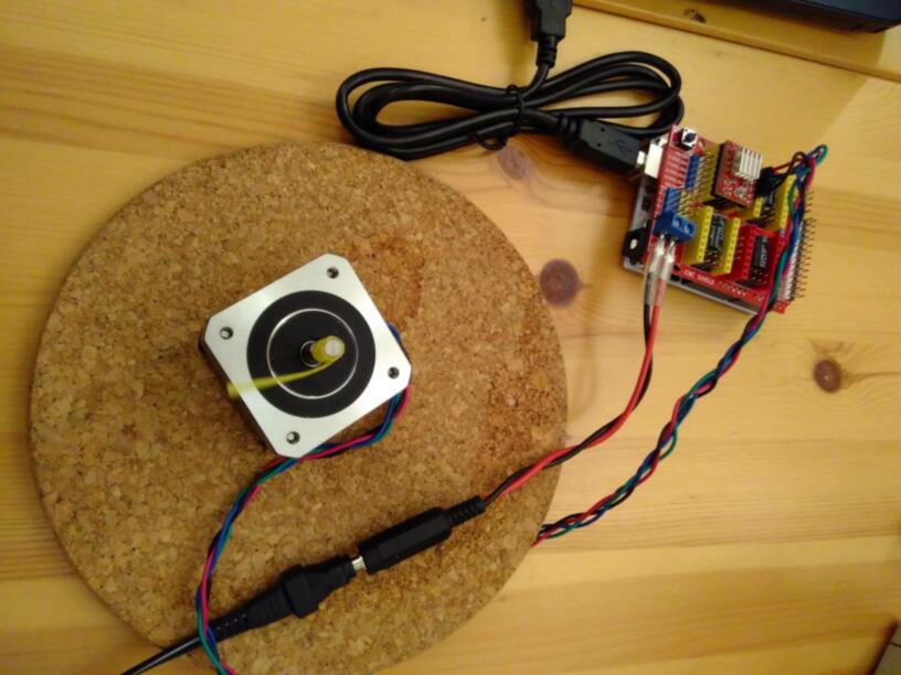
First test failed with the connections given in the datasheet!!! After measuring the impedances and connecting the wires correctly (see above), I manage to have my motor turning:
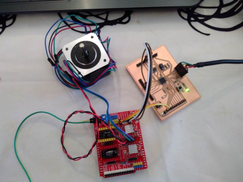
Second test with my main board, ARD-CNC-kit1 and OSM stepper motor
In order to use my main board in place of the Arduino UNO, at the hardware level, I have to:
- connect the ARD-CNC shield to the main board through
| shield pin name | Arduino pin # | ATmega328p pin # | pin description |
|---|---|---|---|
| GND | main board GND | logic power supply | |
| 5V | main board 5V | logic power supply | |
| EN | 8 | 12 | Enable pin for all stepper outputs |
| X_DIR | 5 | 9 | Direction-Pin for X-axis |
| X_STEP | 2 | 32 | Step-Pin for X-axis |
I now take the connections on top of the shield, as the latest doesn’t fit in any breadboard!!
I use the same program as in previous test.
Here is the setup:
Third test with my main board, Stepper 2 click and OSM stepper motor
Let’s have a look to the Stepper 2 click:
A set of three onboard jumpers (J1-J3) allow to switch between the different stepping modes, as seen in theA4988 datasheet: J1, J2 and J3 jumpers provide a way to set the M1, M2 and M3 pins respectively to VCC. Default position is to leave the M1, M2, M3 pins unconnected, meaning applying full step (here 1.8°).
Stepper 2 click features three pairs of screw terminals:
- 2B and 2A, on CN2, connected respectively to pins OUT2B and OUT2A of the A4988 for connecting coil 2 of the stepper motor
- 1B and 1A, on CN1, connected respectively to pins OUT1B and OUT1A of the A4988, for connecting coil1 of the stepper motor,
- VIN, connected to pins VBB1 and VBB2 of the A4988, and GND, connected to pin GND of the A4988, are for bringing an external power supply, depending on the motor. The output drive capacity of the motor is up to 35V and ±2A. With the OSM motor, I need a 12VDC power supply. With the Sanyo Denki motor, I need a 24VDC power supply.
The connections to make with my main board holding the microcontroller are as follows (keeping the same pins as in previous tests):
- connect the EN pin to pin 12 of the ATmega328p
- connect the RST (RESET, active low) pin to 5V
- connect the SL (SLEEP, active low) pin to 5V
- connect the ST (STEP) pin to pin 32 of the ATmega328p
- connect the DIR (DIR) pin to pin 9 of the ATmega328p
- connect the 5V pin to +5V
- connect the 3.3V pin, which is also compatible with 5V logic, (VCC) and GND pins of the Stepper 2 click to 5V and GND pins on main board.
After a preliminary test, we see that the Sanyo Denki motor requires more current than the first OSM motor (2.85 A, against 2A), so we will not use it with the Stepper 2 click that only allows 2A.
So, let’s go for the making of the support board for the Stepper 2 click…
Support board
Specific board and packaging will be required when using the motor and its driver in real project…
We do not have to forget to add a reverse voltage protection…
So I will develop here a support board that can be used with all Mikroelektronica shields ( e.g. my DHT22 2 click and my Stepper 2 click), composed of pinheaders to receive the shield, and a P-channel MOSFET as reverse voltage protection. This is an better approach than a simple diode, which will generate voltage drop and power loss. Nice explanations can be found here:
Take care to use the right P-MOSFET: check its drain-source voltage rating, RDS(on) as small as possible to reduce power losses, and maximum gate-source voltage.
Step 1 - PCB Design
As in previous assignments, I use kiCad to design my board, double sided.
Here is the schematic:
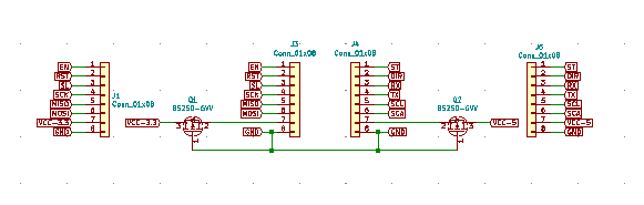
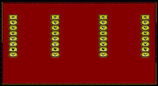
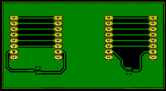
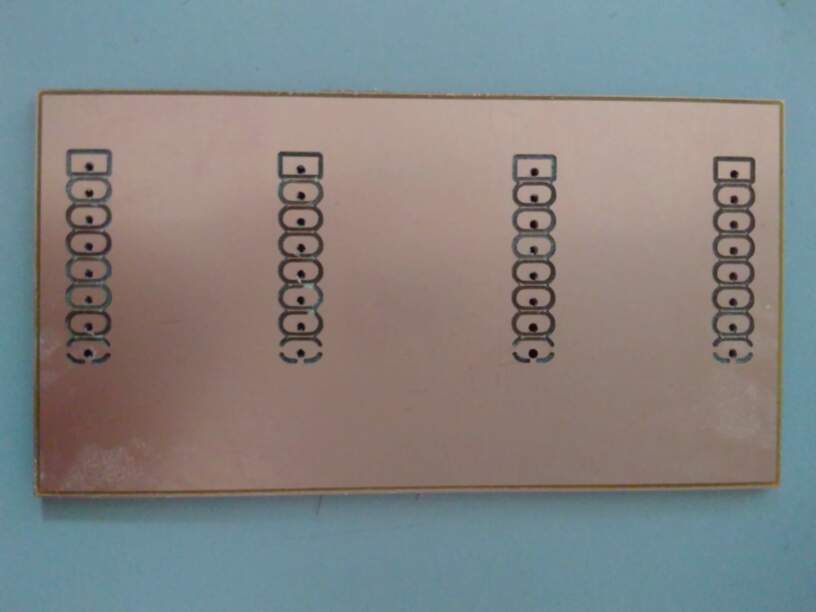
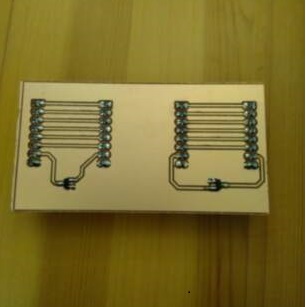
And the top and bottom layers:
The complete files are available here.
Step 2 - PCB Fabrication
I mill the PCB on a double-sided FR1 board (standard size 127 x 101.6 x 1.70mm) on the Bantam milling machine, following the same process as in week07.
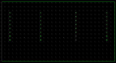
Therefore, I load the three gerber files of the outline, top and bottom layers, as created by Kicad, as well as the drill file, into the Bantam software.
A first attempt with 1/64” and 1/32” flat end mills in a unique process leads to strange result: the ground pads are not separated at all from the ground plane (no thermal pads!), although it is the case in the gerber file!!!
So, I made a second PCB, making the traces with the 1/64” flat end mill only, using the 1/32” flat end mill for the outline and the drill only.
Result looks better:
| top layer | bottom layer |
|---|---|
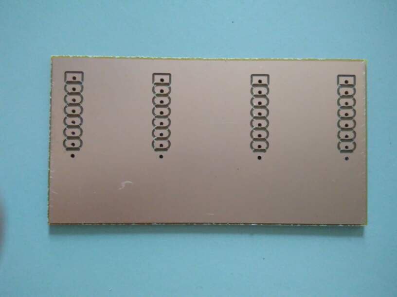 |
|
 |
 |
Another intriguing fact is that the ground plane piece on the left side, is not supposed to exist in the gerber file.
Step 3 - PCB assembly and testing
The Bill of materials is as follows:
| Id | Designator | Description | Quantity |
|---|---|---|---|
| 1 | JP1, JP4 | PinHeader_1x8_P2.54mm_Vertical | 2 |
| 2 | JP2, JP3 | Socket_1x8_P2.54mm_Vertical | 2 |
| 3 | Q1, Q2 | BS250 P-channel MOSFET, SOT-23 | 2 |
No special issue for the soldering process, except that in order to connect the ground on both side, I started to put some solder on the top face on the ground pads.
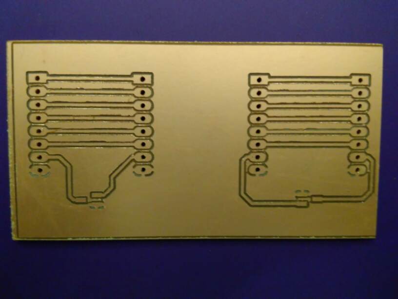
Here is the result of the assembled board:
 |
 |
|---|---|
Continuity checks went smooth, no issue…
Test of the reverse voltage protection: it works!
| correct voltage | reverse voltage |
|---|---|
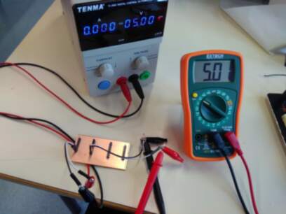 |
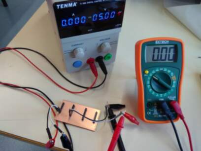 |
Step 4: Programming
I use the same software as previously..
Functional tests
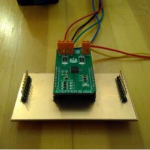
Here is the setup:
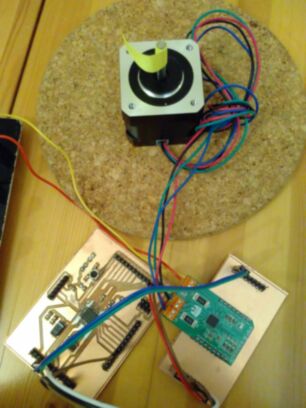
FAILED: The system doesn’t function.
Murphy’s law being valid, I killed my mainboard in the process.
So I tried to understand and locate the issue by making different tests. It took me quite a few hours of work…
- Check all connections and voltages
- Change Stepper click to another one
- Arduino NANO (RIP my mainboard) with Stepper click on my shieldboard: it does’nt function, although the voltages have the correct values at the pins level
- Arduino NANO with Stepper click on breadboard: it works.
- Arduino NANO with Stepper click on breadboard, together with connections to the shieldboard on the corresponding pins. Everything’s fine until I try to connect the RST pin, DAMNED, here it is!!
After rechecking for short circuits around the incriminated pads (RST and EN).. It finally worked!!
Still to do if I had time....
Make a new mainboard…