20. Project development
I’ll summarize here the several steps done during the assignments to work on my final project…
Week 01
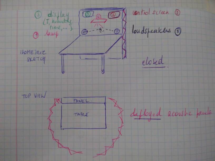
This was the starting point of my project, after discussion with colleagues of the Applied Arts department… First sketch of the project
Week 02
This assignment gave me the basis to work with websites and version control with git repositories. This will be useful to create a website to promote my project and to keep the upcoming versions of web data, designs data, software, users guide, etc.
Week 03
CAD will be an important tool to create the design of the different pieces of my structure: motor support, frames…
Week 04
Laser cutting will probably be THE tool to create the working surface and seat of my alcove office. And also cutting the felt of the booth structure…
Week 05, 07, 09, 11 and 12, 14 and 16
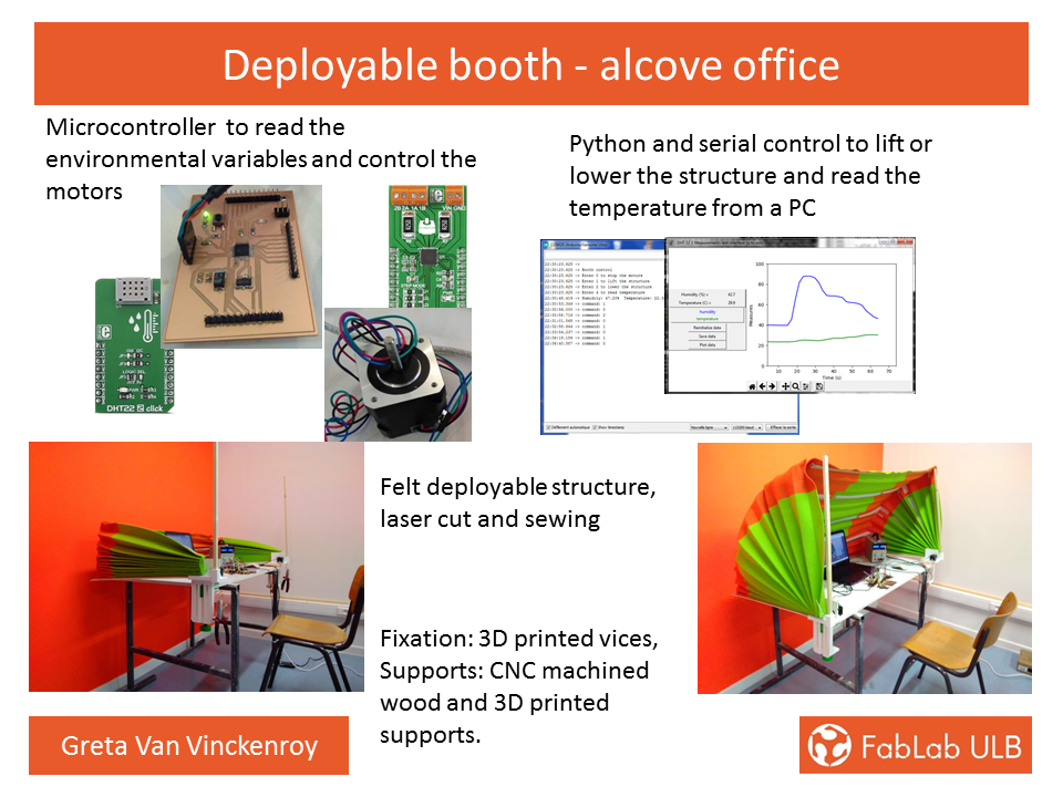
With my project in mind and my experience in electronics, this is the core part of my structure: A microcontroller and its extension for input (environmental data sensor; temperature, humidity), output ( motor control to deploy the booth), user interface and communication will be required to automate and ease the booth use.
Week 06
3D print will be useful to create the motor support as a minimum, probably the articulation of the deployable structure.
Week 08
Computer controlled machining will be used to create the seat, and planar working surface of the office.
Week 10
Molding and casting is probably the less visible but still essential part of the job, to create a box to protect all the electronics parts…
Week 13
This was the starting point to see the different aspects to look at when designing something new. But I’m not able yet to evaluate costs and answer complex questions as long as the prototype is not functioning…But this is a good preparation exercise to ask questions…
Week 15, 17
mechanical design questions will probably arise while making the prototype, but I don’t have clear ideas about it yet…
Week 18
Wild card week: this was a good opportunity to start working with deployable structure, but the lack of time and material delivery will delay experimentation with those materials.
Week 19
Again, to soon to elaborate the dissemination plan, but I’ll definitely take some time to answer them ASAP.
Week 20
Here we are, far from done.. An extra month will be needed to complete my project, second full time job…
And final sketch, from week20:
UPDATE -SEPTEMBER 2019
Having decided to present the final project before next cycle, I’ll develop here in details the different steps I followed to finalize the project.
Mechanical design - Storage case
The idea is to have a case in an U form, that can be fixed on the table (60x120cm) - without damaging it, and that supports the felt structure when it is not in use, as well as the controlling electronics.
The idea is to have a light wood case, to be fixed on the table.
After some (long) reflexion and looking through the Internet, it has been decided to design 3D printed parts that will also allow to fix the motors at both ends to control the deployment of the felt structure.
A vice is probably the best suited way to do it, in order to account for the variable table thickness, without damaging it.
Wood support
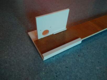
For the first prototype, a simple horizontal wood support will be used, not a complete case.
The wood structure is cut following a given pattern, taking into account the size limitation of the cutting/machining machines:
if we use the laser cutting, with a 3mm thick MDF (medium density fiberboard) wood:
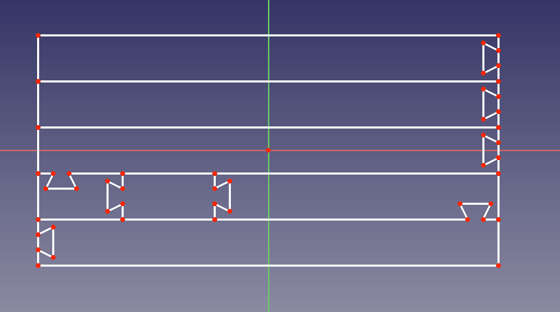
We’ve first tried with an 8.5mm thick plywood panel to be machined on the CNC, as the latest allows bigger dimensions (60 x 110 cm) and stiffness of the whole structure will probably be better. 12mm OSB (Oriented Strand Board) could be an option, but it would be a quite heavy structure…
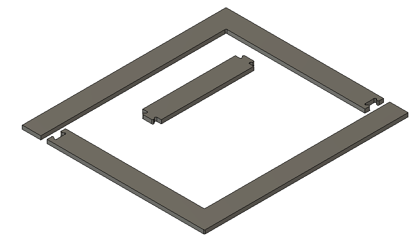
The complete Fusion360 files are available here.
We fix the plywood panel in the CNC machine (see week08) for details of the procedure), and after a few hours and correction of some mistakes, some sandpaper rectification of the profile, a good hammer hit,to get a nice press fit… here is the wood support:
Auto-adhesive velcro is placed on top side, to enable latter fixing of the felt structure:
Bill of materials
OSB panel 10.29€
MDF panel 7.99€
plywood panel 33.99€
Luckily I got it for free, as I already had panels at home…
Mechanical design - Felt structure
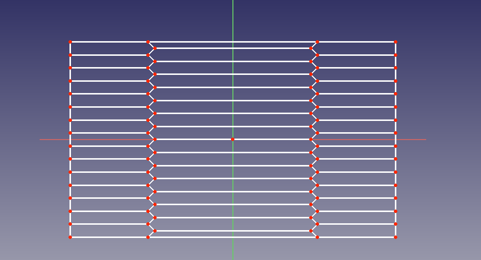
The first step is to design the geometry of the deployable structure.
Typical dimensions of office tables are minimum 60 x 120cm, to 80 x 160cm as a maximum. We will use the minimum dimensions as a basis for our first prototype.
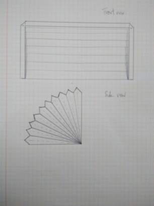
The minimum height of the booth should be about 60cm, to allow the user to seat comfortably in front of it.
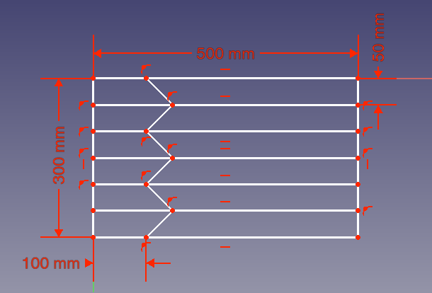
This will define the geometry of the structure, as given in the sketch below:
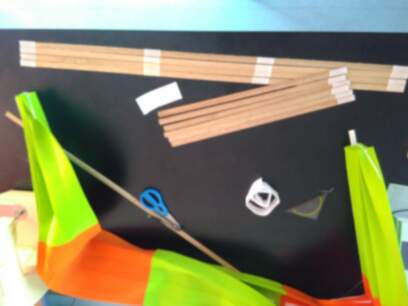
Plane surface with folding pattern: * 5-cm wide strips * width of 125cm minimum, ideally 150cm (this will gives 30 plies of 5cm wide strips) * length of (2x60 + 120 + 2x5 =) 250 cm
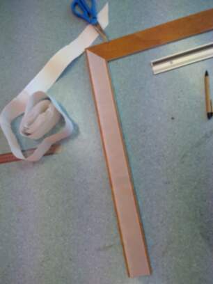
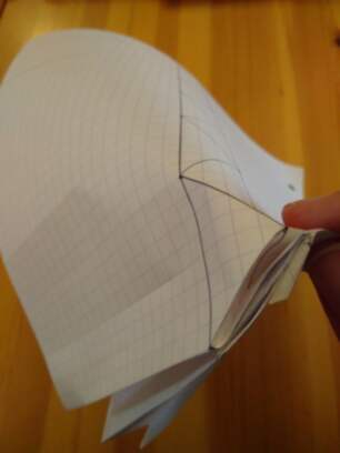
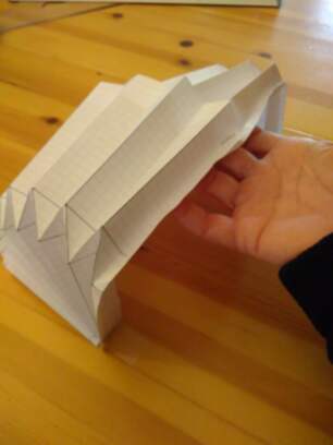
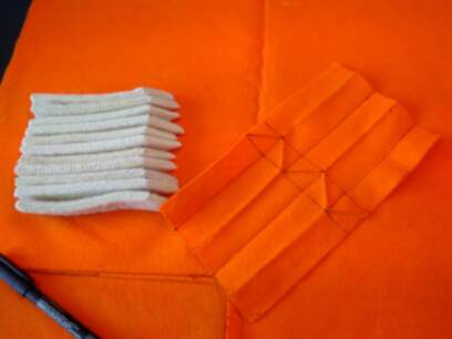
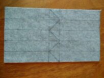
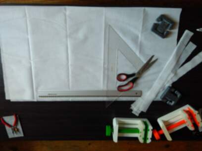
Proof of concept on paper:
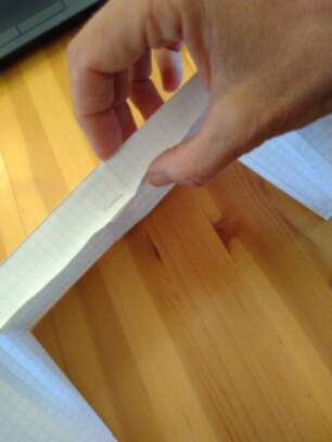
Half of the folding pattern is drawn on scale 9/60 and two similar planes are drawn. This to ease the folding process.
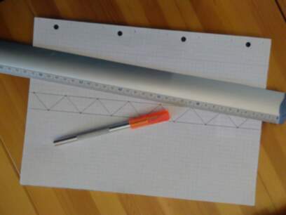
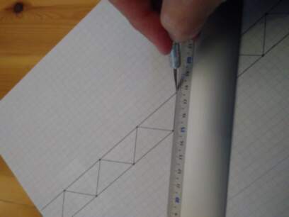
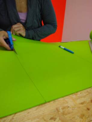
Paper is slightly cut on top side of the edges (other side of the sheet for the hollows)
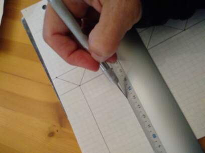
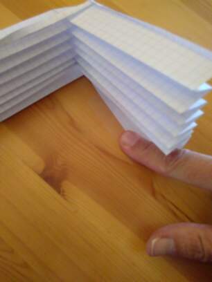
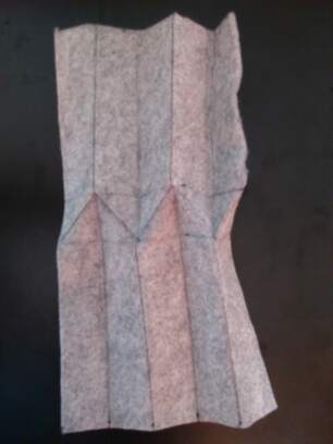
Folding process starts from one end towards the other end, ensuring the construction of the 3D structure:
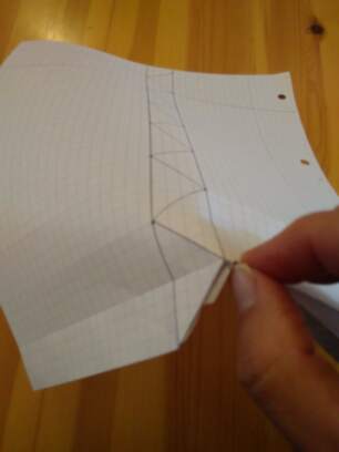
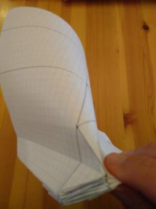
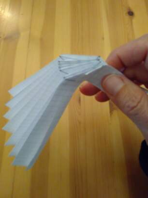
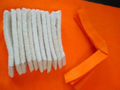
Two similar structures are built following hte same process:
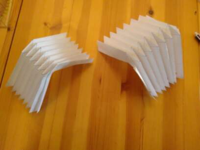
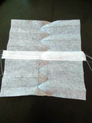
Both structures are linked after folding and fixed on table with adhesive paper:
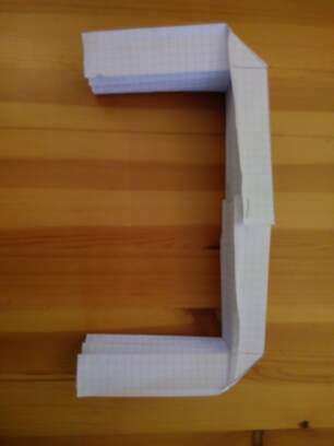
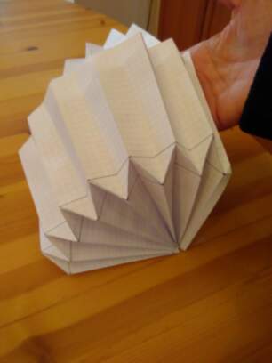
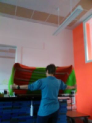
And here is the resulting structure:
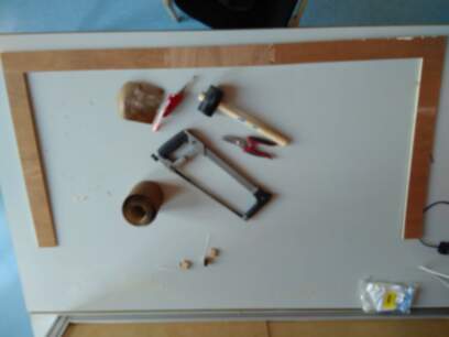
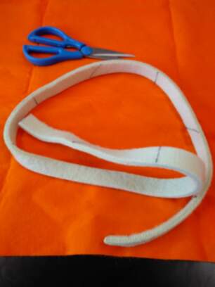
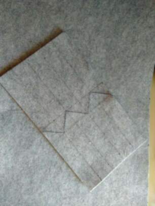
Preliminary tests on the felt structure
A first test is performed with a felt of less than one millimeter thickness.
A thicker felt reinforcement could be glued on the thin support, cut following the folding pattern:
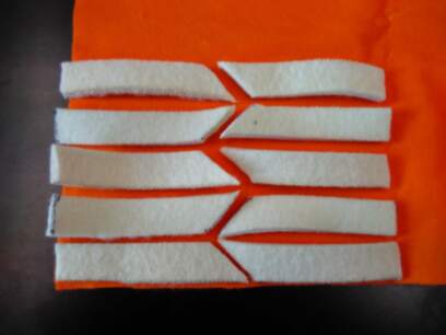
Folding the thin felt tissue is done easily, ironing does definitely help keeping the pattern, even flat!
But assembling a complete structure on this manner will get me crazy, so I decided to go ahead with a 3mm felt support, without additional reinforcement.
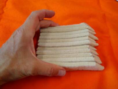
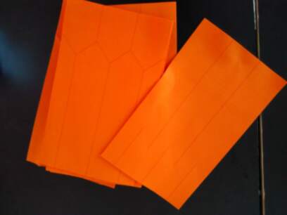
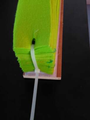
Folding the thicker felt is, as expected, more difficult, ironing doesn’t help, but slightly cutting the edges - with a cutter - on half a millimeter depth helps keeping the pattern.
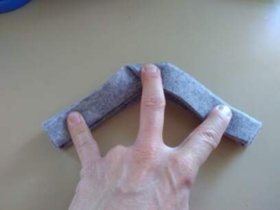
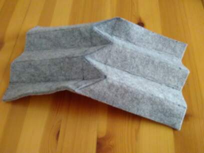
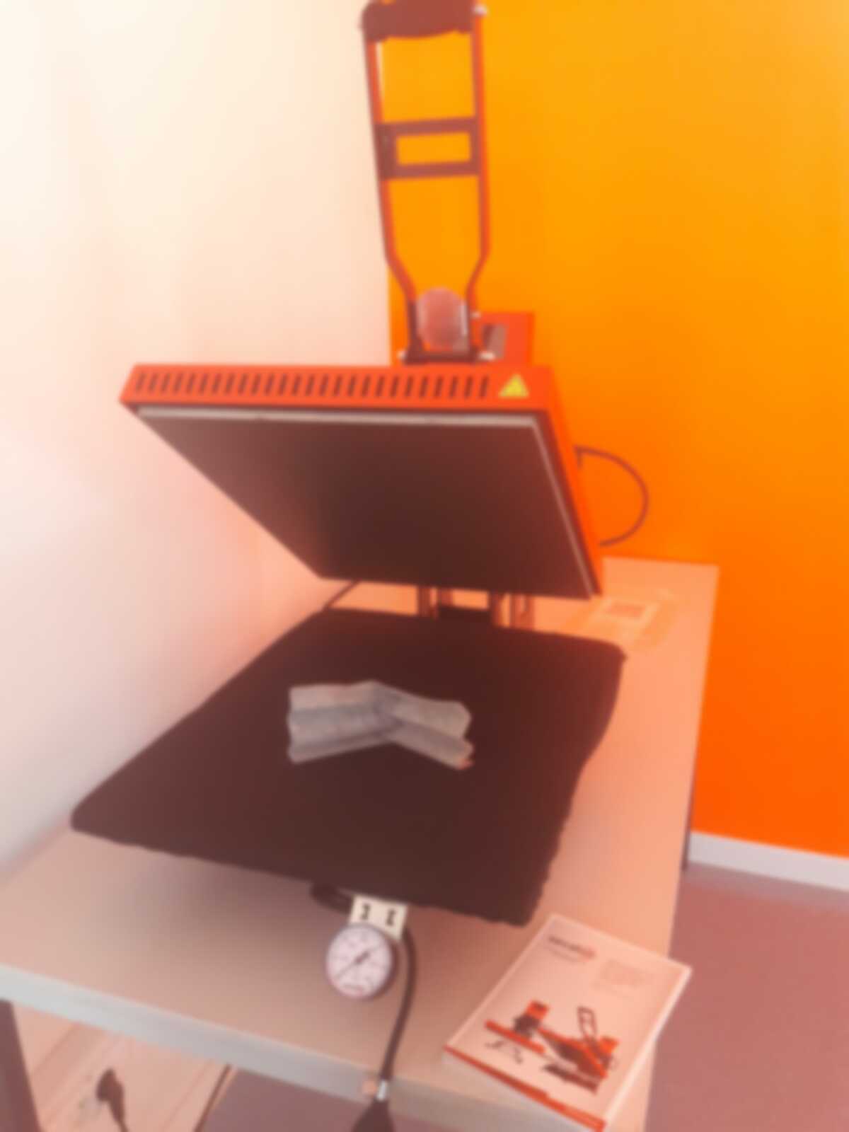
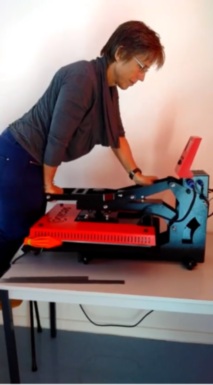
In addition, the use of a heat press, keeping the felt for 40sec @150°C, helps also keeping the folding pattern, as illustrated below:
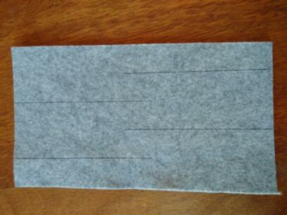
We redo the test, using the laser cutting machine this time, to define the correct parameters for engraving and cutting.
The laser cutting machine handbook EPILOG MINI recommends following parameters for fleece material, for a 60W machine:
- Engraving: raster, 600DPI, speed: 90, power 20
- Cutting 3mm: vector,pulse frequency: 500, speed 25, power 10:
Cutting is performed in three steps:
-
First engraving and cutting from top side, with proposed parameters
-
Engraving from bottom side increasing the power for engraving to 30 (lines need to be deeper…)
- Engraving the diagonal lines on top side with a speed of 80 and power of 30, because they were definitely not sufficiently marked…
Heatpress for 40sec @150°C is again used. Here is the result:
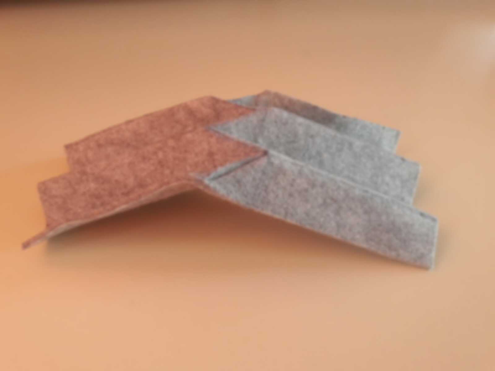
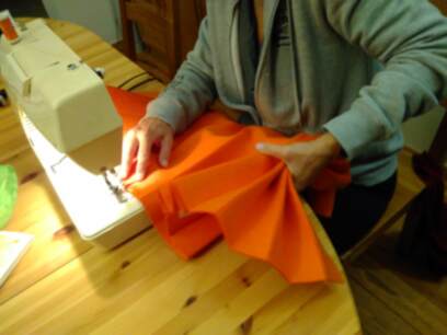
Stitching several pieces together,and adding a heat-sealable material to ensure correct alignment during stitching seems successful:
The impact of the heat-sealable material is limited in the folding process if it is placed on the inner side of the ply, but aesthetically, its better to place it in the inside…
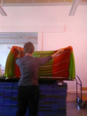
Full scale felt structure
Given the results of the tests, and the limitations of the available laser cutting machine, it has been decided to use 4mm thick felt panels, of size 30cm x 50cm, laser cut on one millimeter depth, set in the heat press, stitching separate pieces after use of heat-sealable fabric on the joint limit.
Laser cutting
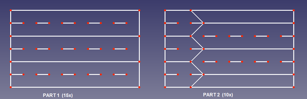
Given the limitations in size of the laser cutting machine (60cm x 30cm), the complete structure is divided in 5x5 pieces of 50 by 30 cm. Two similar patterns are created on the felt:
-
PART1: One pattern with parallel lines only for the surface outside the corners. 15 pieces are required.
-
PART2: One pattern covering the corners with the triangles to realize the folding pattern. 10 pieces are required.
Continuous line is a carving on top side to facilitate folding, dotted lines are carving on the bottom side to facilitate folding in opposite direction.
A unique dxf file is created, imported in CoralDraw and edited accordingly in the latest software to create the different parts, cutting on top and then on bottom by turning them over.
Cutting is performed in a slightly different way than for the test coupons, only vector cutting is used, to gain time, increasing the speed to 100% to avoid complete cutting. So:
- Engraving: vector, pulse frequency: 500, speed: 100, power 10
- Cutting: vector, pulse frequency: 500, speed 24, power 10.
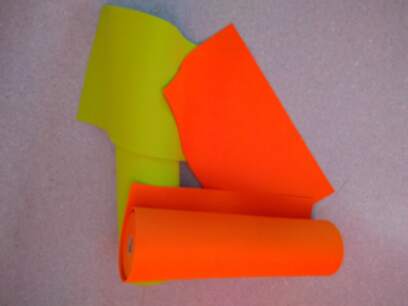
Prior to laser cutting, a raw cut of the felt rolls is performed to be able to have panel usable in the laser cutting machine.
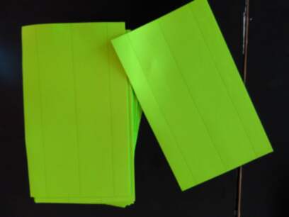
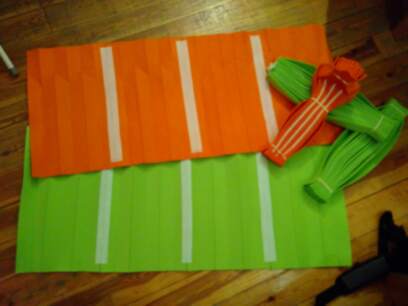
Here are the results:
Additional holes are made on the part1 panels to be placed along the short side of the table. This to be able to pass a wire to keep the structure locally closed.
The heatpressing process requires some force thanks to the plies thickness…
Assembling
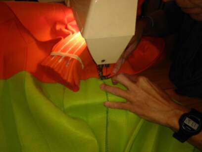
The several pieces are stitched together to recreate the complete structure. Some edges are reinforced with heat sealable textile. This will also help the stitching process:
Subsequently, all parts are stitched together
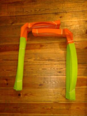
The folded structure will be fixed on its support through velcro strips, to be stitched on one side:
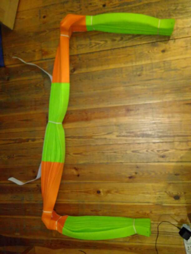

Hose clip are inserted at the ends:
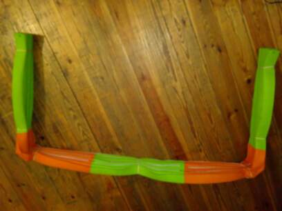
And the whole structure is set on the support:
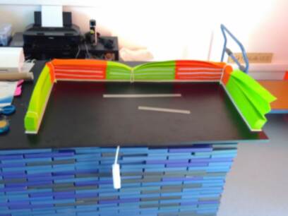
But it still requires some stiffening:
Stiffening
Thin plastic rod need to be fixed on the felt (through a tubular slide sewn onto the felt) to fix the whole structure on the support and to enable the motor controlled opening/closing.
Another faster and preferred alternative is a wooden profile fixed by velcro, insuring a better transversal rigidity:
Here we have:
The whole felt structure weights about 1.8kg. If we add the wood stiffener, it reaches 2kg. This will impact the choice of the motor… and the design!
Intituively, a brushless DC motor is probably the best solution to control the movement of the structure, but I run out of time to test it.. As a first test, we use the stepper motors used in assignment of week20 and adapt the movement control in a easy and rapid way to be able to use the stepper motor anyway. We’ll come back to this point latter on, while building the supports.
Bill of materials
The bill of materials is as follows:
| Material | # | pkg | # | p/unity | price |
|---|---|---|---|---|---|
| Felt, 4mm thick | 3.75m² | 7.5m of a 0.5(3)m width roll, 5m long | 2 | 6.9628€/m | 69.628€ |
| plastic rod, 11mm wide | 3m | 3m out of a 100m box | 1 | 1.10€/m | (not used) |
| tubular slide | 3m | 3m out of a 50m box | 1 | 1.80€/m | (not used) |
| velcro strips, 20mm wide | 3m | 3m out of a 25m box | 1 | 2.80€/m | 8.4€ |
| heat-sealable A3 sheet | 0.8m², 1 A3 sheet | 1 out of a box of 6 A3 sheets | 1 | 3.65 €/sheet | 3.65€ |
| white sewing thread | 200m spool | 1 | 3.75€ | 3.75€ | |
| strong green sewing thread | 30m spool | 2 | 2.65€ | 5.3€ | |
| green sewing thread | 200m spool | 1 | 3.75€ | 3.75€ | |
| orange sewing thread | 200m spool | 1 | 3.75€ | 3.75€ | |
| stiffening wood | rods of 18x190mmx240cm | 4 | 5,79€ | 23.16€ | |
| fixing screws | 13€ |
Mechanical design - 3D printed fixations
Design
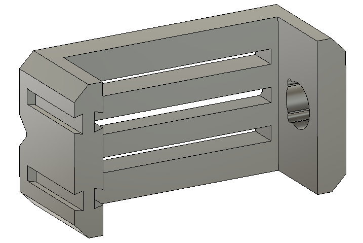
Looking on Thingiverse, I found a interesting vice project, that I decided to adapt to my project. Namely, it is the bottom platform that needs to be adapted to add additional slots: those will allow to add motor and wood structure supports to the vice.
To do this, in Fusion360,
-
removed the side slots for screw fixation, refilled the space to recreate straight edges (
create-loftcommands) -
removed the chamfer on top side
-
add top slots ( using the
mirrorandextrudecommands).
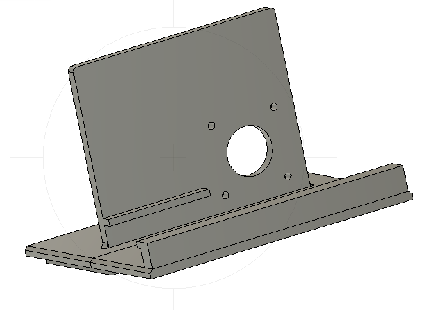
The new pieces, namely the motor support and the PCB support are created with the plate as starting point:
- new sketch based on the profile of the plate, reduced by 20mm in width (by moving the edges of 10mm each side):
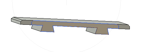
- extrusion to create the support plate:
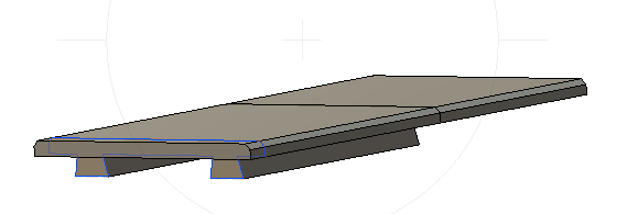
- new sketch and volume to fix the stepper motor holder:
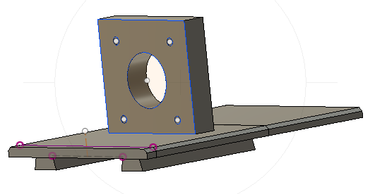
- new sketch and volume to clamp the wood plate:
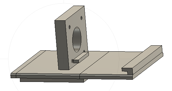
- new sketch and volume to reinforce the motor holder:
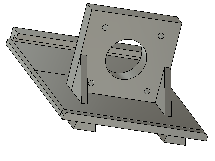
- join the different volumes and create the needed fillets:
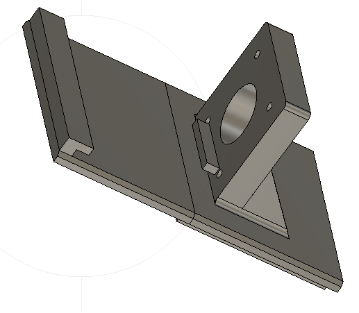
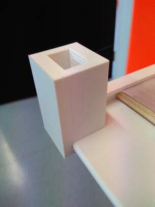
- move the support to the right or left to place the motor on the corner of the table, add vertical wall to keep the folded structure in place.
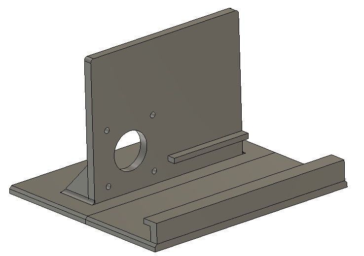
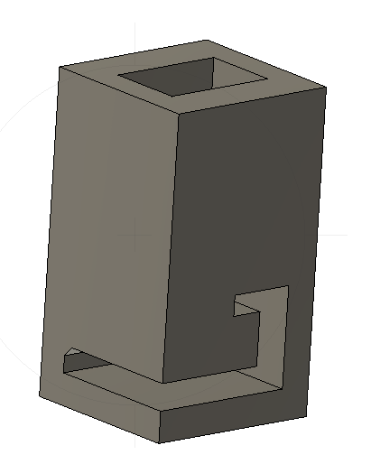
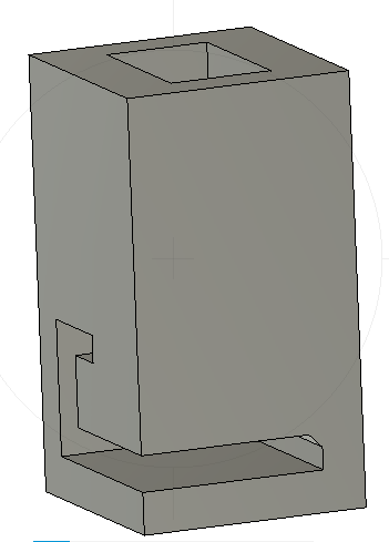
In addition to previous parts, a rod support is made, in order to facilitate the lifting/lowering of the structure. To make it simple, we use the capability of Fusion 360 to “cut” a body with existing bodies.
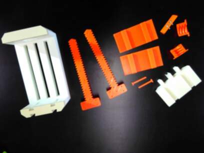
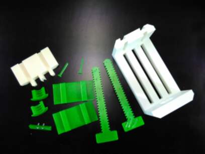
So, the STL files used here are given below:
| Part pic | Part description | # | stl |
|---|---|---|---|
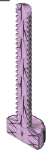 |
Half bolt_1 | 1 | stl |
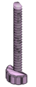 |
Half_bolt_2 | 1 | stl |
 |
Half_screw_nut_1 | 1 | stl |
 |
Half_screw_nut_2 | 1 | stl |
 |
Screw lock | 2 | stl |
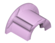
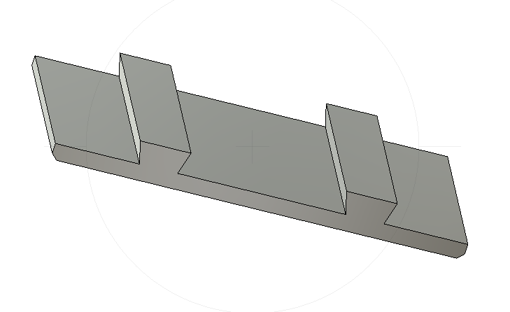 |
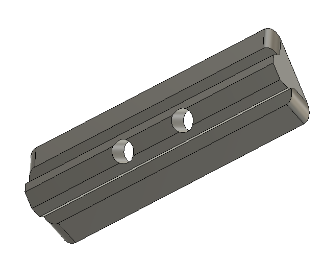
Plate | 2 | stl |
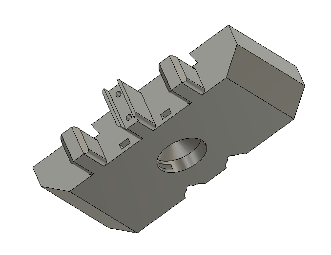 |
Mobile platform | 1 | stl |
 |
Bottom slider | 1 | stl |
 |
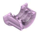
Bottom platform | 1 | stl |
|
Motor support - right | 1 | stl |
 |
Motor support - left | 1 | stl |
 |
left rod support | 1 | stl |
 |
right rod support | 1 | stl |
Making of
The several pieces are printed in PETG and the platforms (mobile and bottom) are printed in PLA.
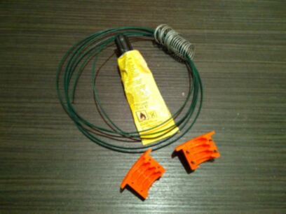
Several issues have been encountered during the fabrication of the bottom platform, the largest piece, that required 17 hours to be made…
Assembling of both halfs of the screw nut and the bolt is done by gluing a small iron wire in the holes and fixing both pieces in a vice during the glue drying process.
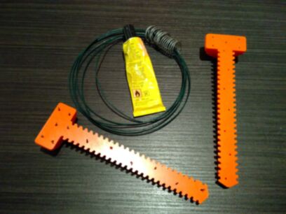
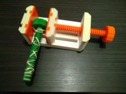
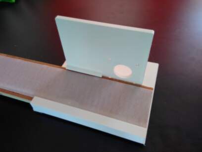
The wood plate fits perfectly in its supports:
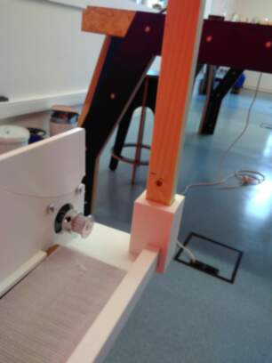
And the wooden rod is fixed on both sides of the table, through its supports:
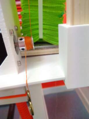
Sewing wire is used to attach the felt structure to the motor, through a screw hook on the top of the supporting rod: one end of the wire is attached to the stiffening wood of the structure. The other end of the wire is wound around the motor shaft, with a counterweight:
Here is the complete structure:
Bill of materials
To make all the 3D printed parts, I used at least one reel of PLA and another one of PETG. Those are available at the lab, but I checked the price at the store:
| material | p/unity(reel) |
|---|---|
| PLA | 27.95€ |
| PET-G | 30.95€ |
Electronics
Hardware
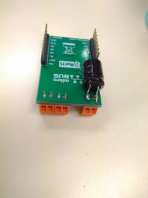
Due to lack of time, I reuse the different designs done in previous assignments of week 11 and 12. And make some adjustments:
- Add a 100uF - 50V on the stepper 2 click, to protect the IC against overvoltage, as I killed a motor driver due to the absence of any protection on the stepper click, unsane!
As already done in previous assignments, the different steps followed to realize the PCB’s (mainboard and shieldboards) are:
- PCB Fabrication
- Continuity checks
- Assembly of components, starting from the smallest components to the largest: on the main board, i.e. the microcontroller up to the pinheaders
- Continuity checks
- Programming of the microcontroller through a USBTinyISP
- Serial programming of the code through the FTDI connector
The three last steps have been quite time consuming, mainly due to microcuts in the tracks....
Bill of materials
The bill of materials is as follows:
Mainboard:
| Id | Designator | Description | Quantity |
|---|---|---|---|
| 1 | R2,R3 | 330 R R_1206_3216Metric_Pad1.42x1.75mm_HandSolder | 2 |
| 2 | JP2 | SPI connetor: PinHeader_2x03_P2.54mm_Vertical | 1 |
| 3 | Y1 | 20MHz Resonator_SMD_Kyocera-3Pin_7.4x3.4mm_HandSoldering | 1 |
| 4 | U1 | ATmega328P-AU TQFP-32_7x7mm_P0.8mm | 1 |
| 5 | S1 | Push button FSM-SWITCH | 1 |
| 6 | R1 | 10K R_1206_3216Metric_Pad1.42x1.75mm_HandSolder | 1 |
| 7 | JP1 | FTDI PinHeader_1x6_P2.54mm_Vertical-GVV | 1 |
| 8 | D2 | RED LED_1206_3216Metric_Pad1.42x1.75mm_HandSolder | 1 |
| 9 | D1 | GREEN LED_1206_3216Metric_Pad1.42x1.75mm_HandSolder | 1 |
| 10 | C5,C2,C1 | 0.1uF C_1206_3216Metric_Pad1.42x1.75mm_HandSolder | 3 |
| 11 | C4 | 1.0uF C_1206_3216Metric_Pad1.42x1.75mm_HandSolder | 1 |
| 12 | C3 | 47uF C_2816_7142Metric_Pad3.20x4.45mm_HandSolder | 1 |
Shieldboards:
| Id | Designator | Description | Quantity | Price |
|---|---|---|---|---|
| 13 | Q1, Q2 | BS250 P-channel MOSFET, SOT-23 | 6 | 15.96€ |
| 14 | JP1, JP4 | PinHeader_1x8_P2.54mm_Vertical | 2 | 2.329€ |
| 15 | JP2, JP3 | Socket_1x8_P2.54mm_Vertical | 2 | 5.46€ |
| 16 | X1 | Motor driver (Stepper click) | 2 | 41.76€ |
| 15 | X2 | Temperature and humidity sensor (DHT22) | 1 | 23.24€ |
Of course, the FR1-based double sided PCB is required…
I do not put all prices in details, except for the ones specific to this project (the shieldboards) those materials are available at the lab…
Software
For the software, I reuse the Arduino sketches and make some adjustements while combining them to have one and only soft running.
As usual, I performed tests in phase in order to cope with one problem at a time…
Motion control test
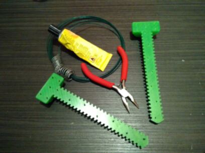
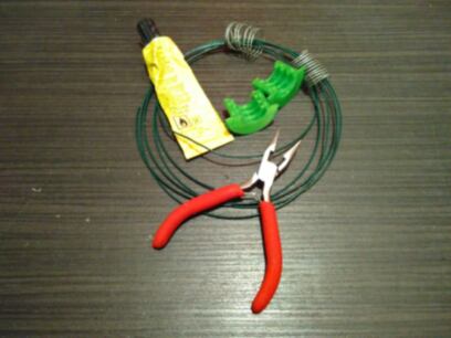
A first phase of tests is performed with the ARD-CNC shield on a Arduino UNO, with the sketch motors_control. These tests allow us to determine the correct wounding of the wire on the shafts, the correct counterweight (after several trials with the only weights available: tools!!).
For this first test, some conclusions may already be drawn:
- Incorrect winding of the wire on the shafts leads to broken wires
- Screw hook on the top is ok, but not the ideal method
- The motor support is not stiff enough to hold the force: the rod is bended towards the felt structure.
- Adapted weights would be more easy to use as counterweights than tools!! Too light weight or too heavy weights make that the motion control doesn’t work properly. About 300g counterweight is ok, but some dissymetries may occur, depending on the motor torque.
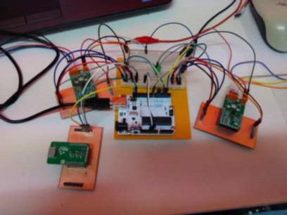
Motor Drivers test
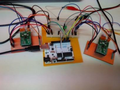
I now replace the ARD-CNC kit by my shieldboards with their respective motor drivers (left and right), taking care for the connections, which I choose as follows:
| pin on shield | motor wires |
|---|---|
| 1A | blue |
| 1B | red |
| 2A | green |
| 2B | black |
Given the winding of the wires on the shafts, lifting the structure requires to turn the right motor counterclockwise and the left motor clockwise. Small adaptation to the software to take this into account.
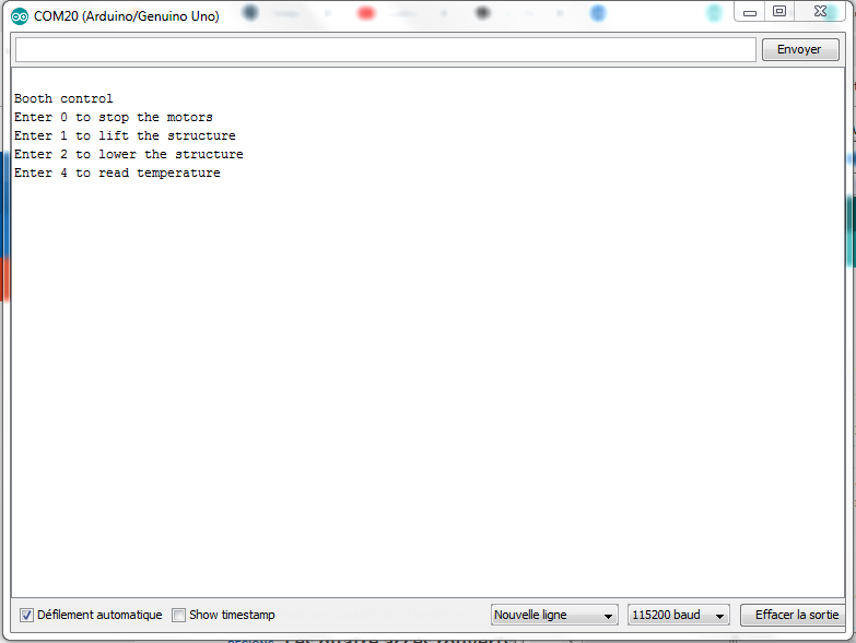
In addition, I add the possibility to control the structure lifting through serial commands.
The Arduino sketch (motors_control.ino) is available here.
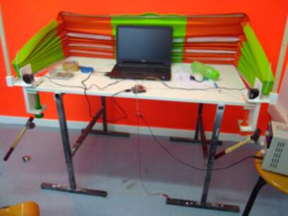
The setup:
This works fine.
Temperature sensor test
I reuse the code from assignment of week14, using the sensor in I2C mode, and integrate it with the code to control the motor written above. I add the possibility to ask, from the PC, to get the temperature and humidity.
The final Arduino sketch (mobile_booth.ino) is available here.
The setup:
This works fine…
Mainboard tests
Last but not least, I now replace the Arduino UNO with my mainboard and place the complete electronics in a box (lasercut):
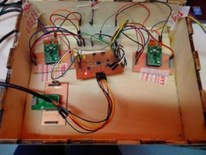
Here we are, check the video…