Assignment 4: Electronics Production
Project Description
Fabricate and populate a PCB
Assignment Details
- Group Assignment:
- Characterize the design rules for your PCB production process
- Individual assignment:
- Make an in-circuit programmer by milling the PCB
- Check if you can program it, then optionally try other PCB processes
Background - Building the CNC
One of the themes of the class appears to be to bootstrap the making process. In this spirit and also because I am doing the class as a remote student, I decided to mill the PCB on a CNC that I built. I put together a Sienci CNC mill One, Arduino Grbl based router CNC. I intend to use this for any small CNC work. The following pictures show the process of building the CNC.
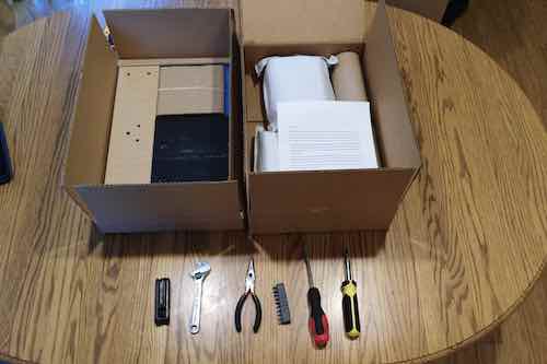
Here are the boxes of CNC parts.
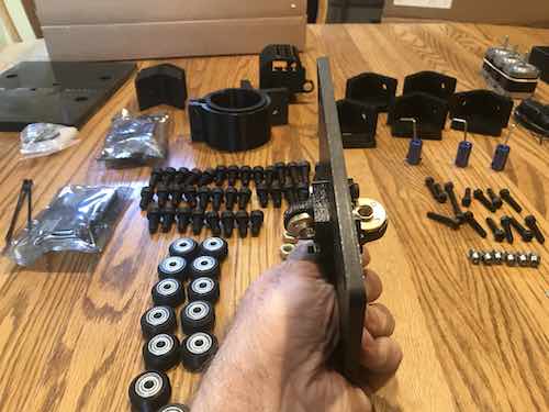
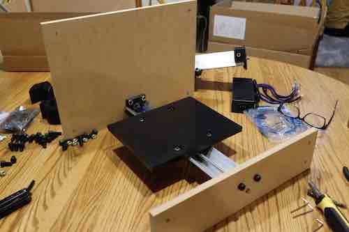
Attaching the brackets for the lead screws to the gantry.
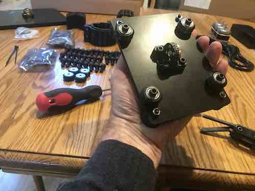
Attaching the rollers to the gantry.
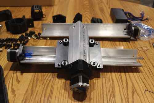
Completed gantries.
Y Axis gantry attached to frame.
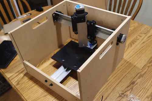
Remaining gantries attached to frame.
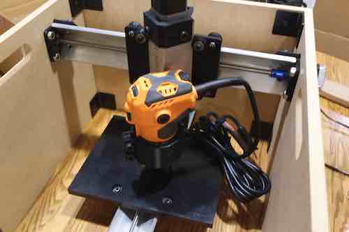
Finished CNC with Router.
Characterize the design rules for your PCB production process
Here is the process that I used to move from the PNG to a milled PCB:
- Import the PCB PNG into Inkscape
- Execute the Trace Bitmap command to create vector paths from the bitmap
- Export the paths in a .SVG file
- Import the .SVG file into the Easel CAM tool
- Use Easel to position the PCB cuts on copper board
- Use Easel to the feeds, speeds and cut distance
- Generate and export G-Code
- Import the G-Code into Universal G-Code Sender (UGS)
- Use UGS to connect to the CNC
- Jog the cutter and set 0's on the 3 axies
- Send the G-Code to the CNC (One for the traces, One to cut the outline)
Here are my final CNC settings:
- Feed Rate (mm/min): 800
- Plunge Rate (mm/min): 100
- Step Over (mm/min): 0.3
- Cut Depth (mm): 0.4
- Spindle Speed (RPM): 20000
- Pocket Cut End Mill Diameter: 1/8"
- PCB Trace End Mill Diameter: 1/64"
- PCB Outline Cut End Mill Diameter: 1/32"
Make an in-circuit programmer by milling the PCB
Here is how I milled the PCB:
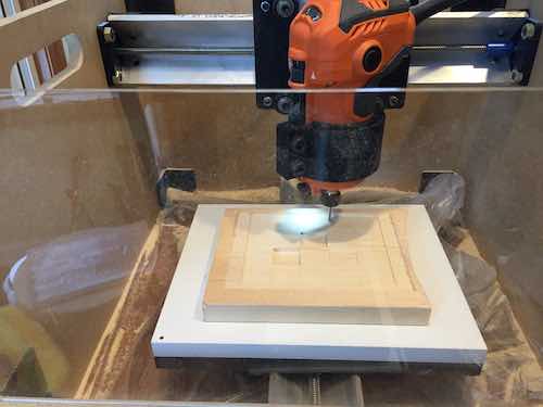
This is the first time that I am using this CNC, so I wanted to do some test cuts before using the fragile 1/64 end mill. I also wanted to validate that the requested stepper motor movement matched what was expected. (Initially the machine moved twice as far as expected in x and y. I went back and found that I had placed the jumpers on the wrong pins on the motor controller shield.) Next I cut a series of pockets to validate the z axis. I jogged the bit to just touch the top the machined piece with a piece of paper in-between moving back and forth to validate the end mill position. (Basically the same as leveling a 3D printer bed.) I used the steps listed above in Easel to generate several cut pockets of different depths to validate the z axis depth cut. I got inconsistent results with this test. My assumption is that this was due to the thickness varying over the board. This could result in a z-0 value was below the surface of the piece for some of the cuts, causing the pocket to be deeper than expected. To correct this problem, I milled large pocket to set a uniform baseline z-0 value on the part. Next, I cut more pockets relative to the first pocket. This resulted in much better measured pocket cut depth consistency.
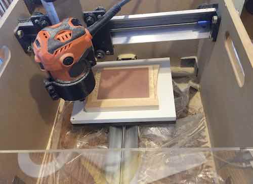
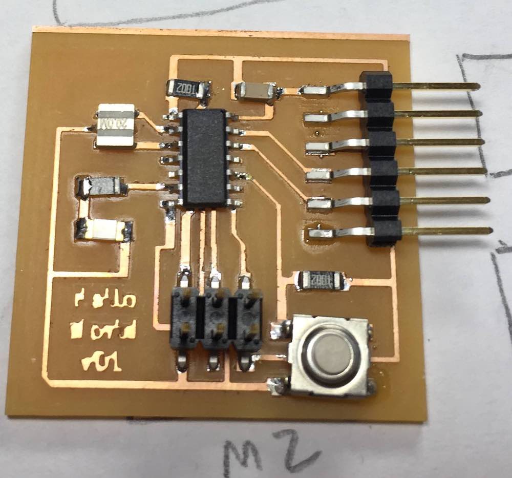
The final step was to mill a pocket sized for the PCB. The figure above shows the PCB in the pocket. I used XFasten double sided carpet tape to fix the PCB to the spoil board.
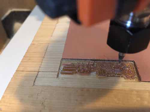
I was scared to jog the 1/64" bit to zero the z-axis. When using this end mill, I loosened the end mill in the collet, then jogged the router to the desired z-0 position, and then tightened the end mill in the collet. (This idea came from the MIT video showing how to mill a PCB.) The PCB is slightly thicker than 1mm. When I generated the first trace cuts, I failed to update the cut depth. This resulted in a cut that almost cut through the copper board.
The figure above shows several different traces cut on the copper board to test cut depth. I initially tried a .4mm cut. Next I tried .1 mm and found that mill only cut part of the trace. I increased the cut depth by 0.1mm and tried several more cuts. 0.4 mm was the first cut depth that resulted in a complete set of traces. The double sided tape may have a slightly inconsistent thickness, which resulted in slightly different cut depths across the board.
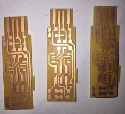
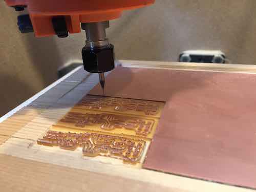
Here is my PCB Hero Shot showing several milled boards.
Populate the SMD Components
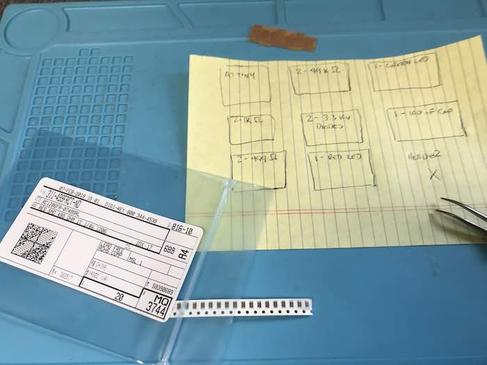
I have only done SMB work twice before. With both of those activities, it was suggested to organize the components before populating the board. My vision is not great for small parts, this this helps to get the right part in the right place on the board.
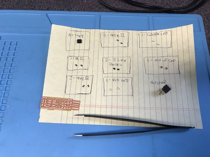
Here are the parts placed on the mat and ready for placement on the PCB.
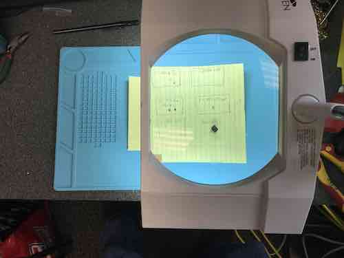
I used the magnifying glass when placing the parts on the PCB. This was also needed to find the stripes on the diodes and to get the right orientation of the LEDs.
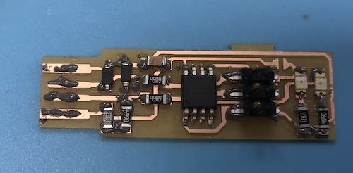
Next I added solder paste to the pads on the PCB. After that, I positioned the components on the board. The figure above shows the populated board after adding solder paste just before putting the board in the oven.
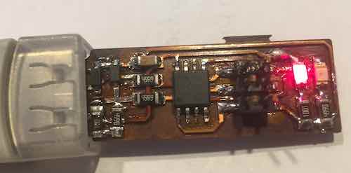
The figure above shows the finished board attached to 5V power supply with the red LED illuminated. I have used this reflow oven in the past, but the previous settings seems to have baked the board a little more than needed. There were no obvious bridges, but I cleaned up the traces a litte. The picture may not show this, but all the solder points appear shiny, so I don't think there are any cold joints. I used my multi-meter to check connectivity and validate that there were not shorts. Last I plugged the board into a USB extenstion and validated that the red LED lit.
Check if you can program it
I am using a Mac, so the next step was to install CrossPack. After installing CrossPack and the xcode command line tools, I downloaded the firmware source code and ran the make command.
petes-Air-7:fts_firmware_bdm_v1 pete$ make
avr-gcc -mmcu=attiny45 -Wall -DF_CPU=16500000UL -I. -funsigned-char -funsigned-bitfields -fpack-struct -fshort-enums -Os -Iusbdrv -c main.c -o main.o
main.c:109:13: warning: always_inline function might not be inlinable [-Wattributes]
 static void delay ( void )
             ^
avr-gcc -mmcu=attiny45 -Wall -DF_CPU=16500000UL -I. -funsigned-char -funsigned-bitfields -fpack-struct -fshort-enums -Os -Iusbdrv -c usbdrv/usbdrv.c -o usbdrv/usbdrv.o
avr-gcc -mmcu=attiny45 -Wall -DF_CPU=16500000UL -I. -funsigned-char -funsigned-bitfields -fpack-struct -fshort-enums -Os -Iusbdrv -c usbdrv/oddebug.c -o usbdrv/oddebug.o
avr-gcc -x assembler-with-cpp -mmcu=attiny45 -Wall -DF_CPU=16500000UL -I. -funsigned-char -funsigned-bitfields -fpack-struct -fshort-enums -Os -Iusbdrv -c usbdrv/usbdrvasm.S -o usbdrv/usbdrvasm.o
avr-gcc -mmcu=attiny45 -o fts_firmware.elf main.o usbdrv/usbdrv.o usbdrv/oddebug.o usbdrv/usbdrvasm.o
avr-size -C --mcu=attiny45 fts_firmware.elf
AVR Memory Usage
----------------
Device: attiny45

Program:    2488 bytes (60.7% Full)
(.text + .data + .bootloader)

Data:         75 bytes (29.3% Full)
(.data + .bss + .noinit)


avr-objcopy -j .text -j .data -O ihex fts_firmware.elf fts_firmware.hex
petes-Air-7:fts_firmware_bdm_v1 pete$ ls
Makefile		main.c			usbdrv
fts_firmware.elf	main.o
fts_firmware.hex	usbconfig.h
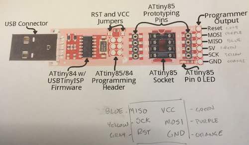
Next, step was to connect my existing programmer to the Fab board. I am using the Sparkfun Tiny Programmer. I added the SPI pins for the programmer output. Next I jumpered these pins to the ICMP pins on the Fab Board.
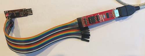
Next, "make flash" was run to flash the AT Tiny. The yellow communication LED lit as expected showing the handshake. Here is the transcript:
petes-Air-7:fts_firmware_bdm_v1 pete$ make flash
avrdude -p attiny45 -c usbtiny -P usb -e \
		-U flash:w:fts_firmware.hex

avrdude: AVR device initialized and ready to accept instructions

Reading | ################################################## | 100% 0.00s

avrdude: Device signature = 0x1e9206
avrdude: erasing chip
avrdude: reading input file "fts_firmware.hex"
avrdude: input file fts_firmware.hex auto detected as Intel Hex
avrdude: writing flash (2488 bytes):

Writing | ################################################## | 100% 2.53s

avrdude: 2488 bytes of flash written
avrdude: verifying flash memory against fts_firmware.hex:
avrdude: load data flash data from input file fts_firmware.hex:
avrdude: input file fts_firmware.hex auto detected as Intel Hex
avrdude: input file fts_firmware.hex contains 2488 bytes
avrdude: reading on-chip flash data:

Reading | ################################################## | 100% 3.37s

avrdude: verifying ...
avrdude: 2488 bytes of flash verified

avrdude: safemode: Fuses OK (H:FF, E:DF, L:62)

avrdude done.  Thank you.
Next, the "make fuses" command was run. Here is the transcript:
petes-Air-7:fts_firmware_bdm_v1 pete$ make fuses
avrdude -p attiny45 -c usbtiny -P usb \
		-U lfuse:w:0xE1:m -U hfuse:w:0xDD:m \
		-U efuse:w:0xFF:m

avrdude: AVR device initialized and ready to accept instructions

Reading | ################################################## | 100% 0.00s

avrdude: Device signature = 0x1e9206
avrdude: reading input file "0xE1"
avrdude: writing lfuse (1 bytes):

Writing | ################################################## | 100% 0.01s

avrdude: 1 bytes of lfuse written
avrdude: verifying lfuse memory against 0xE1:
avrdude: load data lfuse data from input file 0xE1:
avrdude: input file 0xE1 contains 1 bytes
avrdude: reading on-chip lfuse data:

Reading | ################################################## | 100% 0.00s

avrdude: verifying ...
avrdude: 1 bytes of lfuse verified
avrdude: reading input file "0xDD"
avrdude: writing hfuse (1 bytes):

Writing | ################################################## | 100% 0.01s

avrdude: 1 bytes of hfuse written
avrdude: verifying hfuse memory against 0xDD:
avrdude: load data hfuse data from input file 0xDD:
avrdude: input file 0xDD contains 1 bytes
avrdude: reading on-chip hfuse data:

Reading | ################################################## | 100% 0.00s

avrdude: verifying ...
avrdude: 1 bytes of hfuse verified
avrdude: reading input file "0xFF"
avrdude: writing efuse (1 bytes):

Writing | ################################################## | 100% 0.00s

avrdude: 1 bytes of efuse written
avrdude: verifying efuse memory against 0xFF:
avrdude: load data efuse data from input file 0xFF:
avrdude: input file 0xFF contains 1 bytes
avrdude: reading on-chip efuse data:

Reading | ################################################## | 100% 0.00s

avrdude: verifying ...
avrdude: 1 bytes of efuse verified

avrdude: safemode: Fuses OK (H:FF, E:DD, L:E1)

avrdude done.  Thank you.
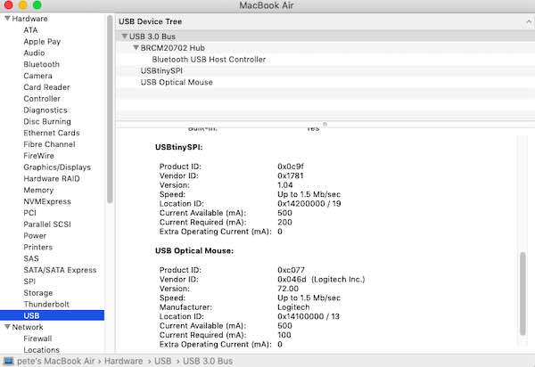
Next, I unplugged the ICMP pins and plugged the Fab Board into the Mac. Here is the screen shot that shows that it appears.
The last step was to Blow the Fuse using the "make rstdisbl" command and desolder the jumper. Here is the transcript:
petes-Air-7:fts_firmware_bdm_v1 pete$ make rstdisbl
avrdude -p attiny45 -c usbtiny -P usb \
		-U lfuse:w:0xE1:m -U hfuse:w:0x5D:m \
		-U efuse:w:0xFF:m

avrdude: AVR device initialized and ready to accept instructions

Reading | ################################################## | 100% 0.00s

avrdude: Device signature = 0x1e9206
avrdude: reading input file "0xE1"
avrdude: writing lfuse (1 bytes):

Writing | ################################################## | 100% 0.00s

avrdude: 1 bytes of lfuse written
avrdude: verifying lfuse memory against 0xE1:
avrdude: load data lfuse data from input file 0xE1:
avrdude: input file 0xE1 contains 1 bytes
avrdude: reading on-chip lfuse data:

Reading | ################################################## | 100% 0.00s

avrdude: verifying ...
avrdude: 1 bytes of lfuse verified
avrdude: reading input file "0x5D"
avrdude: writing hfuse (1 bytes):

Writing | ################################################## | 100% 0.01s

avrdude: 1 bytes of hfuse written
avrdude: verifying hfuse memory against 0x5D:
avrdude: load data hfuse data from input file 0x5D:
avrdude: input file 0x5D contains 1 bytes
avrdude: reading on-chip hfuse data:

Reading | ################################################## | 100% 0.00s

avrdude: verifying ...
avrdude: 1 bytes of hfuse verified
avrdude: reading input file "0xFF"
avrdude: writing efuse (1 bytes):

Writing | ################################################## | 100% 0.00s

avrdude: 1 bytes of efuse written
avrdude: verifying efuse memory against 0xFF:
avrdude: load data efuse data from input file 0xFF:
avrdude: input file 0xFF contains 1 bytes
avrdude: reading on-chip efuse data:

Reading | ################################################## | 100% 0.00s

avrdude: verifying ...
avrdude: 1 bytes of efuse verified

avrdude: safemode: Fuses OK (H:FF, E:5D, L:E1)

avrdude done.  Thank you.
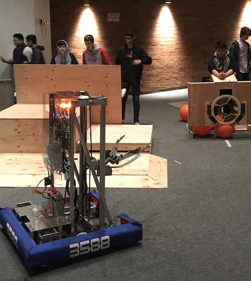
Today (2/19/2019) is the "bag and tag" day for the FIRST Robotics team. It is the final day of the build season. Here is a picture of the 2019 robot and team 3588.

Related Projects