Final Project: Pumpkin CNC Lathe
Project Description
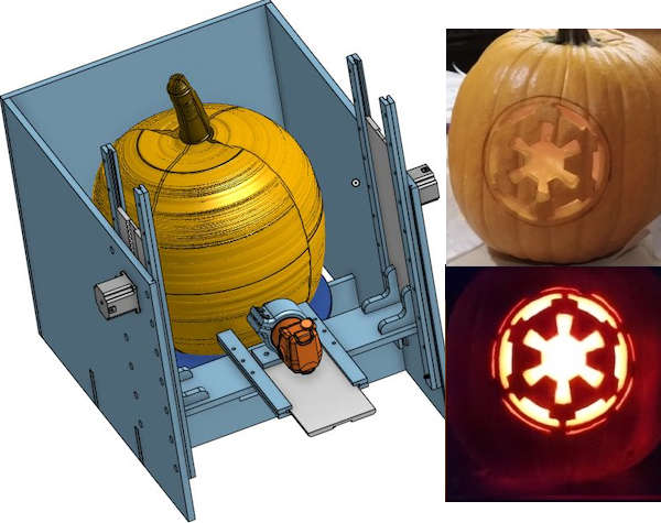
Create a CNC lathe that can machine a 2D drawing mapped onto an 3D irregular sphere
Assignment Details
- Individual assignment:
- Your project should incorporate 2D and 3D design, additive and subtractive fabrication processes, electronics design and production, microcontroller interfacing and programming, system integration and packaging
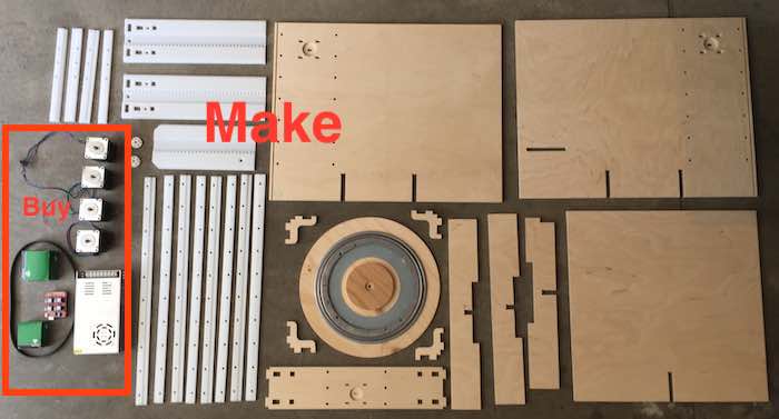
- Where possible, you should make rather than buy the parts of your project
- Projects can be separate or joint, but need to show individual mastery of the skills, and be independently operable
The final project video is shown below:
.
This is the summary slide
What will it do?
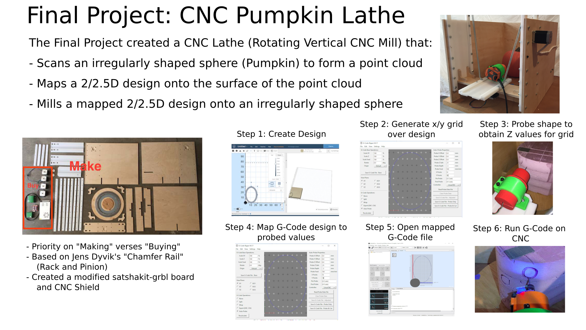
The final project is to create a CNC Lathe that can mill a 2D design onto irregularly shaped sphere (Pumpkin), based on mapping the 2D design onto a point cloud scanned from the target object in four (possibly five) iterations:
- Iteration 1: Build a vertical oriented CNC lathe
- Iteration 2: Move the steppers based on a jog controller
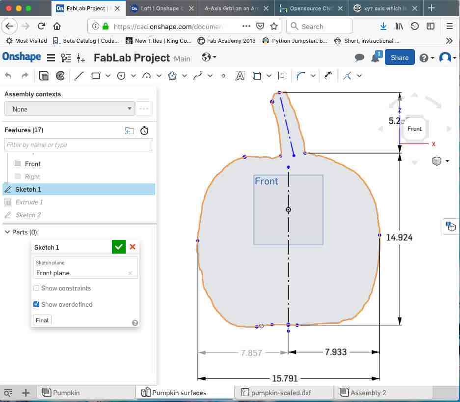
- Iteration 3: Use the CNC lathe to create a point cloud from probing the target object shape
- Iteration 4: Map a 2D drawing to 3D tool paths (Up/Down, In/Out, Rotation) based on the probed point cloud
- "Stretch" goal: Be able to able to vary the cut wall thickness to adjust transmitted light (Lithophane) or create 3D shapes on the pumpkin wall

Who's done what beforehand?
What have I done beforehand?
For the past several years, I have used my Laser Cutter/Engraver to etch a drawing onto pumpkins. This requires wearing special eye protection and venting the fumes.
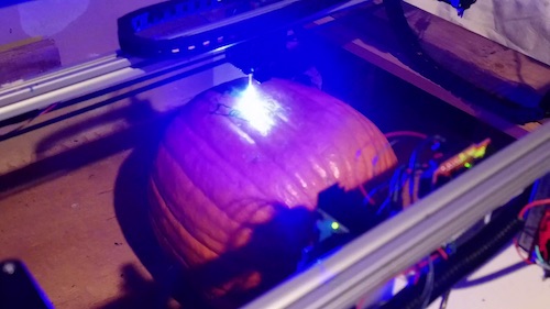
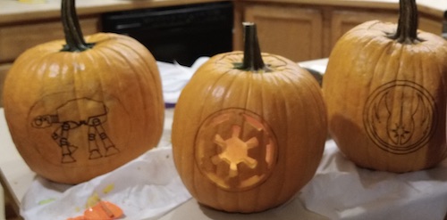
My laser is not strong enough to cut, so the best that it can do is to etch a line. The darkness of the etching varies based on the distance from the laser's focal point. Additional work needs to be done after etching to carve the pumpkin using the etched lines. The goal of the project is to have a "finished" pumpkin when the process completes.

What have others done beforehand?
Here are some previous projects and what applies or does not apply to my problem:
CNCs
- Much of the design is based on the rack and pinion and axis motion from previous year’s CNC designs. There seem to be two schools of thought for the MIT/Fab Academy CNC designs. One led by Jens Dyvik's "Chamfer Rail", uses a rack and pinion with a beveled side sliding in a low friction face to face joint. The other led by Jake Reed, nominally called RCT (Roller Coaster Bearing) uses a timing belt over a toothed pulley to move the gantry back and forth. Roller coaster bearings are used to manage the friction.
- My design leverages the large tooth profile from the rack and pinion design. In previous designs the rack is fixed and the pinch rails move with the gantry. In my design, the pinch rails are fixed and the rack moves with the gantry. Previous application of the rack and pinion designs have been primarily to x, y, z axis CNCs. The Hedy is a vertical mill, but I haven’t seen an application of the concept to a vertical lathe.
- CNC Machine a pumpkin There are a number of documented projects to cut pumpkins with a CNC, but most assume just X, Y, and Z not rotation around an axis and do not account for the irregular shape. Most of these projects do not take into account the actual curvature of the target object in the tool path. These previous approaches may not work for irregular shapes (gourds).
CNC Lathes
- This project extrudes chocolate onto a banana. Similar idea, but this project needs to cut the object being rotated.
- MIT additive lathe - This is a 3D printer onto a rotating spindle. Maybe able to use ideas for the chuck and rotational gearing, but additive and subtractive processes are different.
- Eggbot - There is an interesting Inkscape plug-in that may provide some ideas to map the 2D shape to 3D shape. The z axis seems to be spring activated touching the surface of the egg. My machine needs to vary the z axis cut depth based on the external shape of the object and how much light is intended to show.
Hardware and Software
This project is highly dependent on previous work on generation of tool paths in G-Code and execution of the G-Code using GRBL and CNC control using Universal G Code Sender (UGS).
- Generation of the initial tool paths from the 2D designs can be done with one of many Open Source G-Code generators such as Easel, Carbide Create, or Kiri:Moto. Each of these programs generate X, Y, Z tool paths that need to be converted to up/down, in/out, and rotation tool paths mapped onto the point cloud of the target object.
- GRBL is a G-Code interpreter that runs on a ATMega 328 type microcontroller. The ATMega 328 board drives a set of stepper motor drivers that move the stepper motors.
- The G-Code is sent to the ATMega 328 by a program running on a PC called Universal G Code Sender (UGS). UGS also has the ability to send individual jog commands or G-Code macros to the microcontroller.
- The point cloud generation is based on execution of a number of G38.2 probe commands in a script that rotates the object and moves the probe to touch points on the outside of the target shape. Each line in the script is issued from UGS and executes a command to move the probe until it touches the target object surface closing a limit switch which completes a circuit and stops the movement. The G-Code coordinates are then passed back from UGS as a set of JSON parameters. These points form the point cloud for the target object.
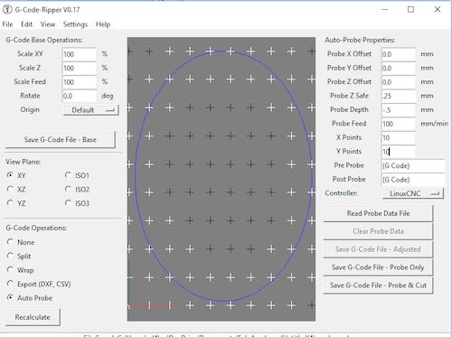
- The combination of the point cloud and the original G-code are loaded into a program such as G-Code Ripper from http://scorchworks.com which translates the tool paths based on the Point Cloud offsets. This creates the G-Code that is then executed on the target object.
Lithophane (if time remains)
I haven’t found any direct way to generate Lithophane tool paths from a design. Here are some early concepts, that I will explore if I have time.
- This video shows how to create a Lithophane in OpenSCAD.There could be elements that could be reused for 2D to 3D mapping and to determine the wall thickness based on transmitted light.
- This shows an approach to 2D to Cylinder mapping using OpenSCAD. This would have to be adapted from a cylinder to a sphere
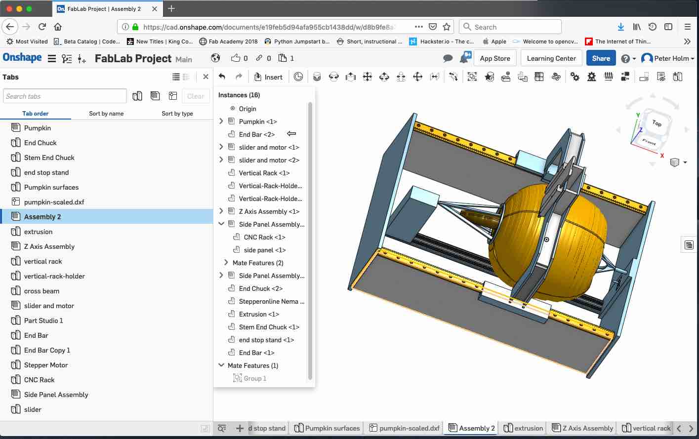
What did I design, what materials and components were used, where did they come from, how much did they cost, which parts and systems were made, what processes were used?
The figure shows a dynamic model of the final project. Move the left mouse button to rotate the assembly. Rotate the mouse button to zoom in or out.
- A mechanism to hold and rotate the irregularly shaped sphere
- Leverage the existing rack and pinion tooth design in up/down and in/out axis gantries
- A mechanism to hold the router on the in/out gantry
- A jog controller to move the steppers
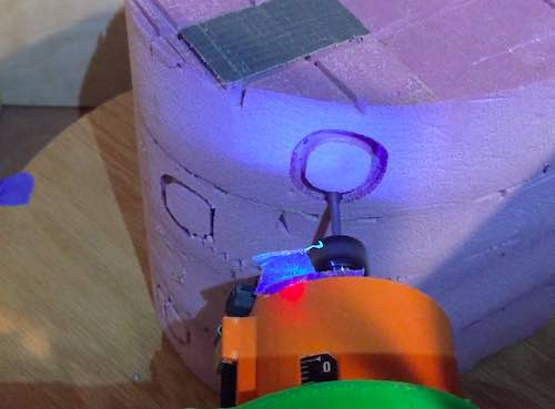
- A sensor probe that travels on the up/down axis and extends on the in/out axis to measure the perimeter of the irregularly shaped sphere
- PCB(s) for the ATMega 328 run GRBL and drive the stepper controllers
- Software to read the depth sensor and create a point model of the perimeter
- Adapt a software tool chain to map the 2D drawing to the 3D sphere and generate the machine commands to cut
Part Assembly Summary Tables
This section is organized by the assemblies that make up the project. The following figures and tables answer the following questions for each assembly:
- What materials and components were used?
- Where did they come from?
- How much did they cost?
- What parts and systems were made?
- What processes were used?
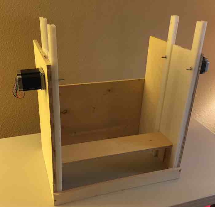
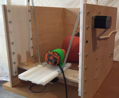
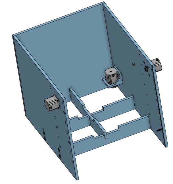
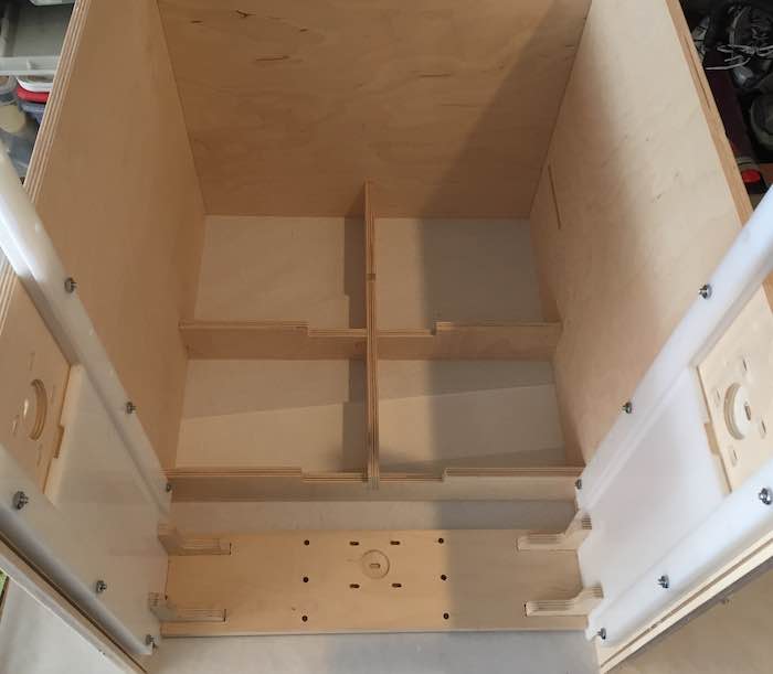
Case Assembly
The case is sized to fit the pumpkin that I laser cut last year. It is made from .5 in Baltic Birch with cross braces for stability.
| Item No. | Name | Quantity | Material | Source | Cost | Make/Buy | Process Used | Reference |
|---|---|---|---|---|---|---|---|---|
| 1 | Case Assembly | http://www.crosscuthardwoods.com/ | ||||||
| 1.1 | Case - Right Side | 1 | 1/2” Plywood | Crosscut Hardwoods | *1 | Make | Large CNC | http://www.crosscuthardwoods.com/ |
| 1.2 | Case - Left Side | 1 | 1/2” Plywood | Crosscut Hardwoods | *1 | Make | Large CNC | http://www.crosscuthardwoods.com/ |
| 1.3 | Case - Back Side | 1 | 1/2” Plywood | Crosscut Hardwoods | *1 | Make | Large CNC | http://www.crosscuthardwoods.com/ |
| 1.4 | Case - bottom support | 2 | 1/2” Plywood | Crosscut Hardwoods | *1 | Make | Large CNC | http://www.crosscuthardwoods.com/ |
| 1.5 | Case - cross support | 1 | 1/2” Plywood | Crosscut Hardwoods | *1 | Make | Large CNC | http://www.crosscuthardwoods.com/ |
| 1.6 | rotating axis motor bracket | 1 | PLA Filliment | *2 | Make | 3D Print | ||
| 1.7 | large pinion 60 circ v2 | 2 | 1/2” HPDE | Tap Plastics | *3 | Small CNC | https://www.tapplastics.com/product/plastics/cut_to_size_plastic/hdpe_cutting_boards/346 | |
| 1.8 | NEMA23 Stepper - 270 in-oz (57BYGHH627) | 3 | Wantai Motor - eBay via Makerspace Order | $20 / ea | Buy |
*1 - 5' x 5' Russian Birch Plywood - $50. *2 - PLA 3D Printer filament - $20 *3 - 6" x 6" x .5" HPDE - $10
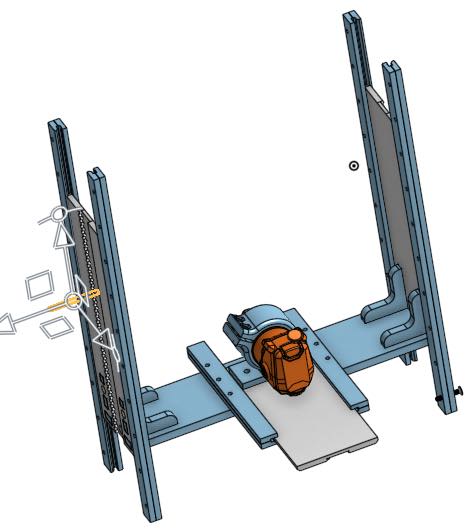
Gantry Assembly
The gantry moves up and down on an HDPE rack and pinion system and holds a router which moves in and out on a similar rack and pinion system.
| Item No. | Name | Quantity | Material | Source | Cost | Make/Buy | Process Used | Reference |
|---|---|---|---|---|---|---|---|---|
| 2 | Gantry Assembly | |||||||
| 2.1 | Up/Down Rack Assembly | 1 | Make | Large CNC | ||||
| 2.1.1 | innerRailBrace | 4 | 3/8” HPDE | Tap Plastics | *4 | Make | Large CNC | https://www.tapplastics.com/product/plastics/cut_to_size_plastic/hdpe_sheets/529 |
| 2.1.2 | outerRailBrace | 4 | 3/8” HPDE | Tap Plastics | *4 | Make | Large CNC | https://www.tapplastics.com/product/plastics/cut_to_size_plastic/hdpe_sheets/529 |
| 2.1.3 | 15.5 in Rack - Right | 1 | 3/8” HPDE | Tap Plastics | *4 | Make | Large CNC | https://www.tapplastics.com/product/plastics/cut_to_size_plastic/hdpe_sheets/529 |
| 2.1.4 | 15.5 Rack - Left | 1 | 3/8” HPDE | Tap Plastics | *4 | Make | Large CNC | https://www.tapplastics.com/product/plastics/cut_to_size_plastic/hdpe_sheets/529 |
| 2.2 | Gantry Cross Bracket | 1 | 1/2” Plywood | Crosscut Hardwoods | *1 | Make | Large CNC | http://www.crosscuthardwoods.com/ |
| 2.3 | Corner Bracket | 4 | 1/2” Plywood | Crosscut Hardwoods | *1 | Make | Large CNC | http://www.crosscuthardwoods.com/ |
| 2.4 | In/Out Rack Assembly | 1 | ||||||
| 2.4.1 | left - short inner brace | 1 | 3/8” HPDE | Tap Plastics | *4 | Make | Large CNC | https://www.tapplastics.com/product/plastics/cut_to_size_plastic/hdpe_sheets/529 |
| 2.4.2 | left - short outer brace | 1 | 3/8” HPDE | Tap Plastics | *4 | Make | Large CNC | https://www.tapplastics.com/product/plastics/cut_to_size_plastic/hdpe_sheets/529 |
| 2.4.3 | right - short outer brace | 1 | 3/8” HPDE | Tap Plastics | *4 | Make | Large CNC | https://www.tapplastics.com/product/plastics/cut_to_size_plastic/hdpe_sheets/529 |
| 2.4.4 | right- short inner brace | 1 | 3/8” HPDE | Tap Plastics | *4 | Make | Large CNC | https://www.tapplastics.com/product/plastics/cut_to_size_plastic/hdpe_sheets/529 |
| 2.4.5 | 11 in Rack | 1 | 3/8” HPDE | Tap Plastics | *4 | Make | Large CNC | https://www.tapplastics.com/product/plastics/cut_to_size_plastic/hdpe_sheets/529 |
| 2.4.6 | Router Bracket | 1 | PLA Filliment | Make | 3D Print | |||
| 2.4.7 | NEMA23 Stepper - 270 in-oz (57BYGHH627) | 1 | Wantai Motor - eBay | $20 / ea | Buy |
*4 - 2" x 3" x .375" HPDE - $60
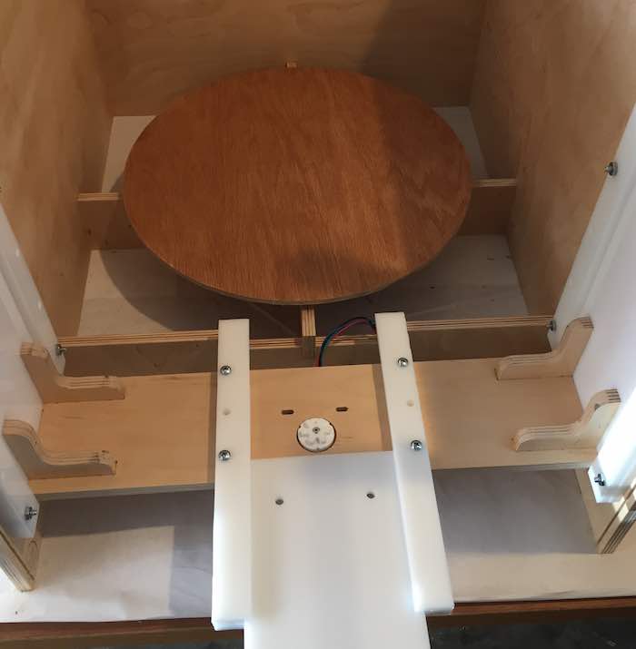
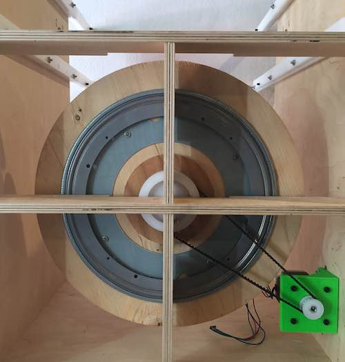
Rotating Axis Base Assembly
The base rotates using two pulleys and a timing belt attached to a stepper motor. The weight is taken by a lazy susan bearing. The size force of the pulley is applied against a 5/8 bolt sitting loosely in a holes in the center of the base and the cross pieces.
| Item No. | Name | Quantity | Material | Source | Cost | Make/Buy | Process Used | Reference |
|---|---|---|---|---|---|---|---|---|
| 3 | Rotating Axis Base Assembly | 1 | ||||||
| 3.1 | Lazy Susan Mount | 1 | 1/2” Plywood | Crosscut Hardwoods | *1 | Make | Large CNC | http://www.crosscuthardwoods.com/ |
| 3.2 | Rotating Base | 1 | 1/2” Plywood | Crosscut Hardwoods | *1 | Make | Large CNC | http://www.crosscuthardwoods.com/ |
| 3.3 | "12"" Round Lazy Susan - 28985" | Rockler Woodworking and Hardware | $10.00 | Buy | ||||
| 3.4 | "1/2” Wd. .375 Pitch, L Series Timing Belt" | 1 | $15.00 | Buy | https://www.mcmaster.com/timing-belts |
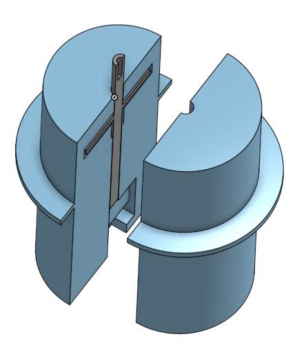
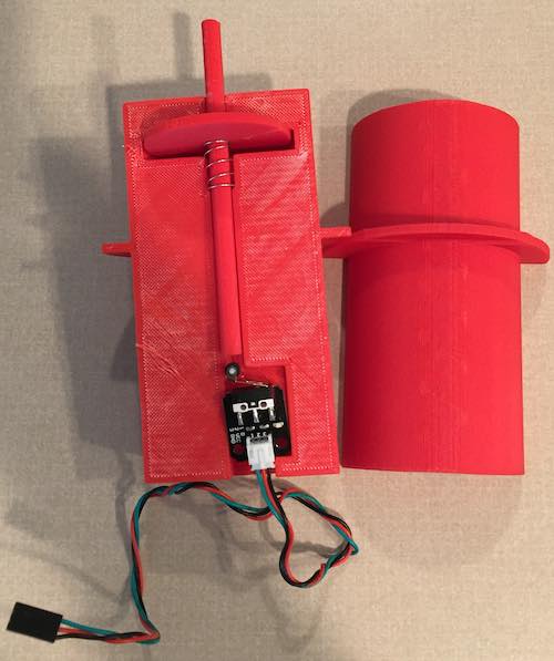
Probe Assembly
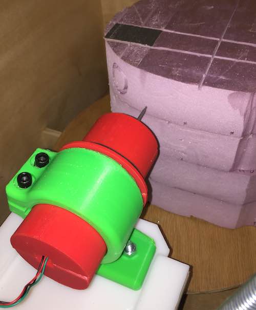
The probe assembly is used to stop the G38.2 command. It consists of 4 3D printed halves of a plunger and cylinder pressing on a limit switch. The probe fits in the router bracket housing.
| Item No. | Name | Quantity | Material | Source | Cost | Make/Buy | Process Used | Reference |
|---|---|---|---|---|---|---|---|---|
| 4 | Probe Assembly | |||||||
| 4.1 | Probe Housing | PLA Filliment | *2 | Make | 3D Print | |||
| 4.2 | Probe | 1/16 Metal Rod | Buy | |||||
| 4.3 | Limit Switch | Scrap Materials from Makerspace | Free | Acquire |
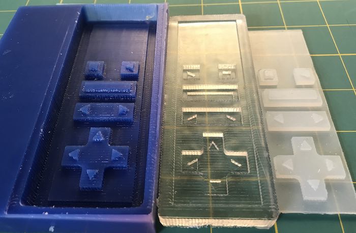
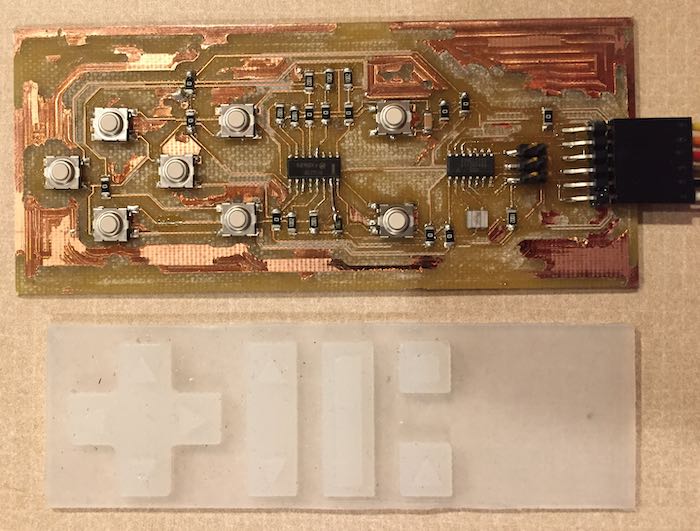
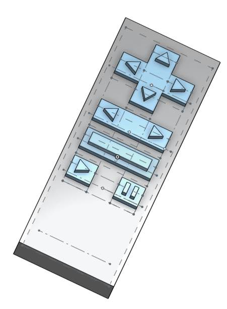
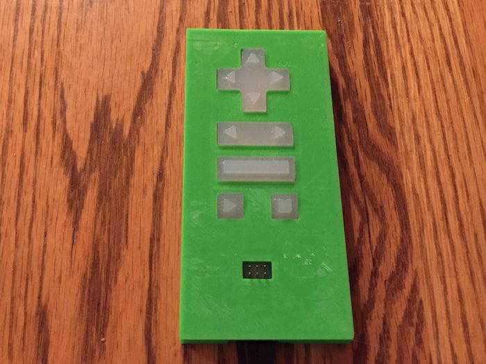
Jog Controller Assembly
The Jog Controller was done over several week's assignments. The silicone was cast in Moulding And Casting. The Electronics were built in Input Devices. The software was written in Interface and Application Programming.
| Item No. | Name | Quantity | Material | Source | Cost | Make/Buy | Process Used | Reference |
|---|---|---|---|---|---|---|---|---|
| 5 | Jog Controller Assembly | |||||||
| 5.1 | Silicone button casting | Free | Acquire | |||||
| 5.2 | Jog Controller PCB | Make | PCB CNC | |||||
| 5.3 | Jog Controller Case | PLA Filliment | *2 | Make | 3D Print |
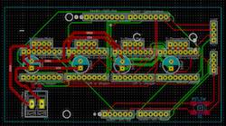
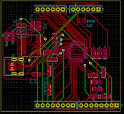
Electronics
The electronics consist of two boards. One is a modified version of the Satshakit Serial board and the other is a modified version of a CNC Shield to drive DRV8825 drivers.
| Item No. | Name | Quantity | Material | Source | Cost | Make/Buy | Process Used | Reference |
|---|---|---|---|---|---|---|---|---|
| 6 | Electronics | |||||||
| 6.1 | 24v 15a DC Universal Regulated Switching Power Supply | EAGWELL (amazon.com) | $24.68 | Buy | https://www.amazon.com/EAGWELL-Universal-Regulated-Switching-Computer/dp/B01IOK5FM0/ref=cm_cr_arp_d_product_top?ie=UTF8 | |||
| 6.2 | PCB Assembly | |||||||
| 6.2.1 | GRBL board | Make | PCB CNC | |||||
| 6.2.2 | Stepper Motor driver shield | Make | PCB CNC | |||||
| 6.2.3 | DRV 8255 - Stepper Motor Driver | Scrap Materials from Makerspace | Acquire |
What questions were answered?
My questions were related to risks associated with unknowns
- Could I make stepper motors move with grbl - risk: low
- This was a low risk because I have built a Laser cutter and a small CNC in the past.
- Could I leverage the rack and pinion system from previous in a vertical rotating mill - Risk: medium
- My previous CNC machines used belts or lead screws, so the rack and pinion approach was new. I also have not designed or built a rotating system.
- Would the torque associated with the stepper motor selection be enough to mill selected objects - Risk: medium
- My previous project have used low torque NEMA 17 steppers. I have not used higher torque motors such as NEMA 23 steppers. I found that using 2 steppers to lift the gantry provided enough torque, but friction would not hold the gantry in place when power was removed from the motors. There were two solutions to this problem. One was to set the timeout for the motors so that power was not removed from the motors after movement stopped. I found that this caused the stepper motor drivers to get pretty hot, so I decided to offset the weight of the gantry with a set of springs. Given the Kx spring force formula, there is less force at the top when x is small and more at the bottom when x is larger. The spring force was adjusted to keep the gantry in place at the top of the cutting volume while not providing too much force at the bottom of the bottom of the cutting volume. This took some tuning.
- Could the G-Code 38.2 command be used to create a point cloud from probing a selected object - Risk: High
- When I started the class, I was not aware of G38.2. I found the command as part of my research on what had been do to zero the Z axis on a CNC. Higher end CNCs provide a puck that can be placed on the surface of the material to be milled which is touched by the end mill to electrically complete a circuit. Movement stops when the circuit is closed. This is used to set the z axis to zero (the end location - the height of the puck). This was not exactly what I needed because I needed a set of points, not just one for an axis reset. I designed a 3D Printed Probe assembly that fit in the housing for the router bracket. The center of the probe matched the center of the end mill. There is also a slot in the probe to hold an .125 in end mill. After the point cloud is generated and applied to the g-code, the mill is manually jogged until the end mill just touches the pumpkin and the z axis is manually set to 0.
- How much existing software could be leveraged, verses needing new development - Risk: High
- There were two large breakthroughs that enabled the success of this project. These were both discoveries that enabled me to stand on shoulders not on toes. One was discovering that Universal G Code sender supported a REST interface. As part of the molding & casting weeks, inputs and application programming, I needed to find a way to remotely invoke G-Code commands. The REST interface allowed me to be able to write a Python HTTP client to send the commands as input to UGS which in turn would send the associated G-Code to GRBL running on the PCB. I used jog commands to move the CNC, but raw G-Code such as G38.2 could also be send. I expected that the response to the G38.2 command would be the coordinates of where the probe stopped. I found that the commands where asynchronous, so nothing was returned. I had to rely on sending a second status command which returned the current coordinates. The trick was to wait after the G38.2 was sent for the probe to hit the object and sending the getStatus command twice and comparing the coordinates. If the coordinates didn't change, then the probe has hit the object. If the coordinates changed, then wait for more time. The coordinates that didn't change were used as the Z value for the given X and Y in the point cloud. The second breakthrough was the discovery of G-Code Ripper. This program provided the mapping of the 2/2.5D G-Code design onto the probed point cloud. This made the the entire process much simpler. Without this program, I would have had to write the transformation which would have been very hard.
How will it be evaluated?
The tool chain runs from CAD through CAM. There are several ways this could be done. This is an example of milling an oval.
First, a design is created. This can be done in an SVG tool such as Inkscape or if the design is simple, directly in a CAM tool such as Easel.
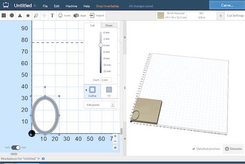
The CAM tool is used to generate G-Code. The G-Code is exported and imported into G-Code Ripper. This tool is used to generate the x/y grid of points to be scanned.
This grid is exported and used as input to a Python script that I wrote that reads the g-code 38.2 probe commands, sends them using REST to Universal G-Code Sender which then sends them to the CNC and moves the probe.
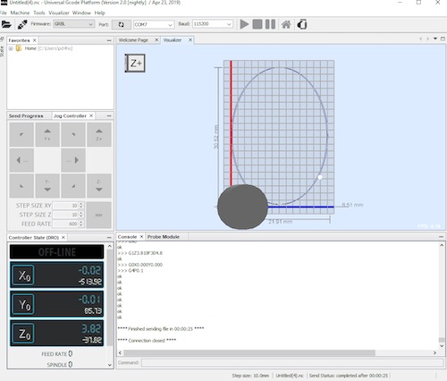
After each probe, a query is made for the current coordinates. This produces the Z value where the probe stopped. These x, y, z values are written to a file. This file is loaded back into G-Code ripper along with the original G-Code and used to map the design to the surface. Last the mapped G-Code is loaded into Universal G-Code Sender and executed on the CNC.
Ultimately, the final evaluation is "Will my wife allow me to put pumpkins created by the CNC on the front porch?"
What are the implications?
The real benefit of this activity is not the CNC, but the knowledge of how to build CNCs. I expect to build a larger x/y/z CNC as alternative to my smaller CNC. It is likely that I could build a vinyl / fabric cutter for my wife's quilting crafting. Bottom line is that this class did what was advertised, it helped me to learn how to build almost anything.
Misc Documentation
Earlier assignments covered building the jog controller assembly, and the CNC. This section covers creation of the electronics for the final project.
The main board is based on the satshakit-grbl board but a different UART. I couldn't source a CH340G USB to Serial converter from Digikey, so I substituted an FT232RL-REEL UART. It required some small changes to the wiring but it does the same thing with better driver support.
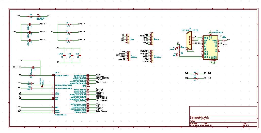
Because I wanted to drive my CNC shield, I rewired the headers to match the normal Arduino GRBL pin out.
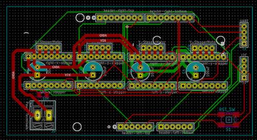
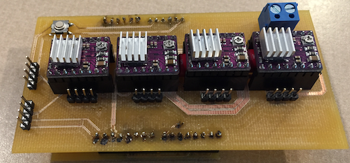
I am using the TI DRV8825 stepper drivers. I needed to build a shield to hold the drivers. The shield is based on the CNC shield.
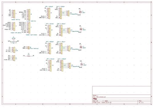
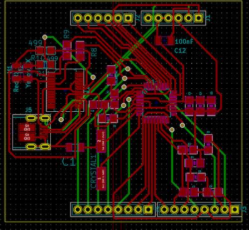
The traces that supported the steppers needed to handle up to 2 amps of current. The traces were widened for this reason.
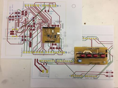
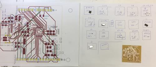
This picture shows the components ready to be placed on the milled board.
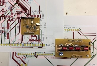
This picture shows the board after reflow.

This picture shows the two completed boards. (Note the DRV8825 drivers are not shown in this picture.)
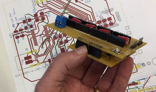
This picture shows the assembled base and shield.
Reference Files
- G-Code for Positive Mold
- Jog Controller Step file
- KiCAD archive file for the JogController project
- Arduino C code for the JogController
- Exported drawings, Aspire files, and G-Code
- Jog Controller Python Script
- KiCAD files for Satshakit serial modified to use FT232RL-REEL UART.
- KiCAD files for CNC Shield to drive DRV8825 drivers.
Related Projects