Description of Final Project
Aim - Dam Water Level Measurement through Sensors and Display on LED matrix
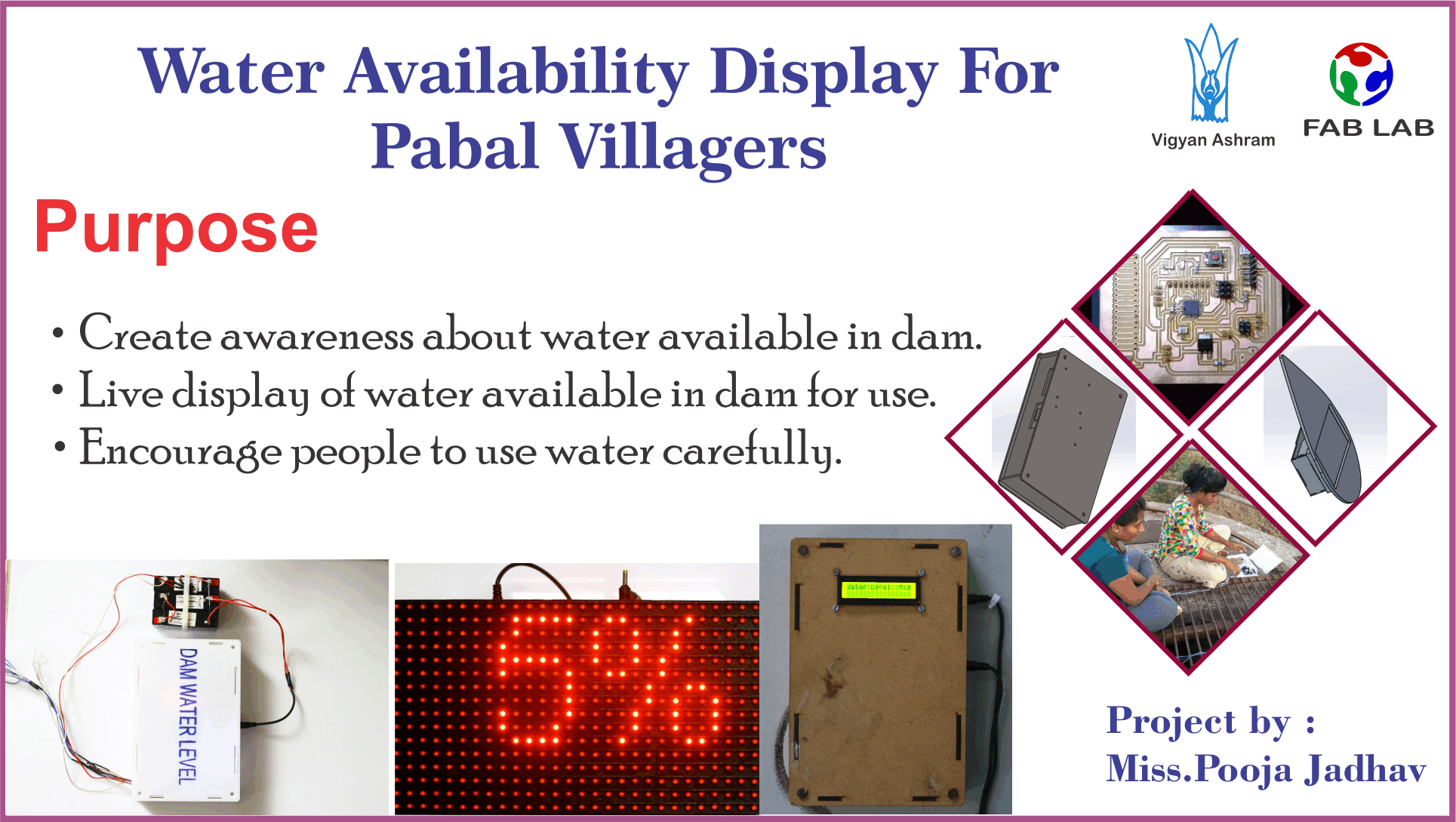
Water Avaibility Display for pabal Villagers.
Discussion on differnt Project idea
In Vigyan Ashram I got Different idea on different projects. I live in a rural area so I know water-related problems for the rural area. I discuss a different project idea of rural development like waste management, food Processing, water recycling with our Director Dr. Yogesh Kulkarni and I also discuss with our Deputy Director Mr. Ranjeet Shanbhag on advanced technology in Agriculture.
When I was discussing with sir, that time I Like the concept of Dam Water level Indicator. When People will see the display in their village, they know water storage in the dam and how should be used.So,I finalised this Project.
Need
Basically, I belong from a rural area. I have seen in the rural area that there is limited water storage due to lack of rain since last 23 years.do not have sufficient water still people do not use properly.so, I am going to make a device that has enough water reserves in the village dam and how much longer it can be used. and it shows on a 7 segment display. this display indicates the storage of water in the dam. People will see this display they will be aware that there is only enough water storage in our dam and we have to use water properly.
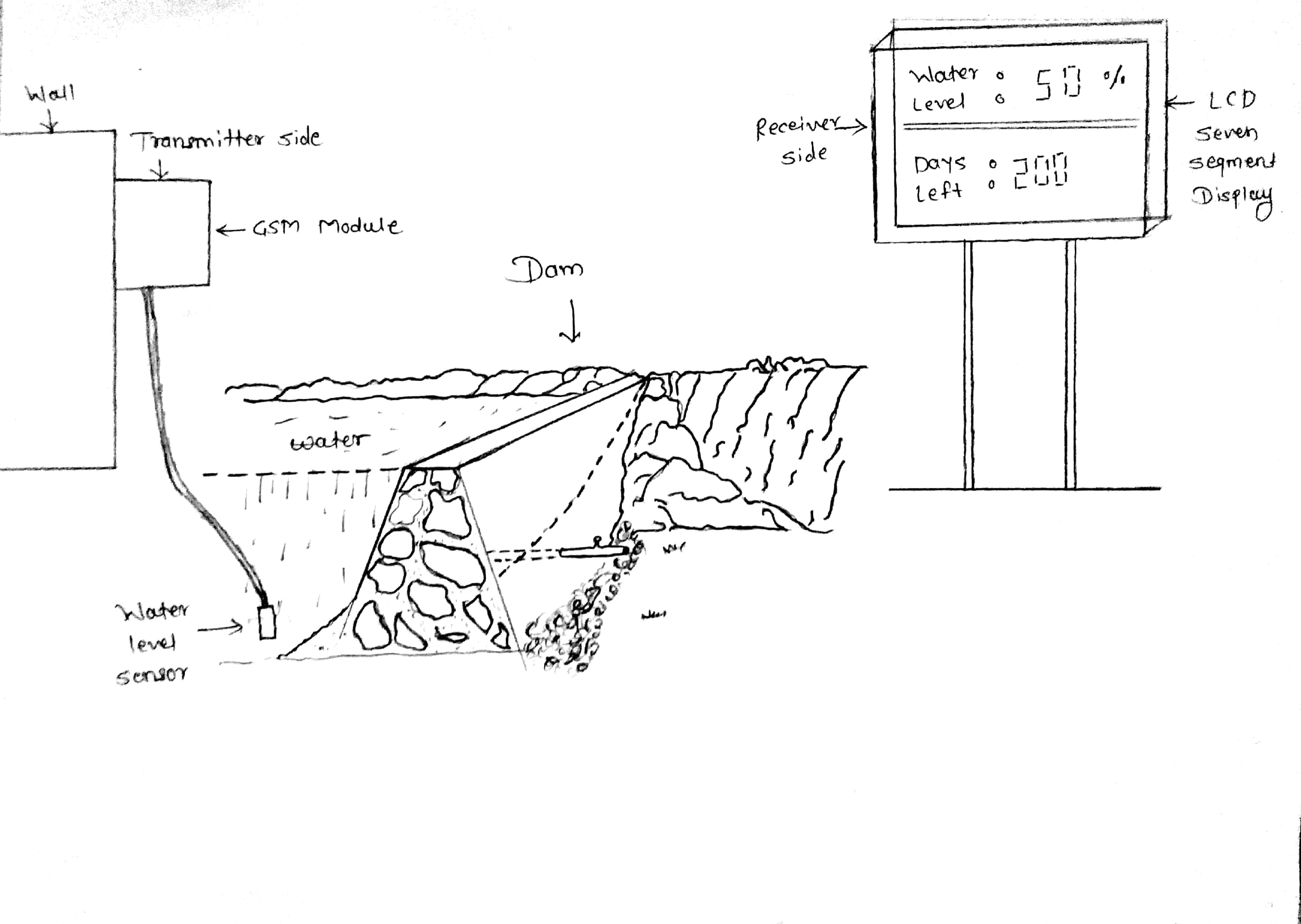
Sketch Of Final Project
Project idea in this week Principle and Practices
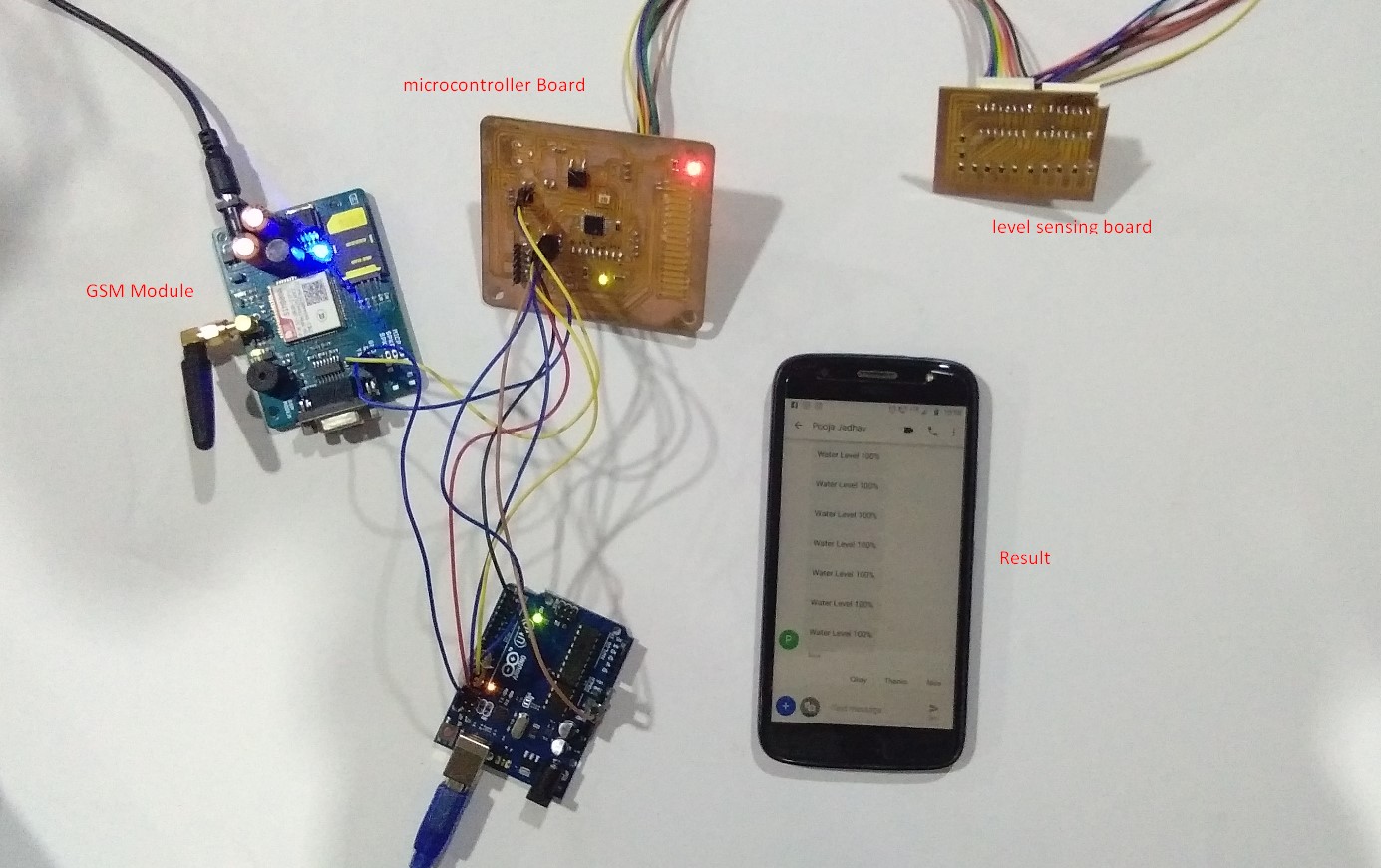
Working
- Water level Sensor senses a dam water level and sends reading to Microcontroller.
- Microcontroller send cammand to transmitter side GSM module. A send sms of water level value to receiver side GSM module.
- This sms is received in receiver side GSM module. This live sms send to a LED matrix display.
- A water level display on LED module.
- Atmega 328p
- 8 pin connector
- 4,3 and 2 pin connector
- LED
- Register 499 ohm
- Capacitor 10 microfarad
- 20mHz Resonator
- Suits displays with a HUB12 interface
- Pin spacing to suit Arduino compatible headers
- Connector for 10-way ribbon cable for DMD (not included)
- Arduino compatible library, graphics functions and example support
Block diagram of transmitter side

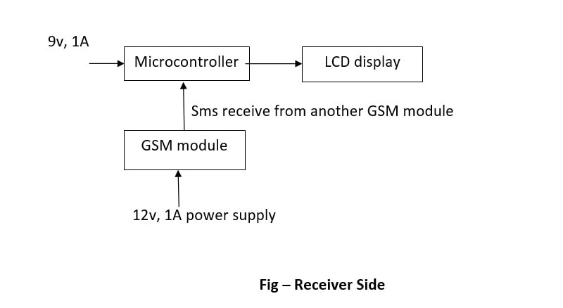
Block diagram of Receiver side
Solution
The Dam water level indicator is defined as a system which gets the information about the water level in Dam or reservoirs. which is used in cities and villages. By using the water level indicator we can overcome the overflow of water from the Dams.
Project Plan
I have also created a Gnatt chart for project management.It is a online tool with paid and free options.Project plan is very useful to do work on time, calculate the risk, manage the things or inventory and I made gantt chart for my project. Its a six months planning with dates but its very hard to keep with dates.
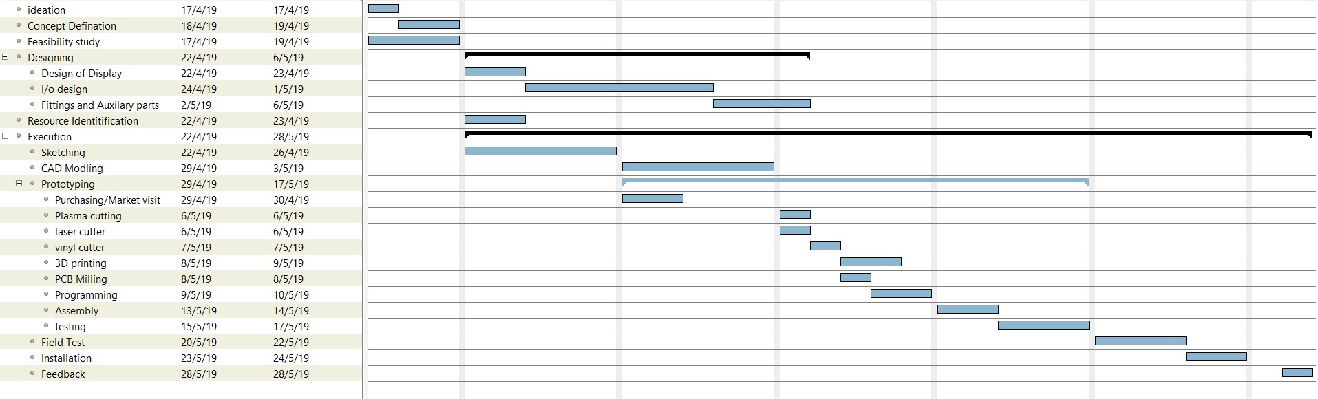
I made Planning Chart In this week Project Management
This is my project material list.
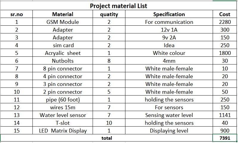
I made Project material list Application and Implication
Electronic
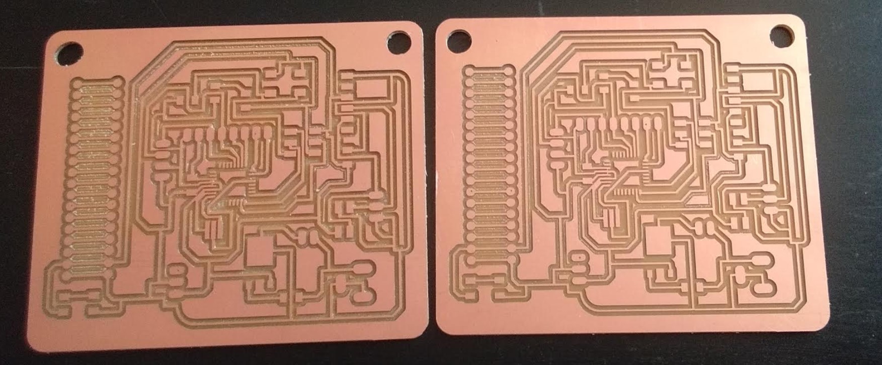
Design and Fabricate BoardUsing Eagle and Rolland SRM-20 milling machine, I made two PCB for sensing Water level sensor. And AT-mega 328 microcontroller Board.I want to measure water level in my project so I decided to make water level sensor in this assignment.
In water level sensor I need 5 connectors for checking level in different steps.So,I took 5 connectors (2 pins header),registors (In one circuit I took two registor) and 8 pin header for input(5 for inputs and 2 for GND and VCC). Firstly I arranged components and join it using jumper wires.then i checked erros.then I got a one error,I cleared it and clicked on switch board.
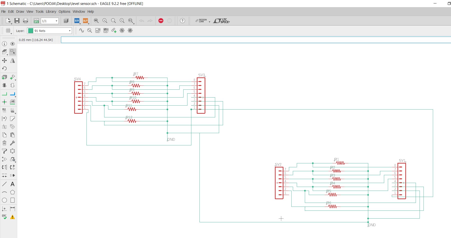
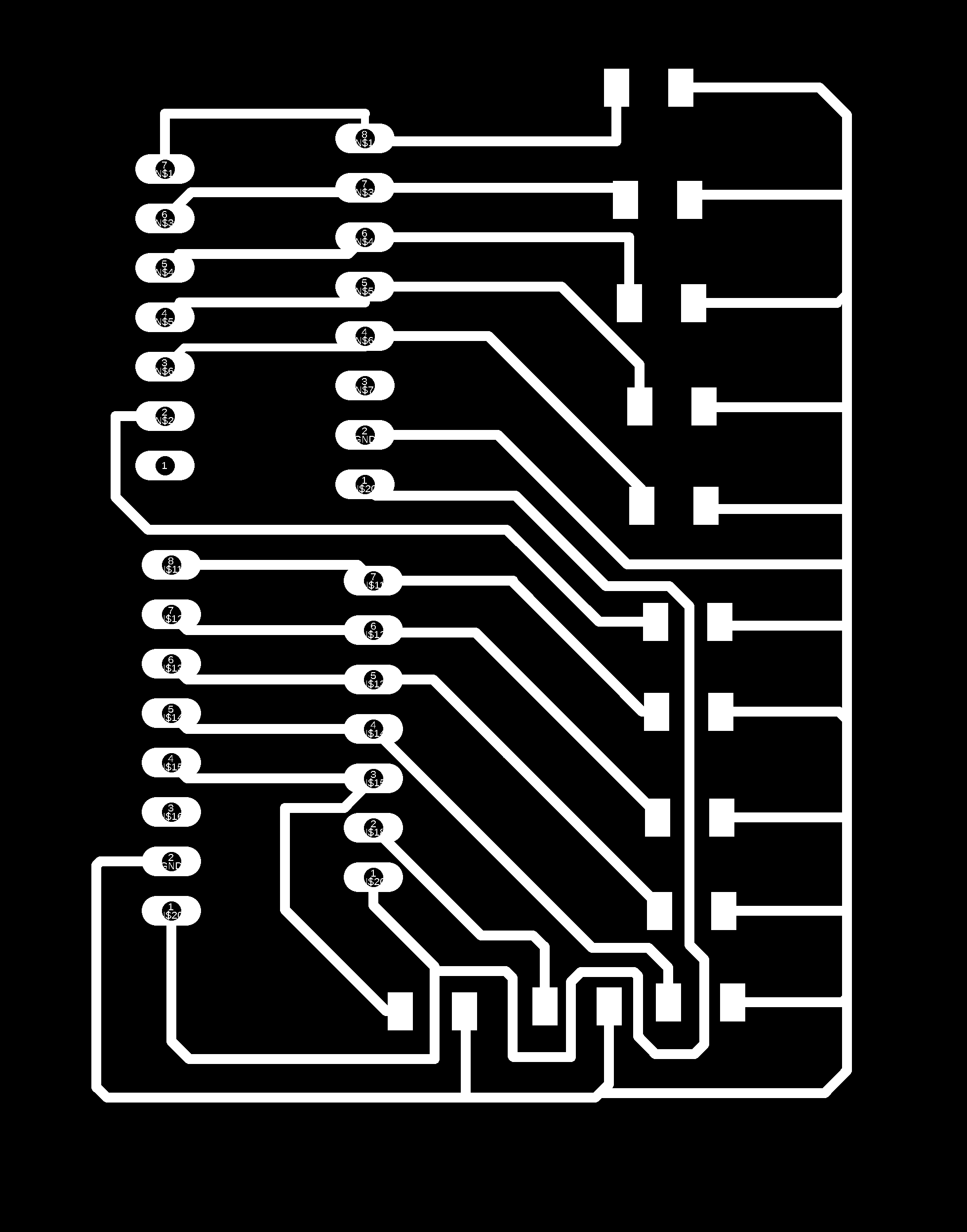
Then I routed my board and checked the DRC. Here routing is done.
And saved the board in .png format.
|
|
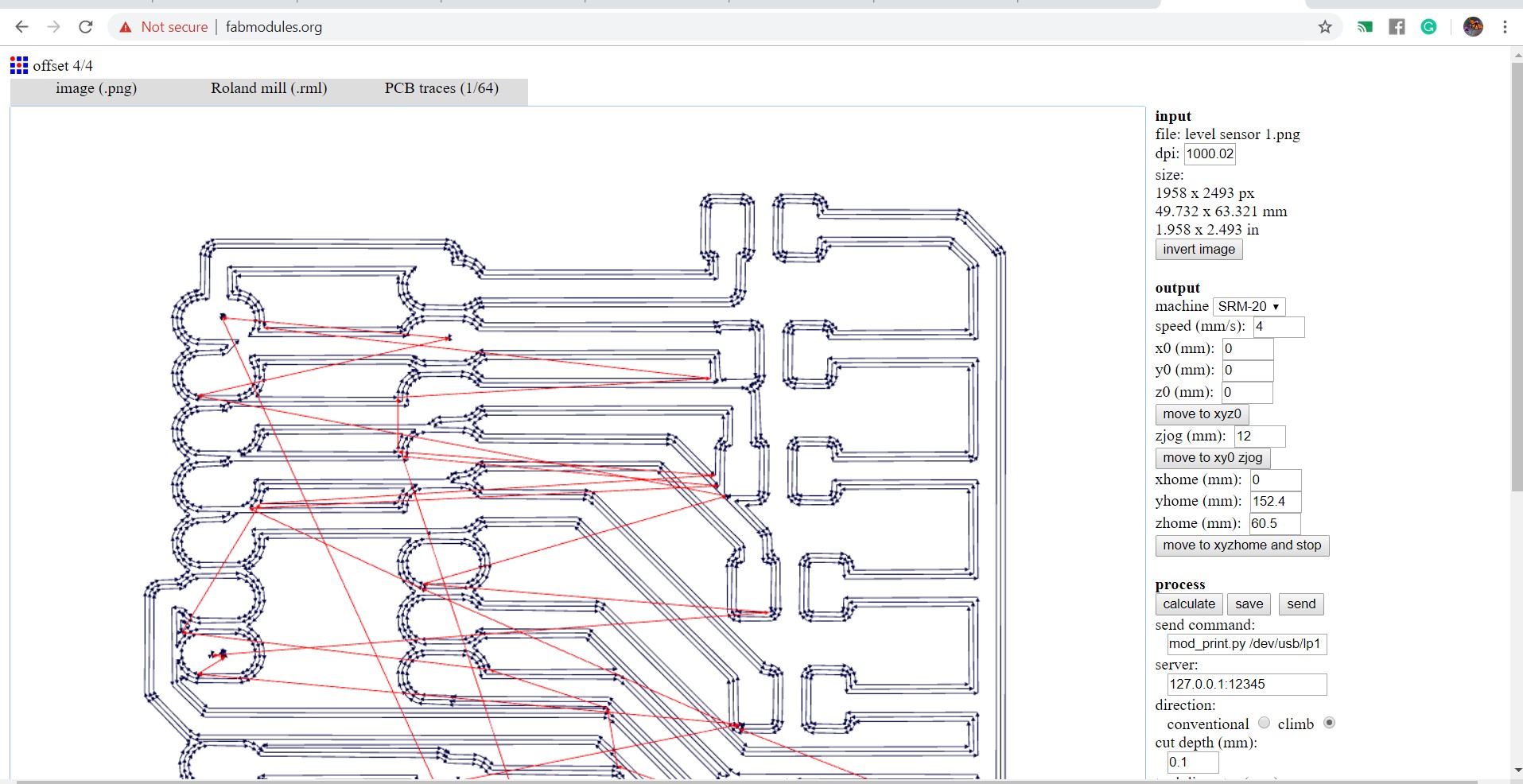
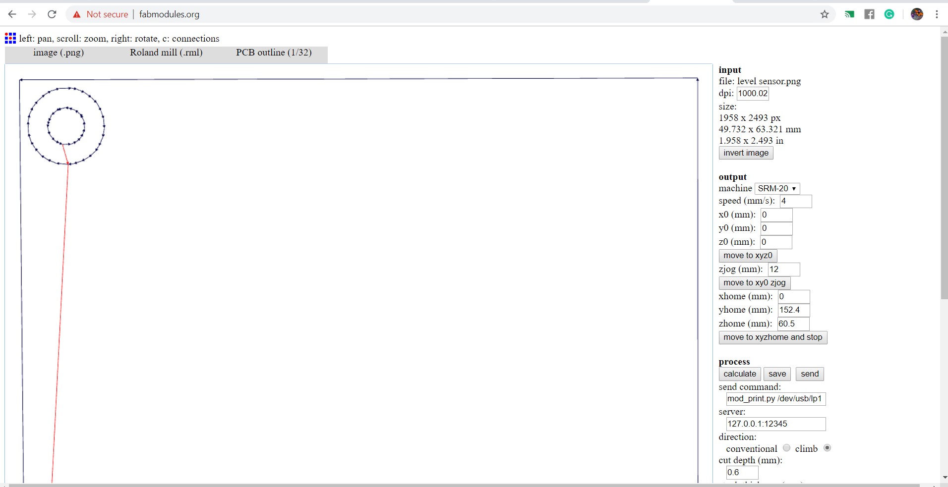
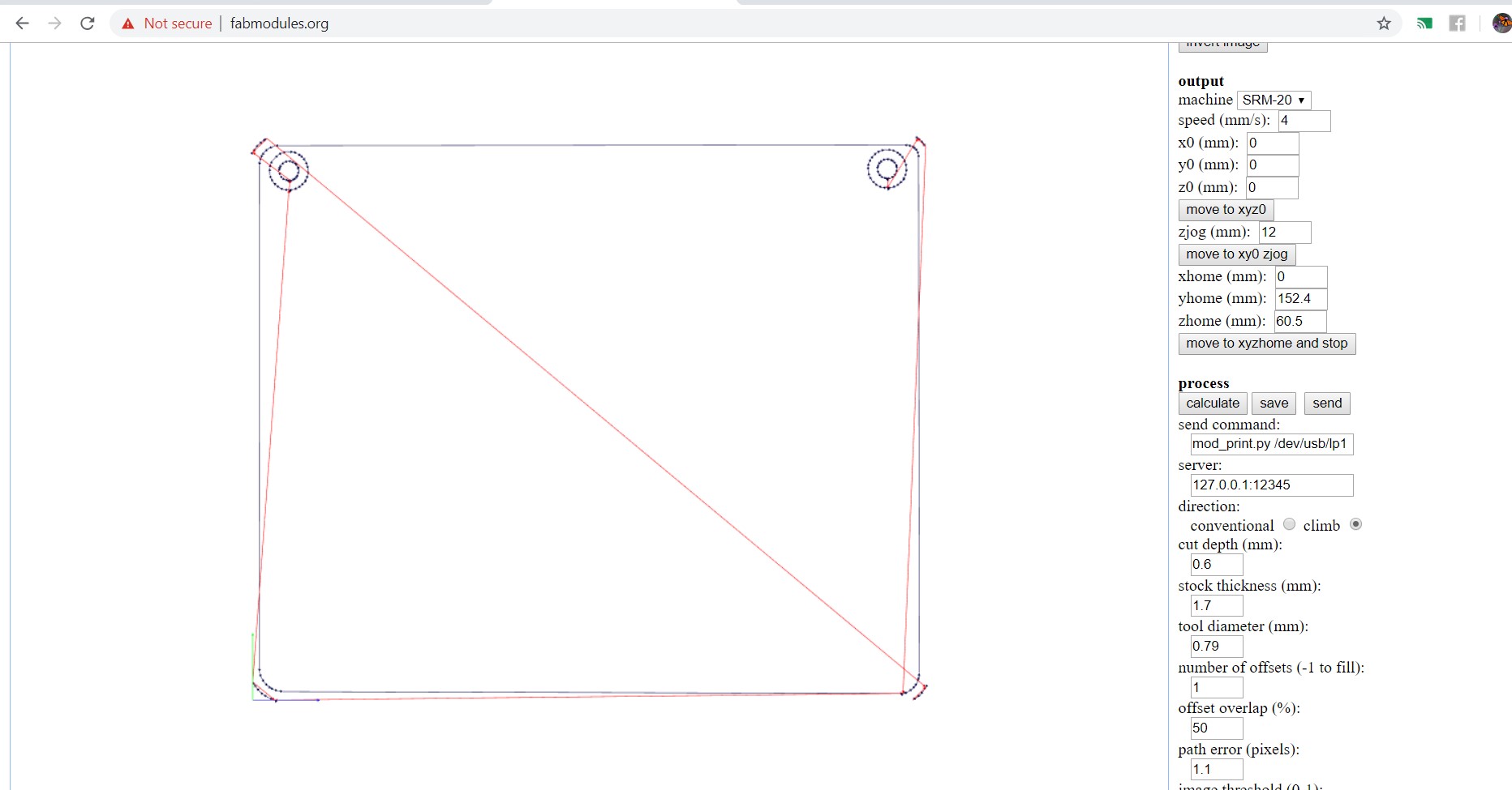
I used fabmodules for making .rml file
|
|
I learned how to design the PCB. I used Eagle for designing the PCB of the final project. For designing, used Atmega328p IC which has 32 input or output pins fixed on my final board.
Open the eagle softawre and started schematics.my output board of final project is LED Matrix Display.I used GSM Module for sending messege receiver side to transmitter side.GSM module has 3 pins(RXD,TXD and GND),So,I took 3 pin header for output.
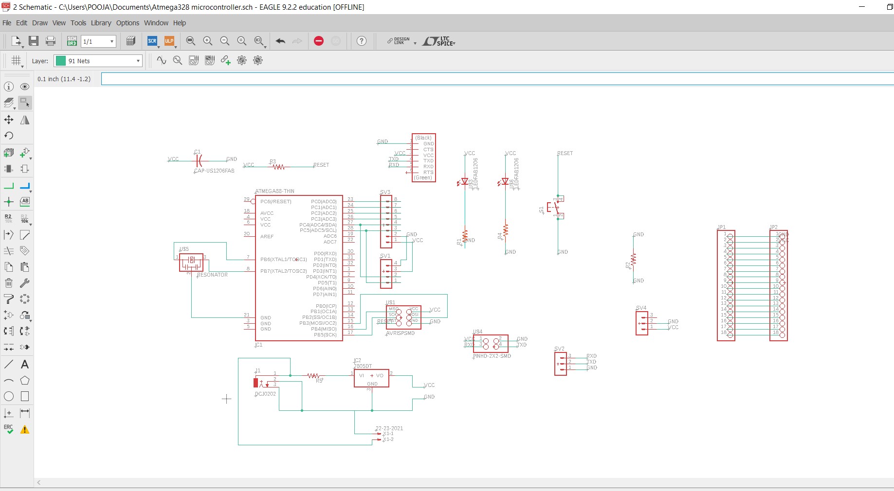
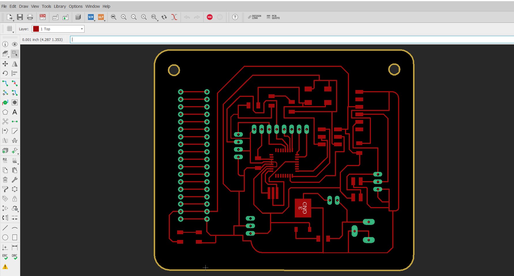
A 20Mhz resonator connected across the XTAL1 and XTAL2 pins.Join push button to reset pin and another pin of the switch is grounded.Crystal connected across the XTAL1 and XTAL2, add the load capacitances from the pins to ground. I used Resonator instead for Crystal oscillator because it already has capacitors inbuild.
I used 8 pin header for inputs from sensor.and also used 3 pin header for output(GSM Module).then I used LED for indicator,switch,power jack for supply.
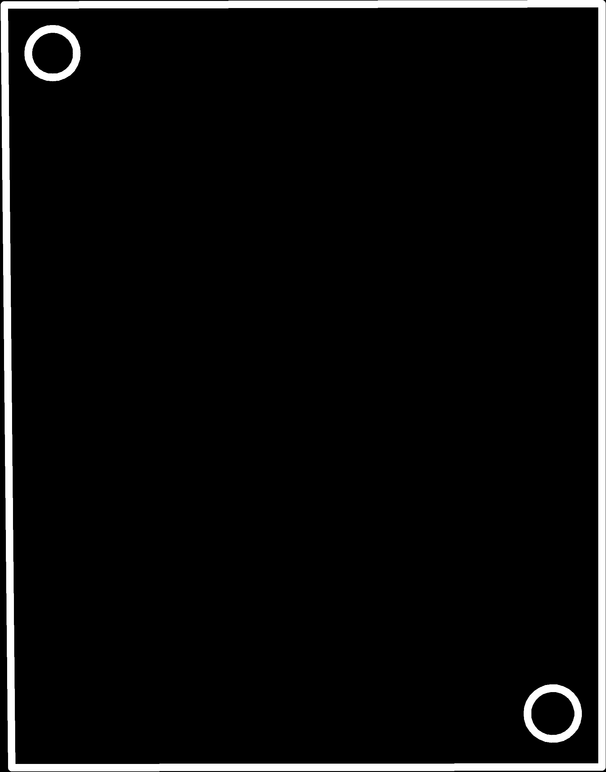
After design the pcb in eagle and export the traces, dimension and dill paths separately, save it as png ( use monochrome mode to export the images )
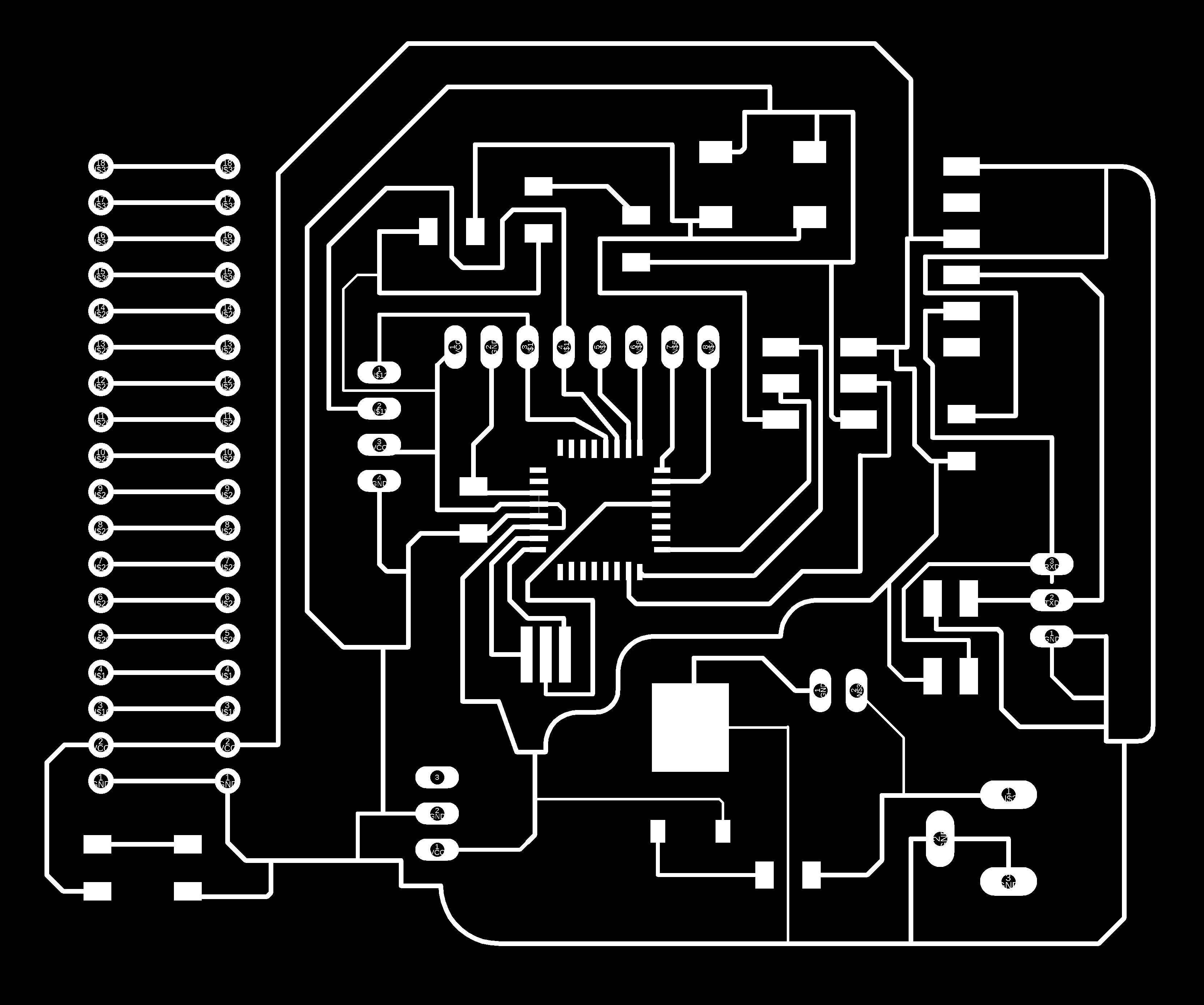
After opening the traces image in fabmodule and choose use 1/32 bit to mill the pcb.while drawing the traces I gave 0.012 inch as the trace width.
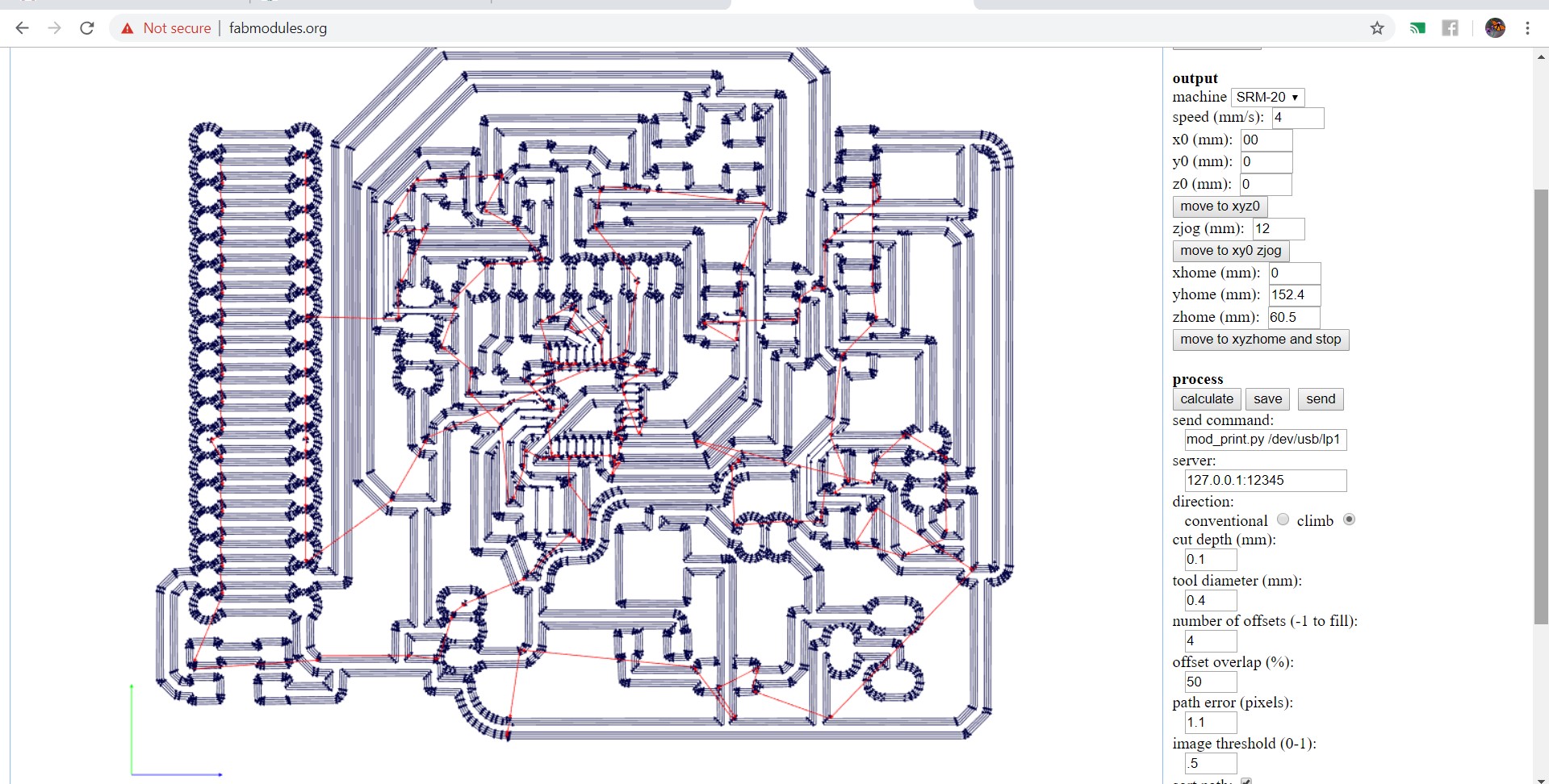
the traces image in fabmodule and choose use 1/364 bit to mill the pcb.
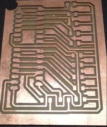
Then milling board.
I have made same board for my Output device
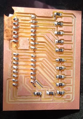
Soldering
What component I used?
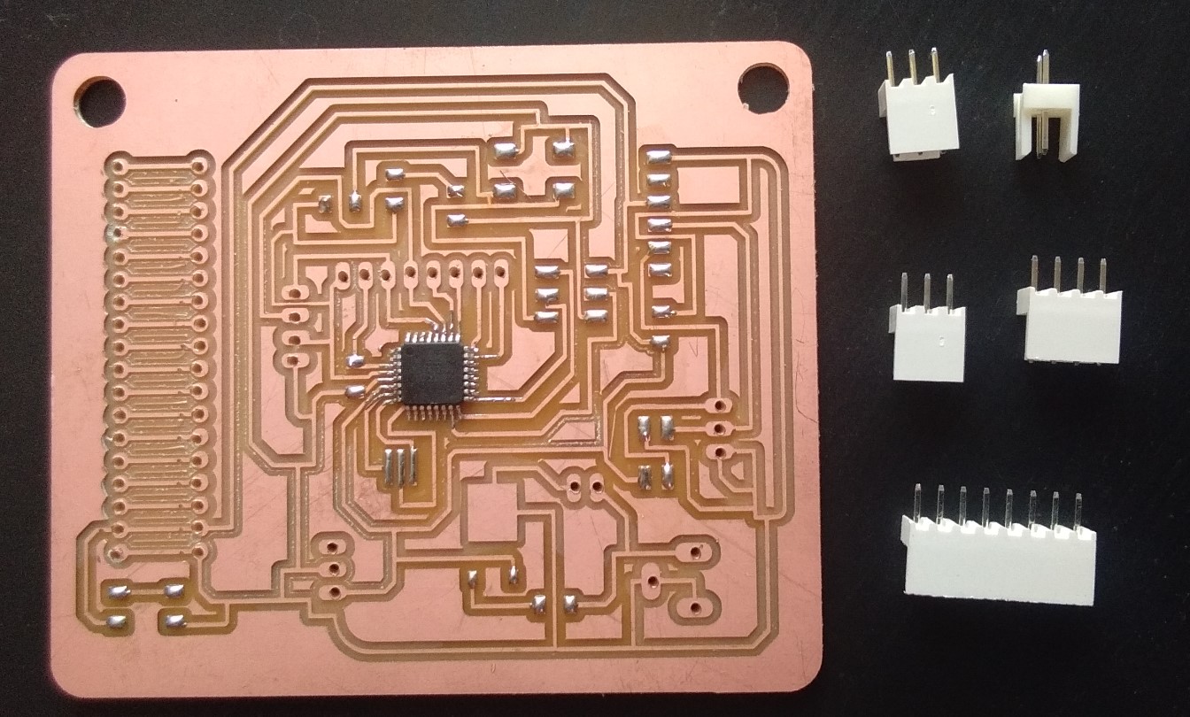
Soldering board
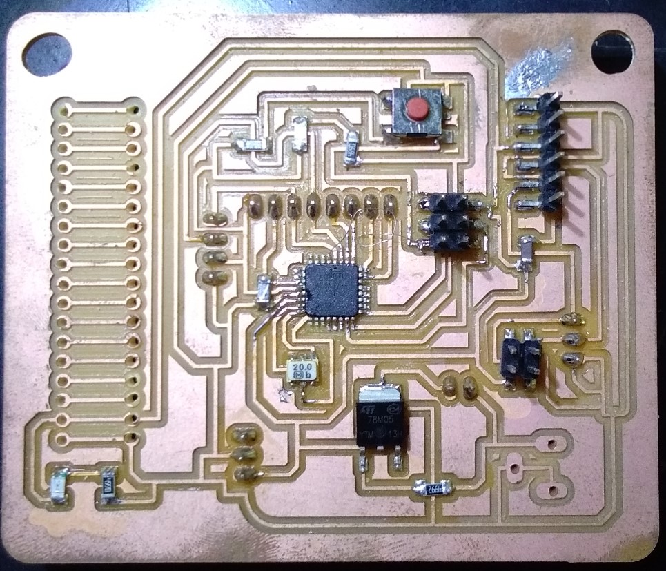
I have made a two module first is Transmitter side and second is receiver side.
I made this Assignment in this week Input Device
I made this Assignment in this week Output Device
ProgrammingHere is the code of Transmitter side.
                //Made on 10/06/2019
//Project by : Pooja Jadhav
//Transmitter code
//Dam water level controller


//GSM SIM800//
#include
SoftwareSerial mySerial(7,8); // RX, TX

void setup()
{
  Serial.begin(9600);// start serial port
  mySerial.begin(9600);
}

void loop()
{
     if (mySerial.available())
     Serial.write(mySerial.read());
     delay(10000); //Give enough time for GSM to register on Network
     SendSMS();    //Send one SMS
     //delay (60000);
     delay (60000);
   // while (1);

}

int level1 (int x)
{
   x = analogRead (A0);
 //Serial.println(x);
  return x;
}

int level2 (int y)
{
   y = analogRead (A1);
  //Serial.println(y);
  return y;
}

int level3 (int z)
{
   z = analogRead (A2);
 // Serial.println(z);
  return z;
}

int level4 (int p)
{
   p = analogRead (A3);
 // Serial.println(p);
  return p;
}

int level5 (int q)
{
   q = analogRead (A4);
 // Serial.println(q);
  return q;
}


void SendSMS()
{
  int a,b,c,d,e,f,g,h,i,j,k,l,m,n;
  a = level1(h);
  b = level2(i);
  c = level3(j);
  d = level4(k);
  e = level5(l);
 // f = level2(m);
 // g = level2(n);

  Serial.println(a);Serial.println(b);Serial.println(c);Serial.println(d);Serial.println(e);

  mySerial.println("AT+CMGF=1");    //To send SMS in Text Mode
  delay(1000);
  mySerial.println("AT+CMGS=\"+919112735153\"\r"); //Change to destination phone number
 // mySerial.println("AT+CMGS=\"+918380862704\"\r");
  delay(1000);
  //mySerial.println ("Water Level 100%");

   if (a > 100 && b > 100 && c > 100 && d > 100 && e > 100 )
 {
    mySerial.println ("Water Level 100%");
    Serial.println ("Water Level 100%");
   delay(1000);
 }


 else if (a > 100 && b > 100 && c > 100 && d > 100 )
 {
    mySerial.println ("Water Level 75%");
    Serial.println ("Water Level 75%");
     delay(1000);
 }


 else if (a > 100 && b > 100 && c > 100 )
 {
    mySerial.println ("Water Level 50%");
    Serial.println ("Water Level 50%");
     delay(1000);
 }

 else if (a > 100 && b > 100 )
 {
    mySerial.println ("Water Level 25%");
    Serial.println ("Water Level 25%");
    delay(1000);
 }

  else if (a > 100 && b <= 100)
 {
    mySerial.println ("Water Level  5%");
    Serial.println ("Water Level  5%");
    delay(1000);
 }

 else if (a < 100 && b < 100 && c < 100 && d < 100 && e < 100 )
 {
    mySerial.println ("Water Level  0%");
    Serial.println ("Water Level  0%");
    delay(1000);
 }

   mySerial.println((char)26); //the stopping character Ctrl+Z
  delay(500);


}
Trial..
design
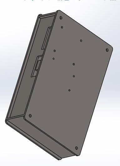
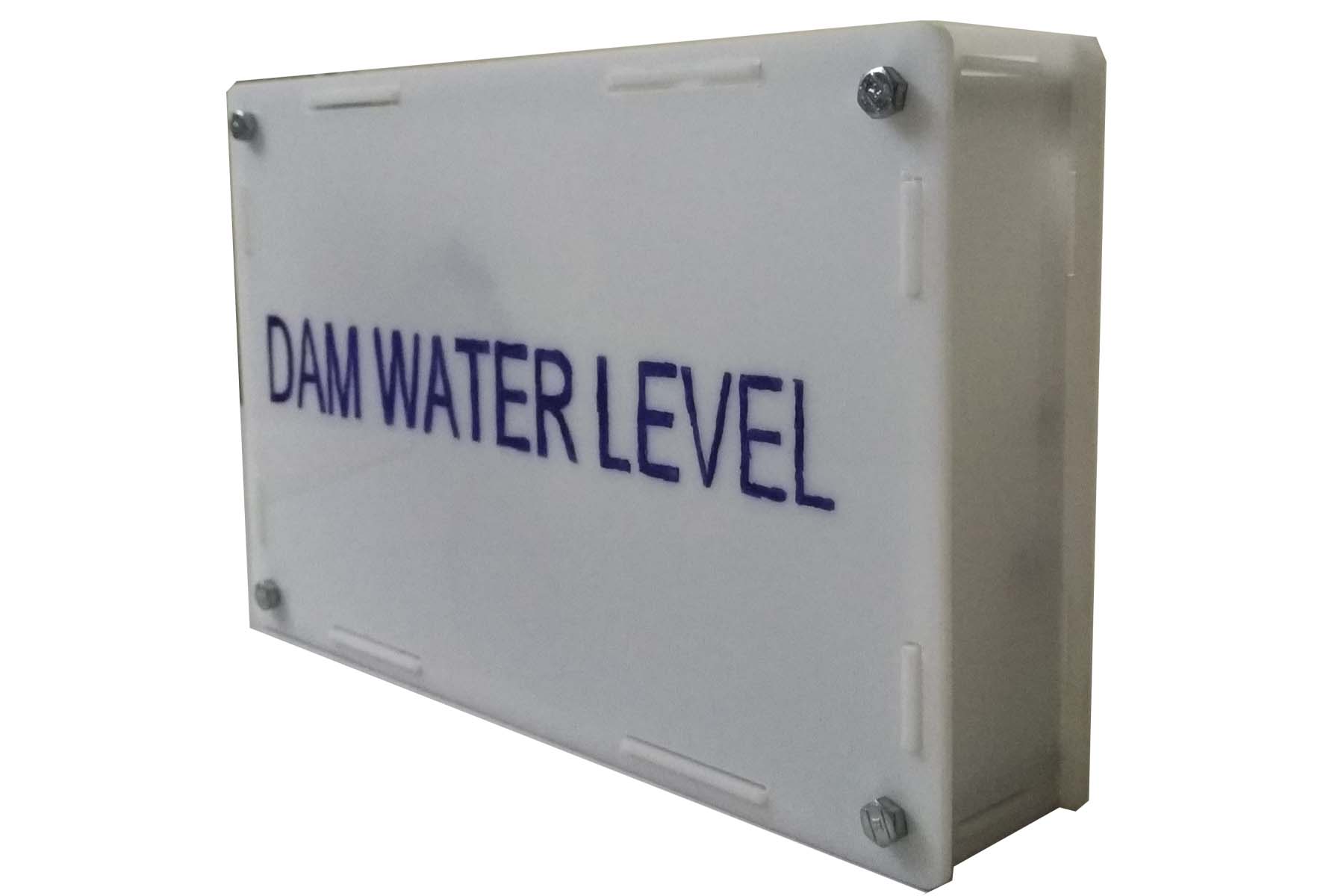
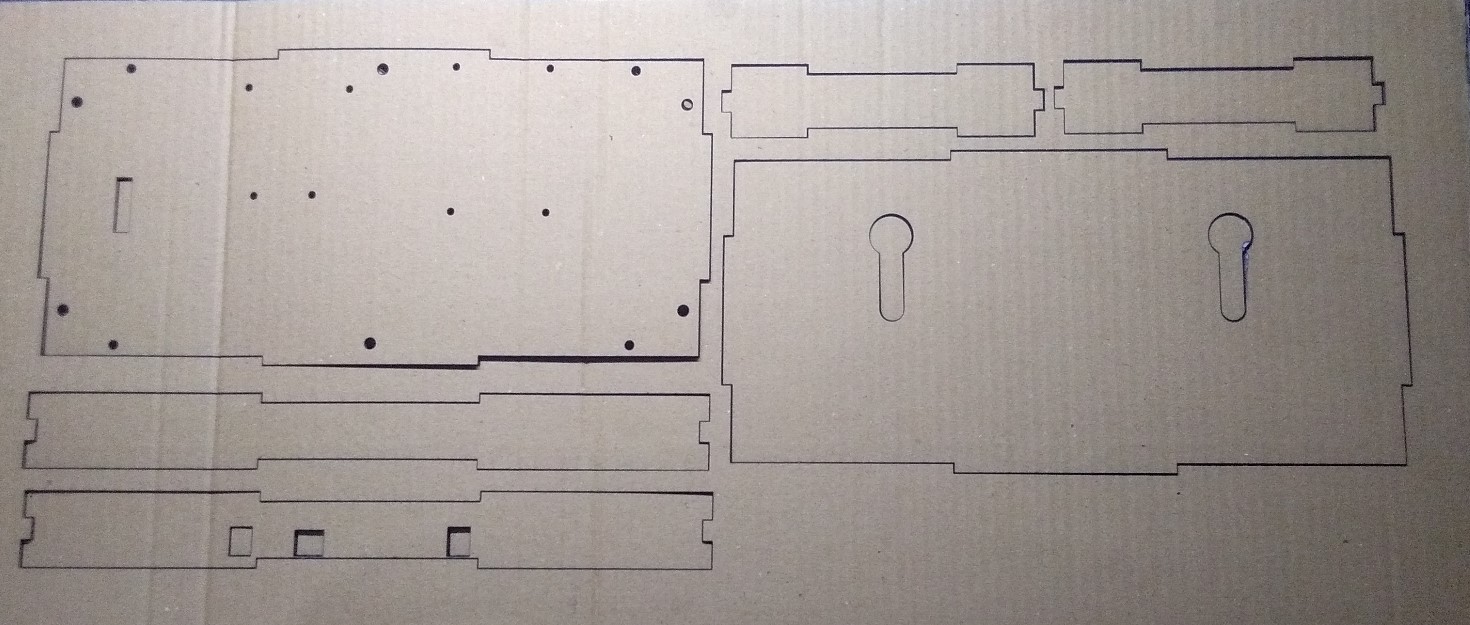
Casing
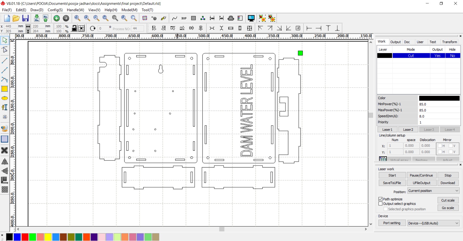
We have to do laser cutting assignments. I cut all project related parts in SIL LASER.
After Design I took a trial on Carboard.It pressfit perfectly. Then I was cutting on White Acrylic sheet
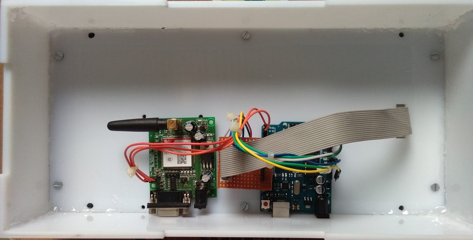
AssemblyThen I did Assemble this part.O Dam there is no electricity that why I using battery for power supply.
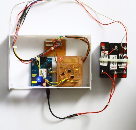
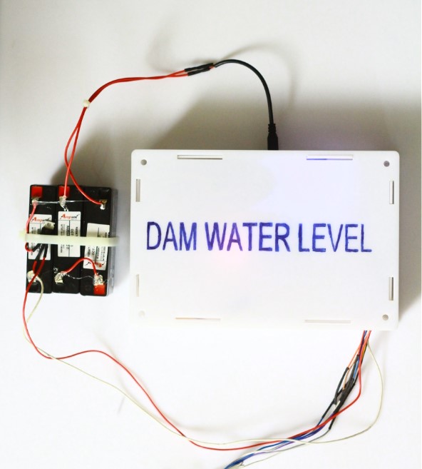
Transmitter side
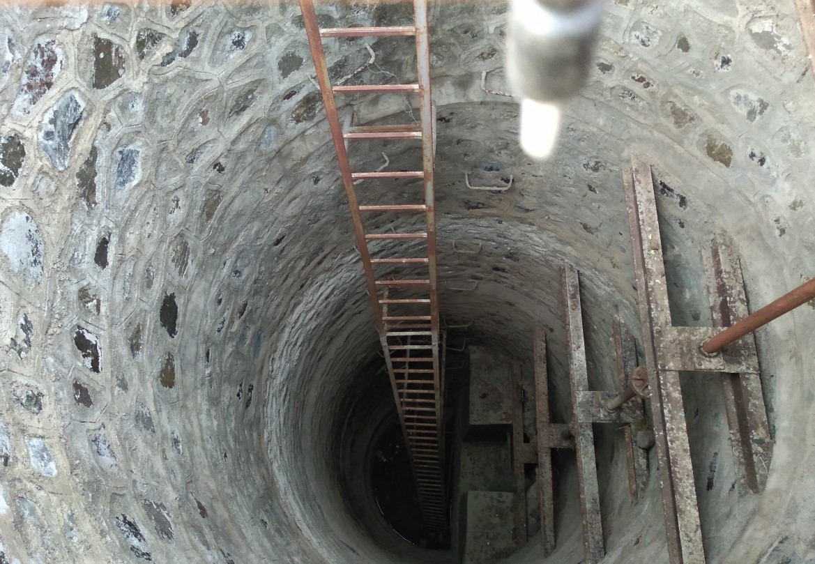
InstallationEvery Dam have the one Well.With the refernce of this well I am measuring Water level.Dam and well is similar base level.
How I FittedWell height is 15m.I took pipe of similar height of well and fitted the sensor in different measurement.
here is the well
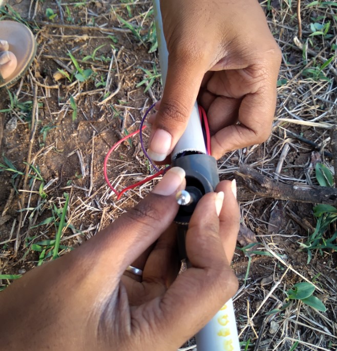
I attached the level sensor of pipes

For holding the sensor I used T-slot use in pipe.
Receiver side
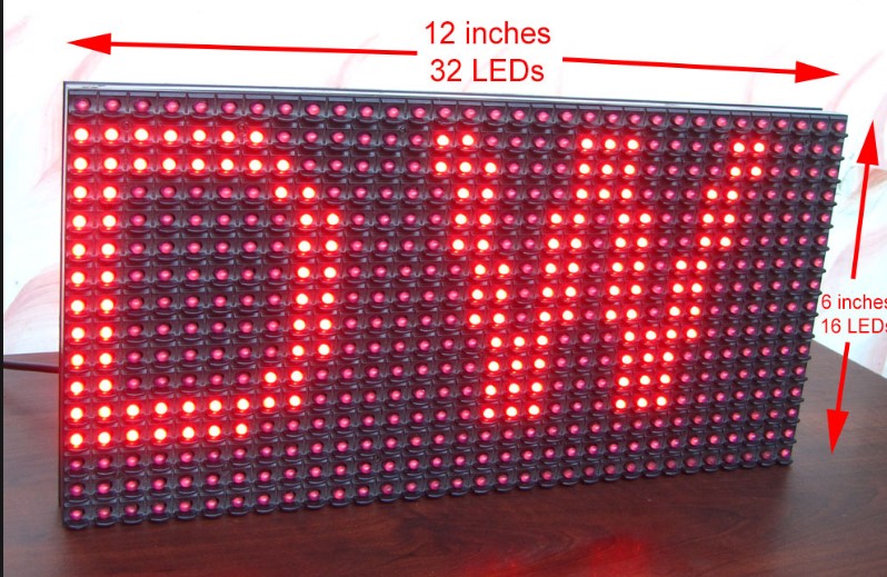
LED Matrixlittle bit of Times Square into your home with our RGB LED matrix panels. These panels are normally used to make video walls — here in New York we see them on the sides of buses and on bus stops — to display animations or short video clips. We thought they looked really cool so we picked up a few boxes from the factory.
These panels require 12 or 13 digital pins (6 bit data, 6 or 7 bit control) and a good 5V power supply, at least a couple amps per panel.
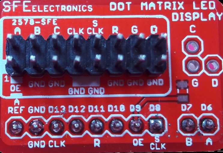
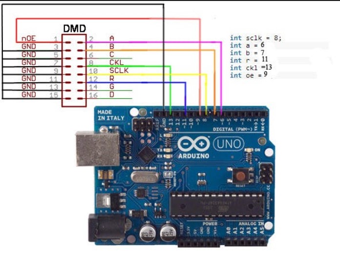
DMD Connector
This handy Dot Matrix Display Connector allows you to plug an LED panel with a HUB12 interface straight in to an Arduino-compatible board.
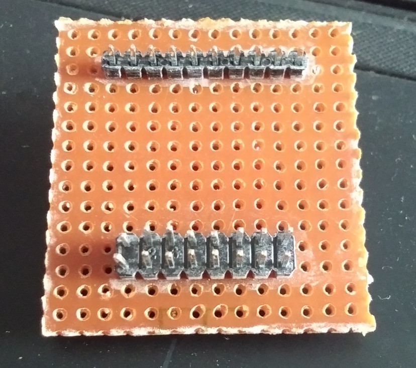
I made DIY DMD Connector.following this image.
I made this connector on general purpose PCB.
Features
DMD connector used for the connect the led matrix to board.LED matrix have 8 pin connector for input and output.DMD connector also have 8pin connector.Led matrix connect to dmd connector and dmd connector go to board.
Here is receiver side
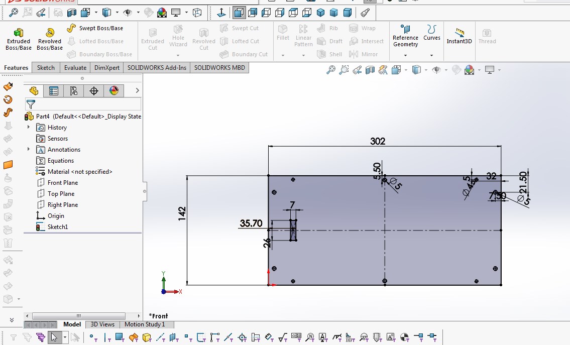
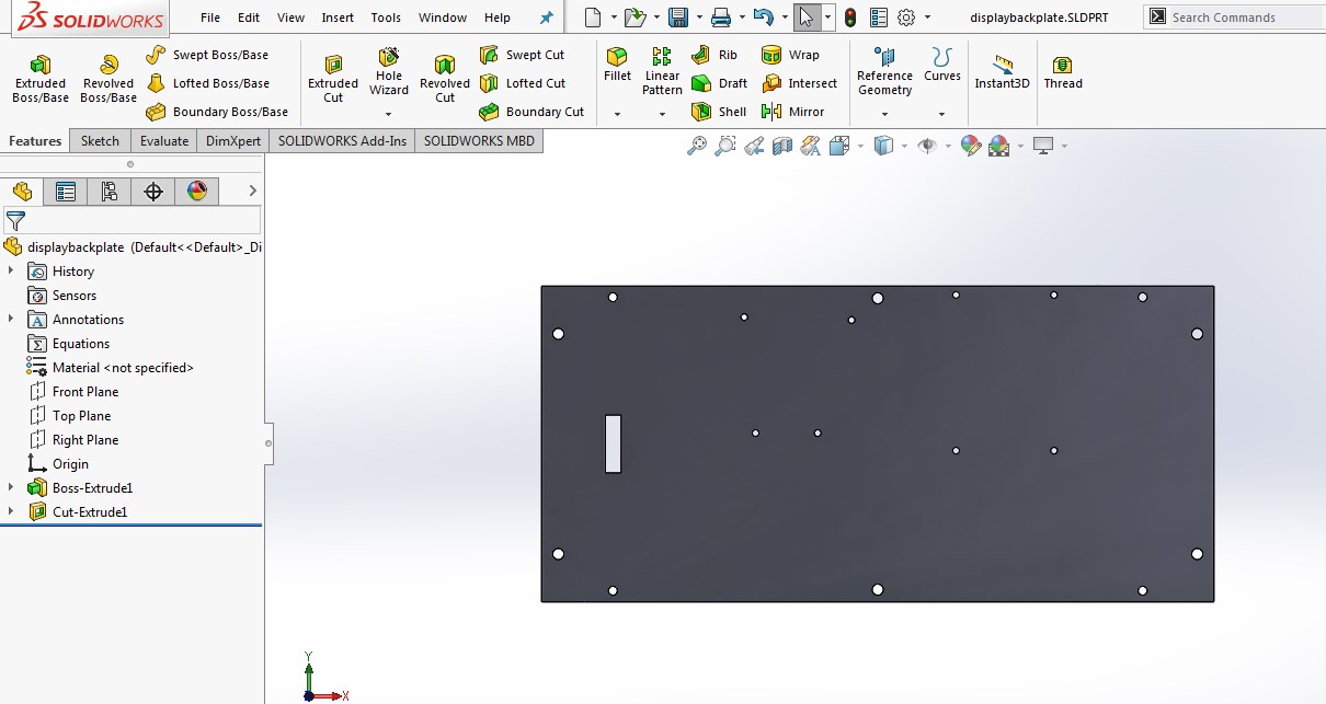
I design box casing in solidwork.I drew 6 side plate.
This is the T-slot for holding this LED on Wall.
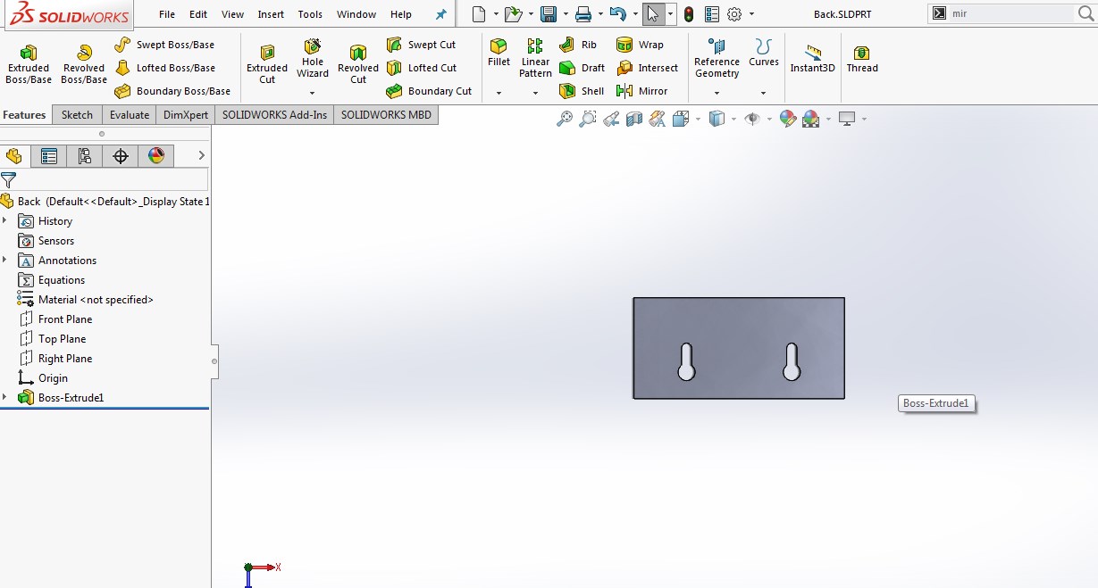
This plate for the surface mounting
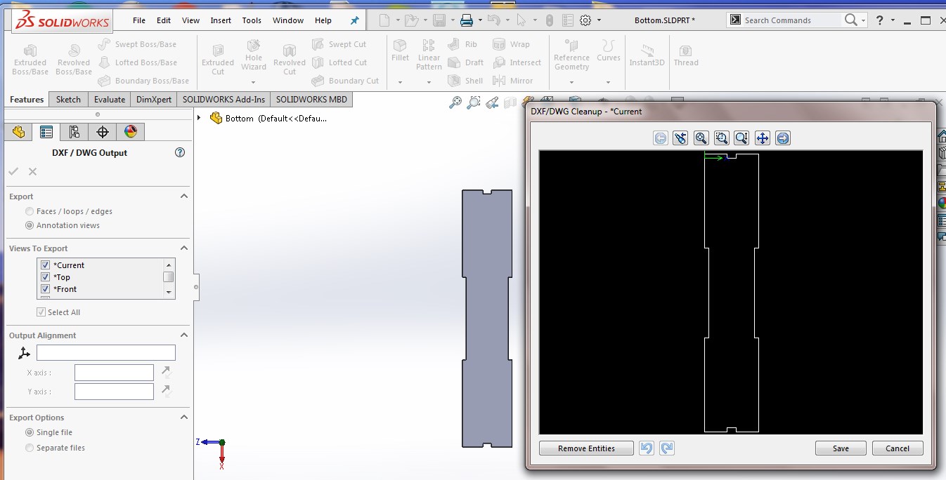
made a dxf file
I made project transmitter part only. And for receiver part I used Arduino Board.
I designed in this week Computer controlled cutting
Here is the code of Receiver side.
                     #include

SoftwareSerial mySerial(A5, A4); // RX, TX

#include
#include
#include
#include

bool led = false;
// Set Width to the number of displays wide you have
const int WIDTH = 1;

// You can change to a smaller font (two lines) by commenting this line,
// and uncommenting the line after it:
const uint8_t *FONT = Arial14;
//const uint8_t *FONT = SystemFont5x7;

//const char *MESSAGE = "abcdefghijklmnopqrstuvwxyz";

SoftDMD dmd(WIDTH, 1); // DMD controls the entire display
DMD_TextBox box(dmd);  // "box" provides a text box to automatically write to/scroll the display

char quote = 0x22;


bool GSM_operational(void);

String sms = "";
String Caller_id;
String Text;

char character;
int indexOfQuotes[10];

double time_start;
double time_current;

bool recieve_mode = false;
bool msg_recieve = false;
bool print_msg = false;
bool time_registered = false;
bool msg_fetched = false;
bool start_recieve = false;
//------------------------------------------------------------------------------------------------------------------------
void setup()
{

  dmd.setBrightness(255);
  dmd.selectFont(FONT);
  Serial.begin(9600);
  Serial.println("GSM started");
  if (mySerial.available())
  {
    Serial.print("OOOOkAAAy \n");
  }
  mySerial.begin(9600);
  mySerial.setTimeout(2000);
  Serial.setTimeout(2000);

}

//------------------------------------------------------------------------------------------------------------------------

void loop()
{
  // Start operating in recieving mode

  while (!recieve_mode)
  {
    mySerial.print("ATE0");// Echo mode 0/off
    delay(500);

    if (GSM_operational())
      mySerial.print("AT");
    delay(500);

    if (GSM_operational())
      mySerial.print("AT+CMGF=1"); //select sms message format 1/text mode
    delay(500);

    if (GSM_operational())
    {
      mySerial.print("AT+CNMI=2,2,0,0,0\r" );//new sms message indicator
      delay(500);
      recieve_mode = true;

      delay(500);
      while (mySerial.available())
      {
        char response = mySerial.read();
        Serial.println(response);
      }

      Serial.println("Recieve mode On");
      msg_fetched = true; //turn it on off

    }
  }
//  if (led == true) {
//    dmd.begin();
//    char nxt[5];
//    Text.toCharArray(nxt, 5);
 //   for (int x = 0; x < 5 ; x++)
//    {
//      box.print(nxt[x]);
//    }
//    led = false;
//  }


  if (recieve_mode)                                    // Wait for msgs to recieve
  {
    Serial.print("receive clear \n");


    {
      while (mySerial.available())
      {
        Serial.print("gygygv \n");
        if (!time_registered)           //Capture the time of start of message recieving
        {
          time_start = millis();
          time_registered = true; //turn it on later
        }
        char character = mySerial.read();
        sms.concat(character);
      }

    }
  }
  Serial.print("receive complete \n");
  if (msg_fetched)
  {
    Serial.println("Msg Recieved");
    print_msg = true;
    msg_fetched = false;
  }


  while (print_msg)                                         // As message is recieved, time to get the caller id and text
  {

    extract_msg();

    Serial.println("SMS from : ");
    Serial.println(Caller_id);
    Serial.println("Text: ");
    Serial.println(Text);

    led = true;
    print_msg = false;                           // Task complete, Turn of all Flag
    time_registered = false;
    msg_fetched = true;
    //recieve_mode = false;*/
    sms = "";
  }//Clear string
}

//------------------------------------------------------------------------------------------------------------------------
double operational_time;

bool halt_fetch (void)
{
  bool halt = false;

  if (time_registered)
  {
    time_current = millis();
    operational_time = time_current - time_start - 100;
  }

  if (operational_time > 5000 || sms.length() == 500 )  {                 // Halt condition
    halt = true;
    operational_time = 0;
  }

  return halt;
}
//------------------------------------------------------------------------------------------------------------------------
void extract_msg (void)
{
  int Length, i, index = 0;

  Length = sms.length();
  for (i = 0; i <= Length; i++)
  {
    if (sms.charAt(i) == quote)
    {
      indexOfQuotes[index] = i;
      index++;


    }

  }
  indexOfQuotes[index] = '\0';

  Caller_id = sms.substring(indexOfQuotes[0] + 1, indexOfQuotes[1]);
  Text = sms.substring(indexOfQuotes[5] + 3);

}
//----------------------------------------------------------------------------------------------------------------------

bool GSM_operational(void)
{
  int count = 0;
  bool Status = false;
  mySerial.println();
  while (1)
  {
    if (mySerial.available() > 0)
    {
      char data = mySerial.read();
      if ( data == 'O' || data == 'K')
      {
        Serial.println("OK1");
        Status = true;
        break;
      }
      if ( data == 'E' || data == 'R' || data == 'O')
      {
        Serial.println("GSM not functional");
        Status = false;
        break;
      }
    }
    count++;
    delay(10);
    if (count == 100)
    {
      Serial.println("GSM not connected");
      Status = false;
      break;
    }
  }
  return Status;
}
Result
Here is the Presentation slide
Here is the Presentation video
Download all the files are related to project
You can Download .rml file
You can Download PNG file
You can Download Transmitter dxf file
You can Download receiver dxf file
You can Download Project Code
You can Download Original file
Project License
For License I choose Creative Commons(CC).For more Information HERE

Fab lab by Pooja Jadhav is licensed under a Creative Commons Attribution-ShareAlike 4.0 International License.
Based on a work at http://fabacademy.org/.
Permissions beyond the scope of this license may be available at http://vigyanashram.com/.