Weekly Task
Group assignment
Use the test equipment in your lab to observe the operation of a microcontroller circuit board
Individual assignment
- Redraw the echo hello-world board
- add (at least) a button and LED (with current limiting resistor)
- check the design rules, make it, test it, simulate its working and render it
This is electronic design week in which we have to learn the circuit designing software and redraw the hello board and add a LED and a button. It sounds simple, but I knew it will going take lots of study to understand where to put them.
What is Eagle
EAGLE (Easily Applicable Graphical Layout Editor) is a flexible and expandable EDA schematic capture, PCB layout, autorouter and CAM program. EAGLE is popular among hobbyists because of its freeware license and rich availability of component libraries on the web.

Neil provided several images for the hello board.png. then I downloaded Eagle software and installed it on my windows OS.The procedure is very simple and one can dowwnload the free software from the official Autodesk website.
In this software 2 main steps in designing a PCB in Eagle.
1.Schematic section- In this section we can add components our PCB and specify the connection between them. we can also add the values of componenets.2.Board section - In this section we will decide the route of connections of various components of the PCB.
Basic Electronic
1.Capacitor-C: A capacitor is a passive electronic component that stores energy in the form of an electrostatic field.
Resistor: A resistor is an electrical component that limits or regulates the flow of electrical current an electronic circuit. Resistors can also be used to provide a specific voltage for an active device such as a transistor.
Current- I: Current is a flow of electrical charge, usually electrons or electron-deficient atoms.
Volt/Voltage-V: A quantitative expression of the potential difference in charge between two points in an electrical field, for example a battery. The greater the voltage, the greater the flow of electrical current.
Ground-GND A ground is a direct electrical connection to the earth, a connection to a particular point in an electrical or electronic circuit.
Positive-VCC VCC stands for "voltage at the common collector." The letter "V" on a circuit stands for the supply voltage. The letters "CC" indicate that the supply voltage is positive or negative. If the charge is positive, its circuit is a Negative-Positive-Negative circuit, and if negative, it is a Positive-Negative-Positive circuit.
Diode: HA diode is a specialized electronic component with two electrodes called the anode and the cathode. The fundamental property of a diode is its tendency to conduct electric current in only one direction.
LED: A light-emitting diode (LED) is a semi-conductor device that emits visible light when an electric current passes through it. The light is not particularly bright, but in most LED's it is monochromatic, occurring at a single wavelength.
Battery: Batteries are a collection of one or more cells whose chemical reactions create a flow of electrons in a circuit. All batteries are made up of three basic components: an anode (the ‘-’ side), a cathode (the ‘+’ side), and some kind of electrolyte (a substance that chemically reacts with the anode and cathode).
A useful thing to remember which will come in handy when having to calculate the components, to be put on a circuit, is the following equation: R=V/I or I= V/R or V=R*I
After Completing my basic electronic lesson, I started to learn about how to design electronic circuit by eagle,(a cad design software). I learned eagle basic watching a tutorial in Youtube. Here click for tutorial.. Before starting my schematic design I follow some previous student assignment how they done their design. Then i fix up my board design how is made.
Egale VS KiCAD
Eagle- I read on CircuitDigest that time I understood Eagle has two editors; Schematic editor and PCB layout editor. The schematic editor is used to add all components and connect according to the circuit requirement. This schematic file has unique features like modular design block, multi-sheet schematic, electronic rule checking and real-time design synchronization. After this, schematic is directly converted into PCB layout editor, in which we can set components according to less complexity. This PCB layout editor also has some good features like alignment tools, obstacle avoidance, routing engine.These features are available in free version.
KiCad - KiCAD also have their own library, which contains most of all electrical components. This software is also available in 19 different languages and it can run in windows, Linux and MAC.KiCAD is divided into five parts; KiCAD that is project manager; Eeschema that is the schematic capture editor; pcbnew that shows layout of PCB in both 2D and 3D; gerbfile is used to generate Gerber file; bitmap2component can convert images to footprint.
Our instructor Mrs.Supriya kadam was took a session on Eagle.For more learning I followed the Eagle Tutorials given on Fab Academy website and joined the extra components as shown.
Here in Vigyan Ashram people mostly use Eagle, my instructor Miss.Komal too suggested me to use Eagle for making PCB.
PCB Design-Hello Board
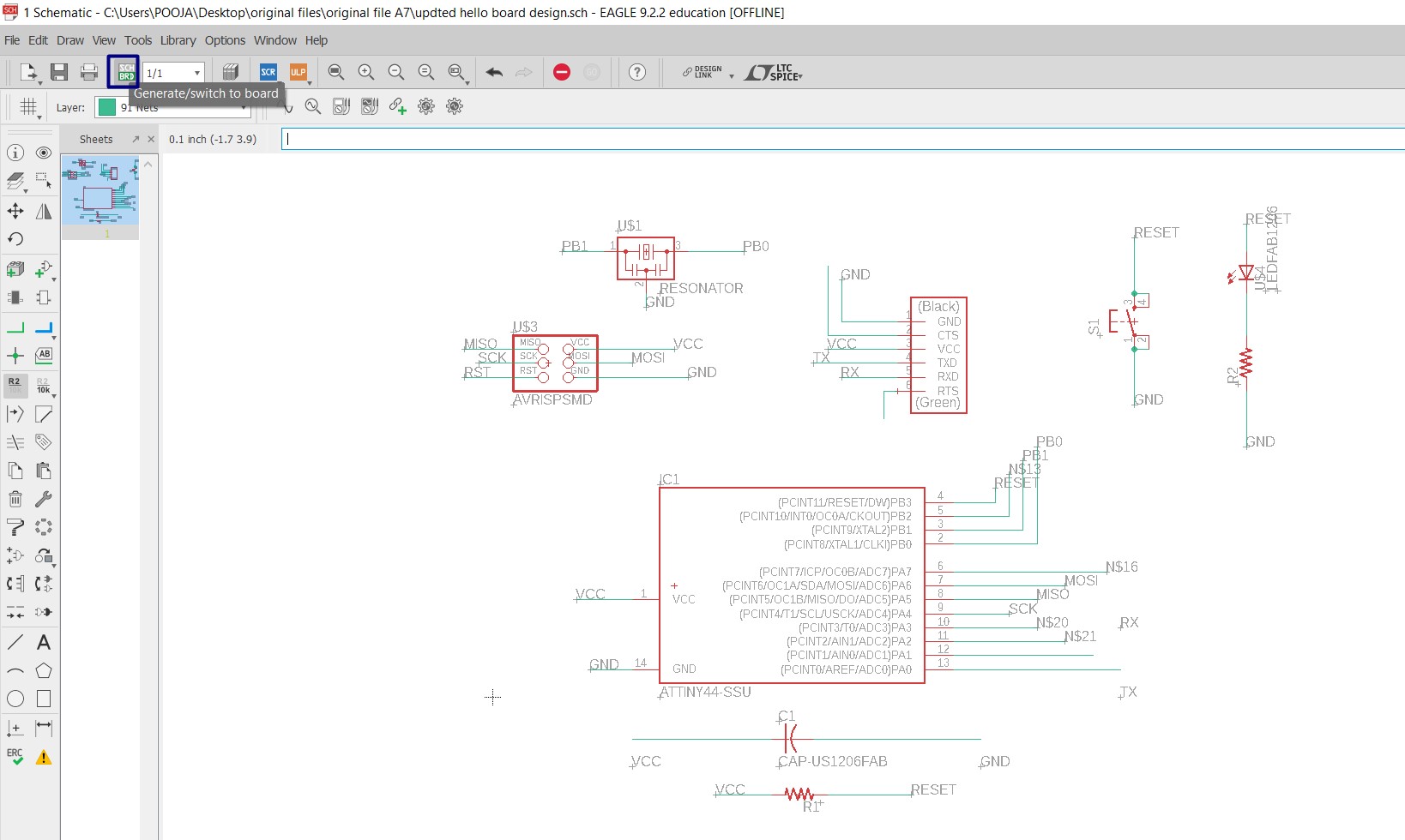
1.I opened Eagle.clicked on New and selected Schematic.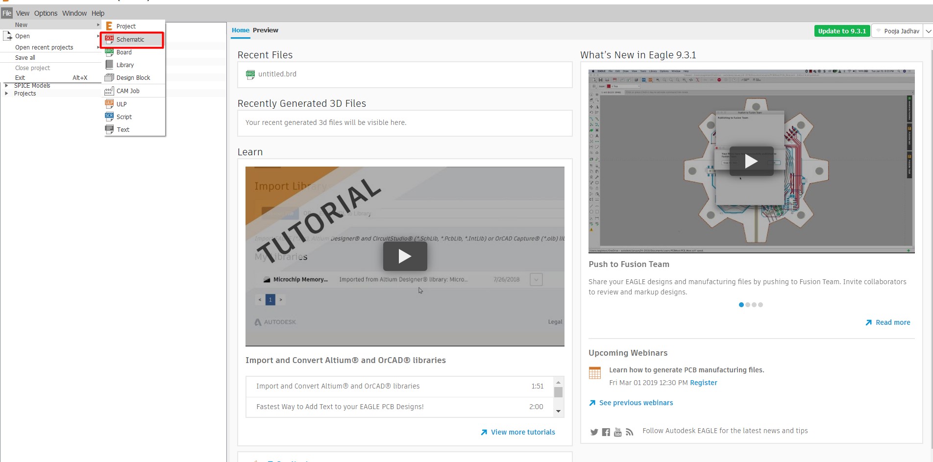
Download the Fab labs Component Library. and add it into your Eagle components library.
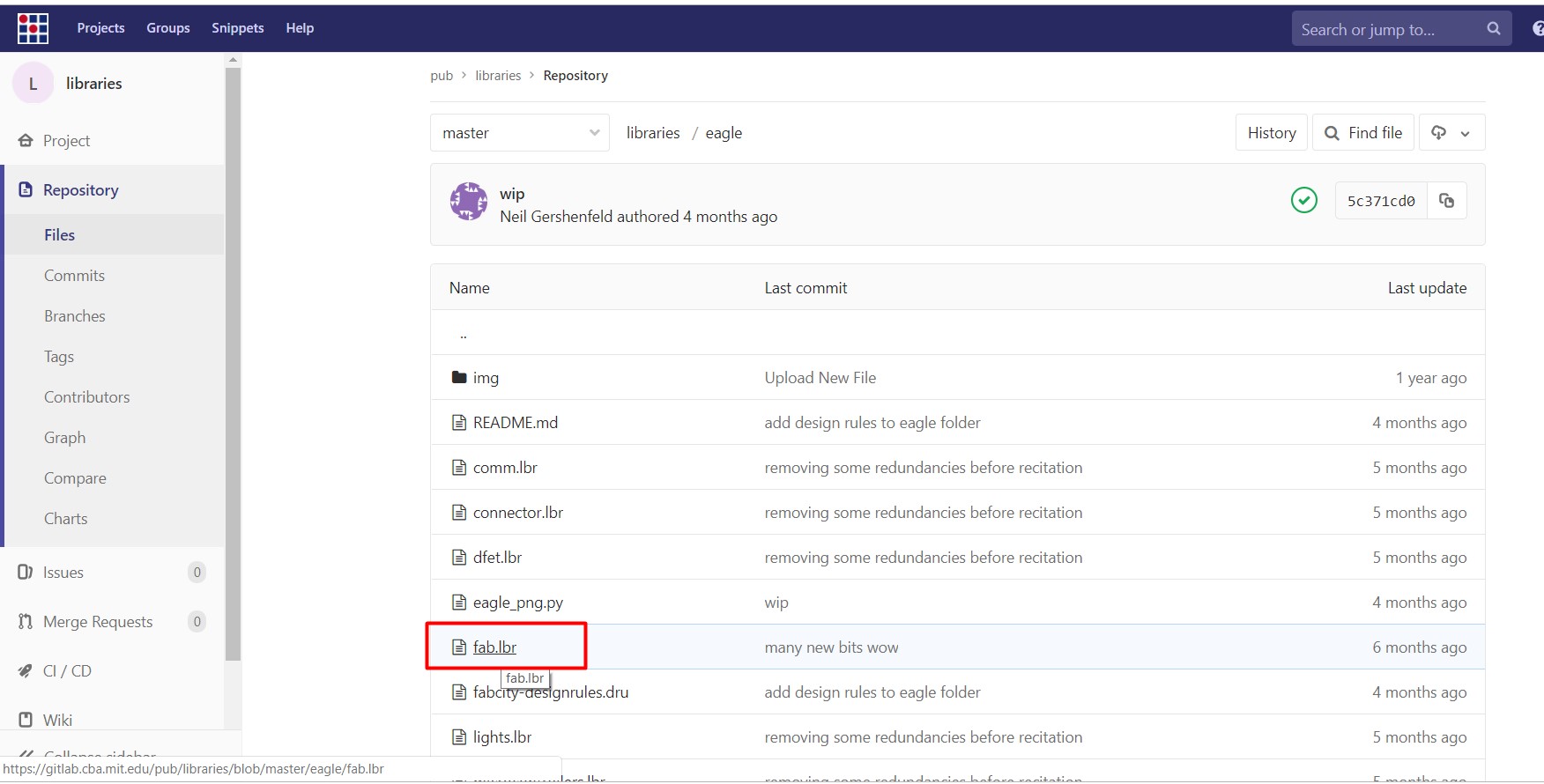
For this type "use" in command line of schematic section and search the folder in which you download the fab library and open it; than type "add" and find the fab library.
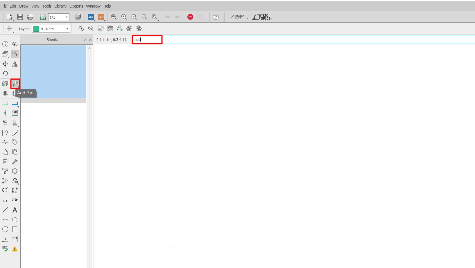
After "add" command.Click on open library Manager it will open a New window named library Manager. Go to available, select browse and add library.
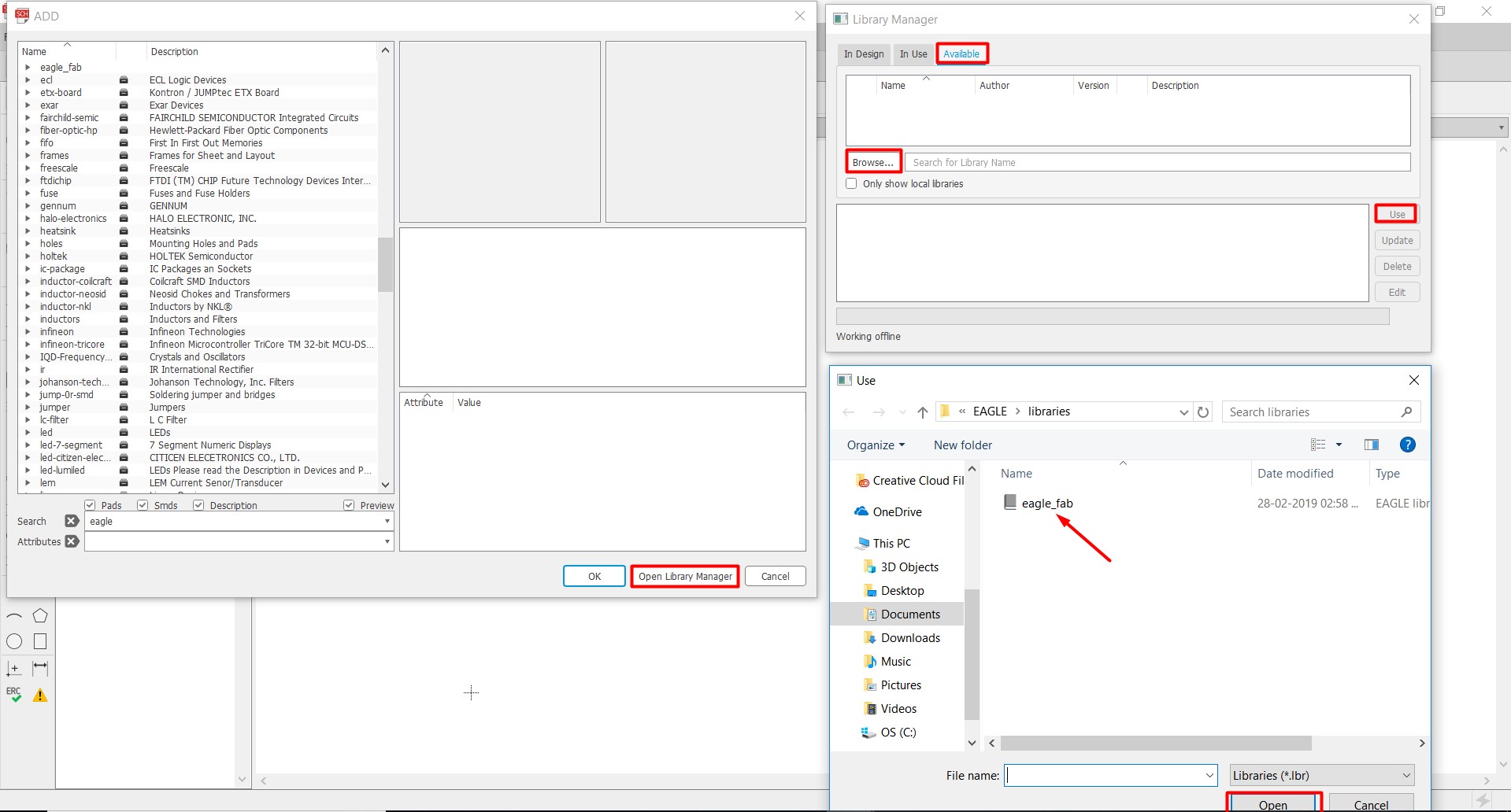
To ensure that the library has been added, type add in the command
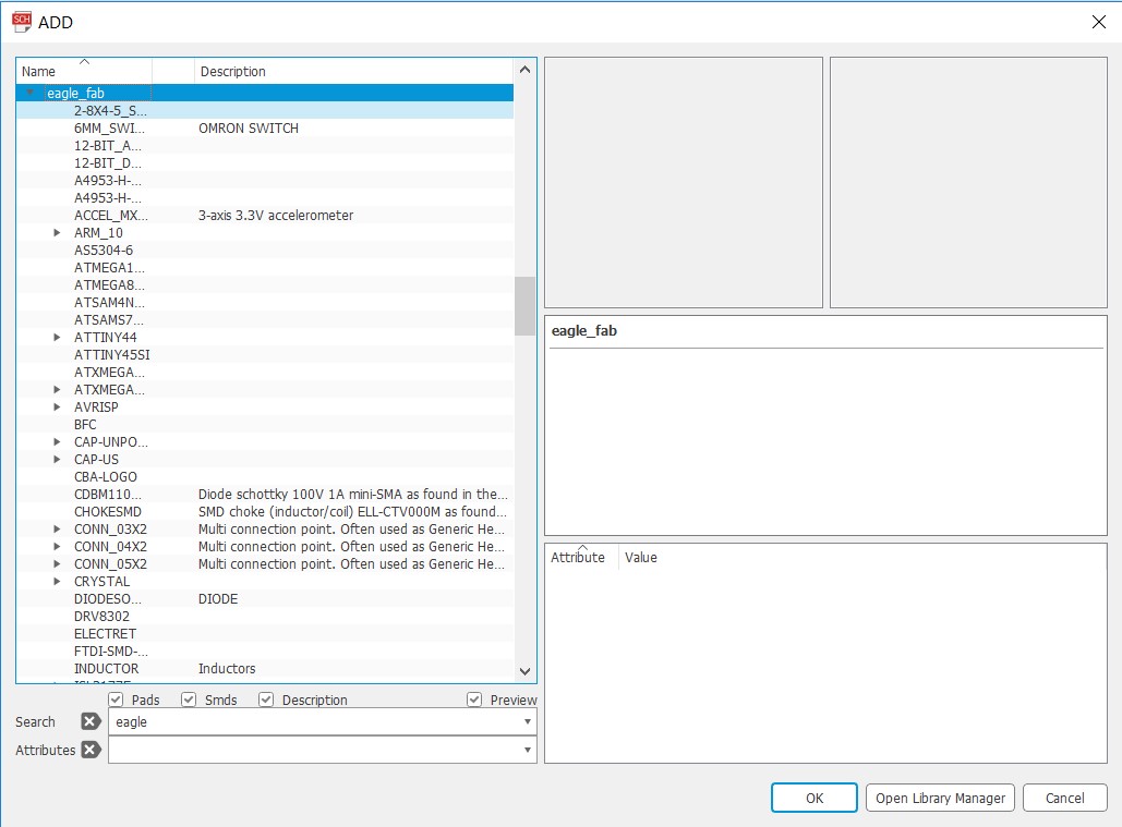
line and find the fab library.
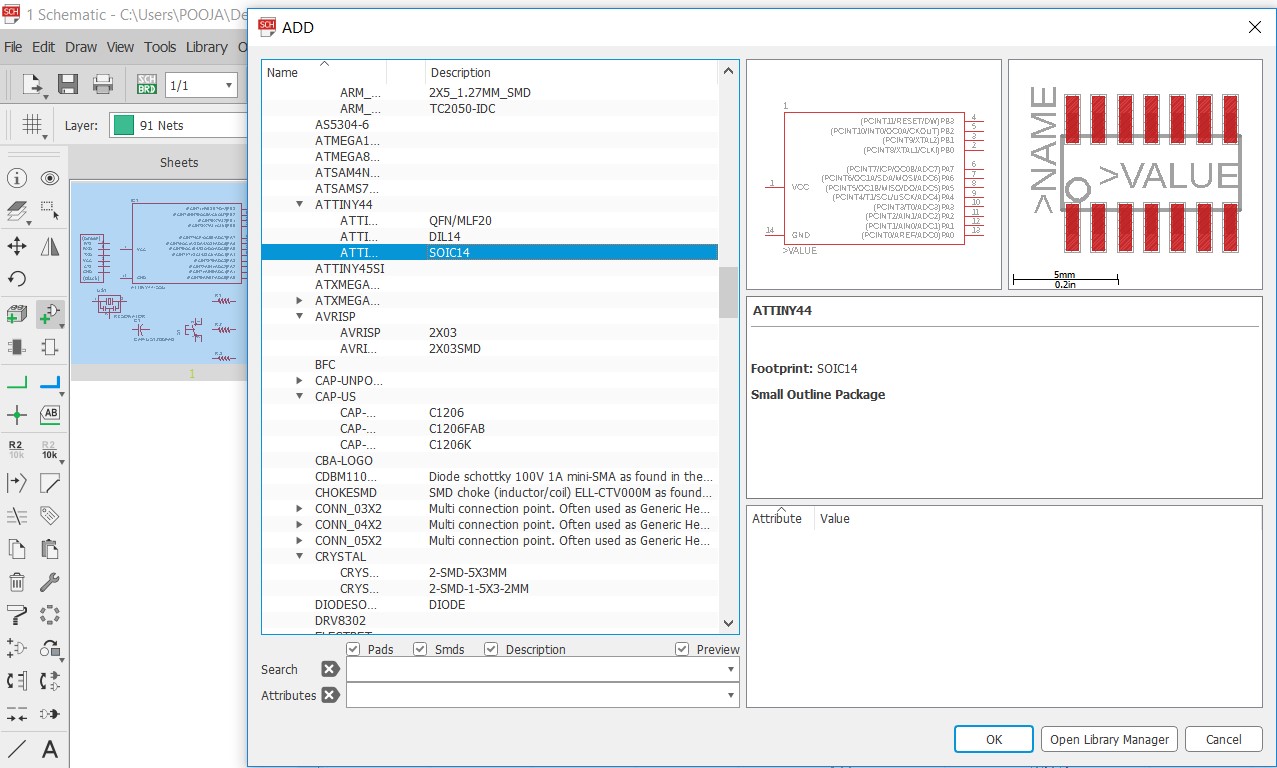
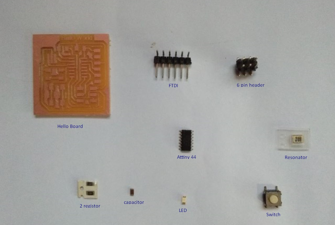
We started with schematic, here add all the components you want in the PCb, in my case I added, capacitor, resistor, two connectors and Attiny 44.For my hello board I added a LED with limiting resistor and a switch. Current Limiting as the name suggests, helps to control and limit the current flowing through the circuit. I used
Ohms' law to find the approx value of limiting resistor. V = I*R.
For the maximun current supported through 1206 LEDs I went through the Datasheet .I think, 10 milliampere is more than enough for any smd led.
Therefore, 5v = (0.01ampere)*R. The value of resistance is 500 Ohms.
Add all components required on board and now time to connect them.
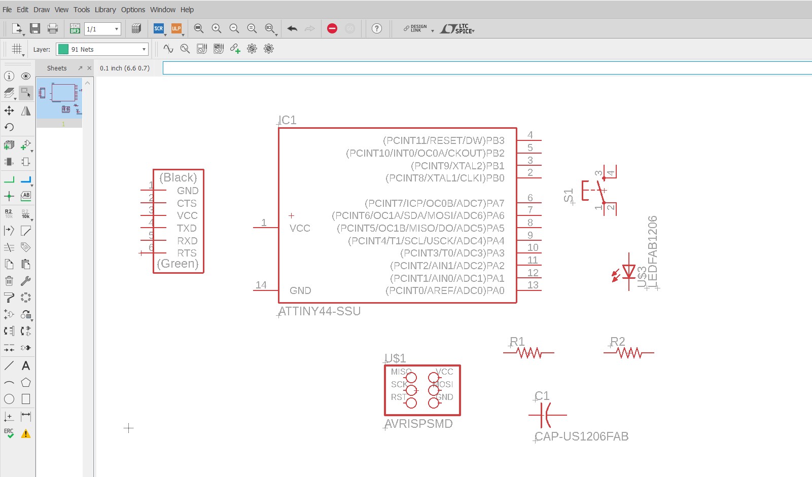
I connected all components by using net(green). If two wires connected in a diagram, it show a dot at the intersection.

Before switchig to board we have to take an ERC, this is a check which will give us warnings and errors related to the elecrical connections.
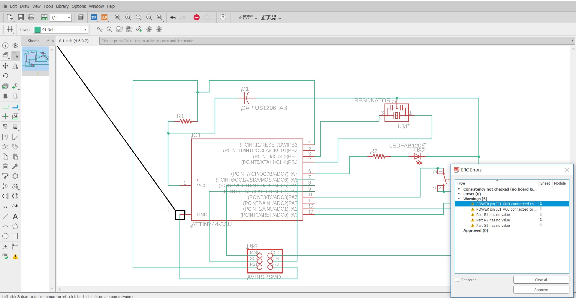
I got Intersection and cross over connection.so,I tried again but with another method.I connected them with names. After finishing schematic design.Clicked on SCH BRD.
now We switch to board in Eagle, All components are outside the boundary which we have to be drag into box.
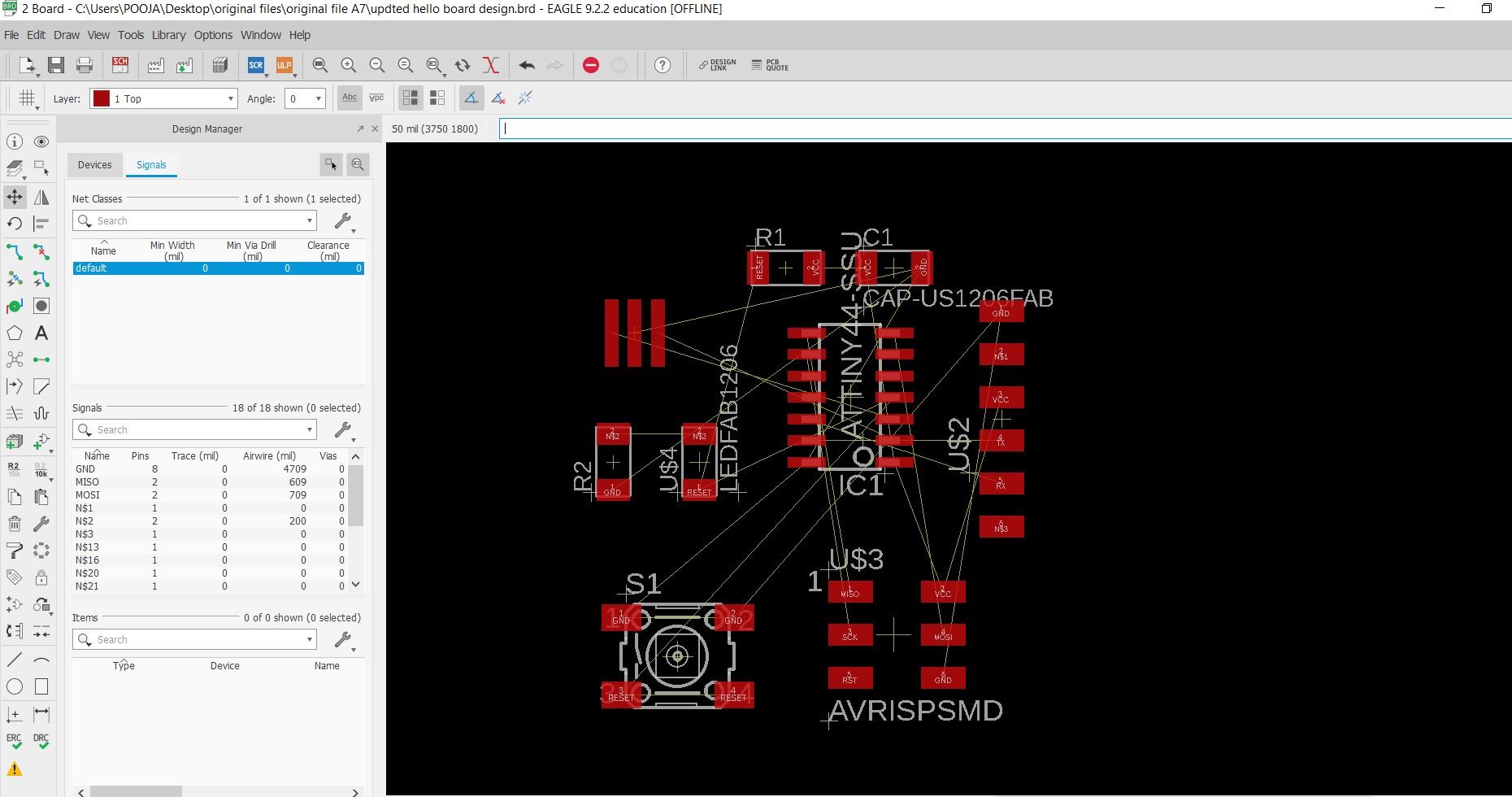
This software has two options for route the board i.e manual routing and auto routing. It all depends on user. I prefer a manual routing beacuse I can't trust autoroute.
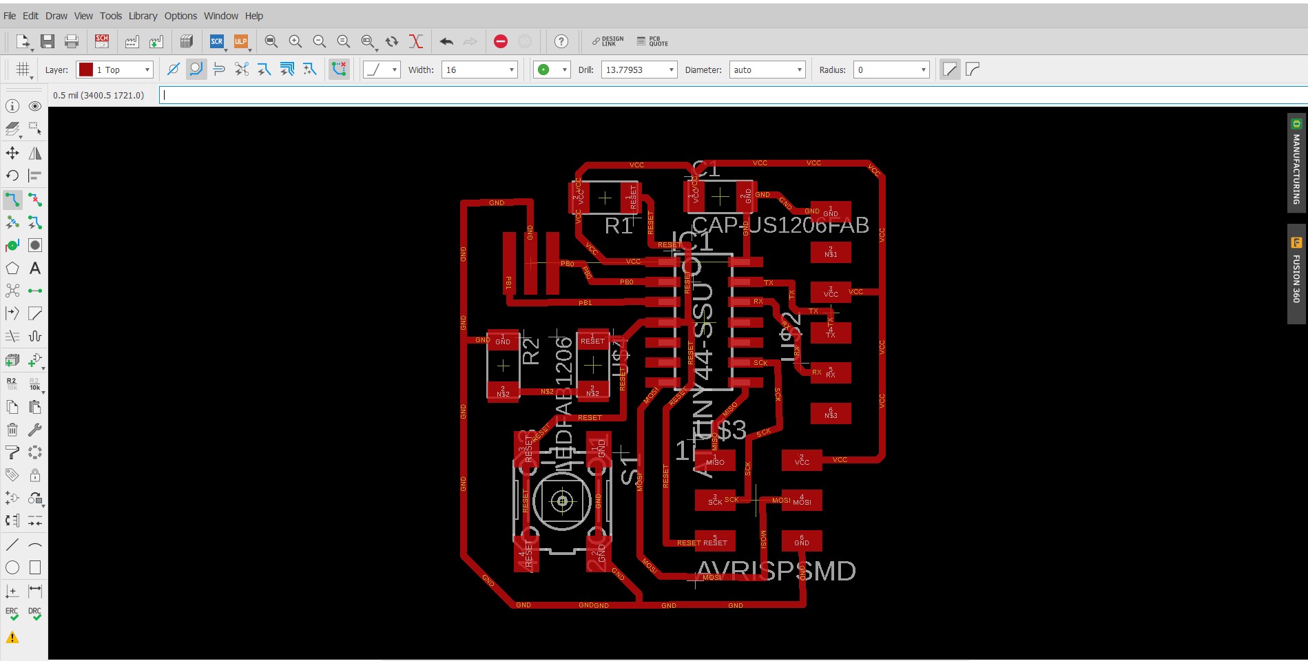
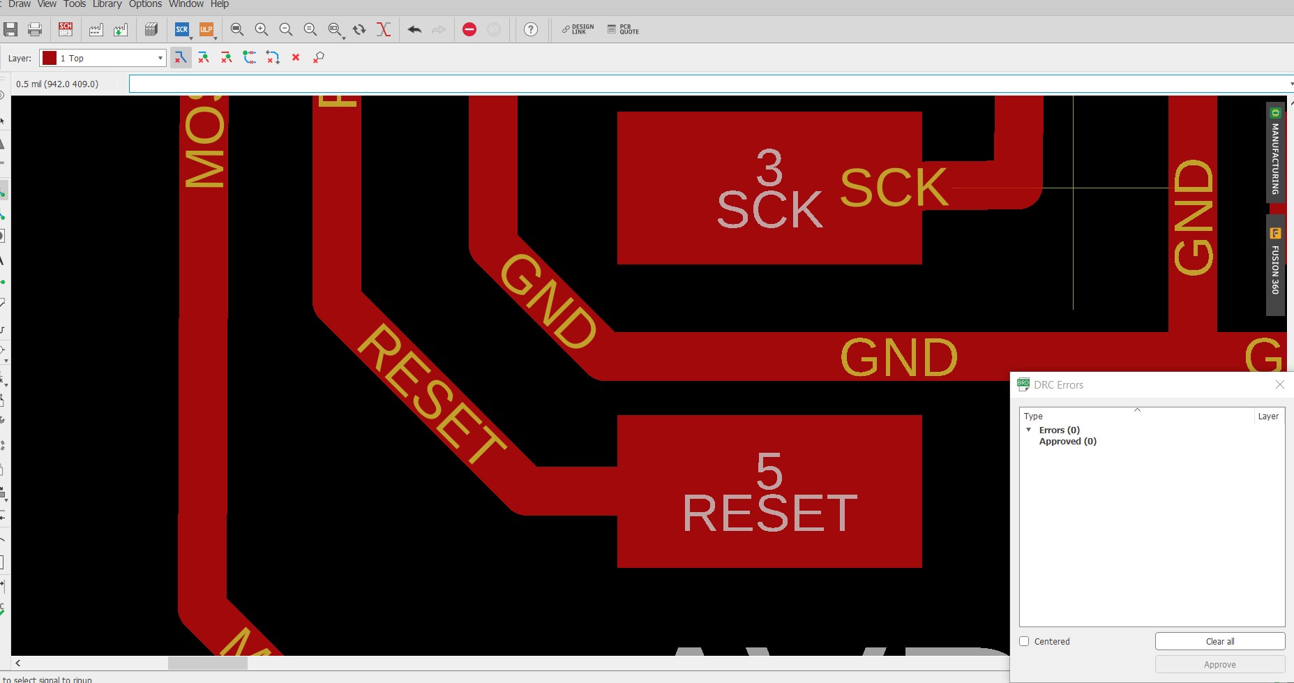
We have to check the dimension and clearance of our circuit and for that click on the DRC.
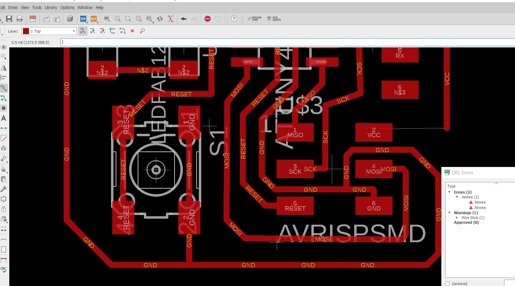
Clear all errors.
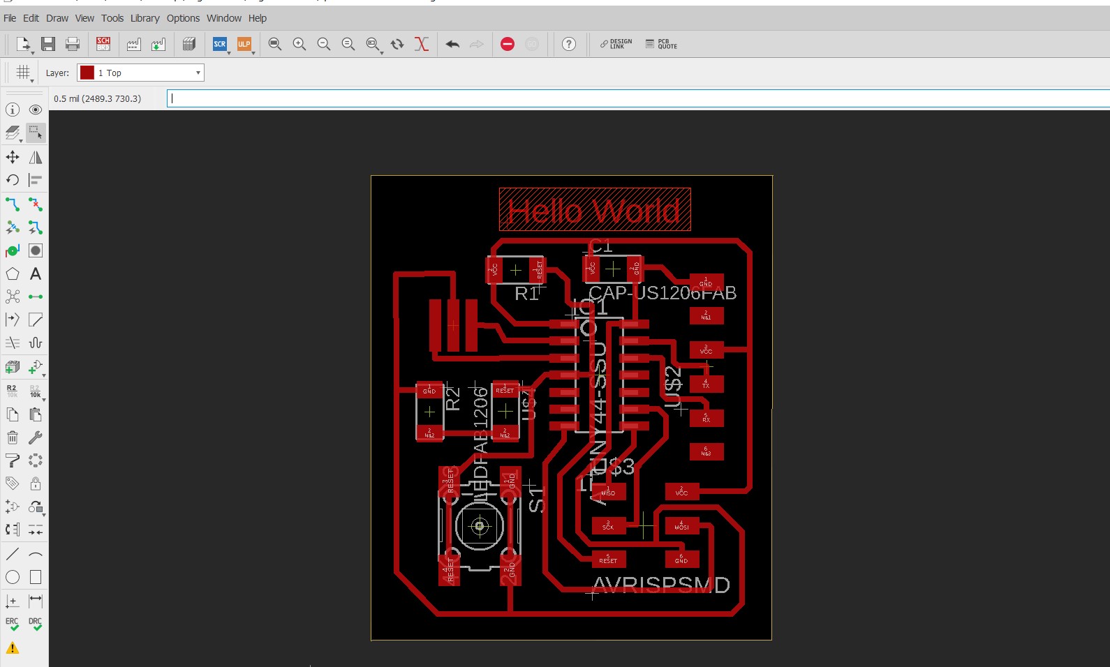
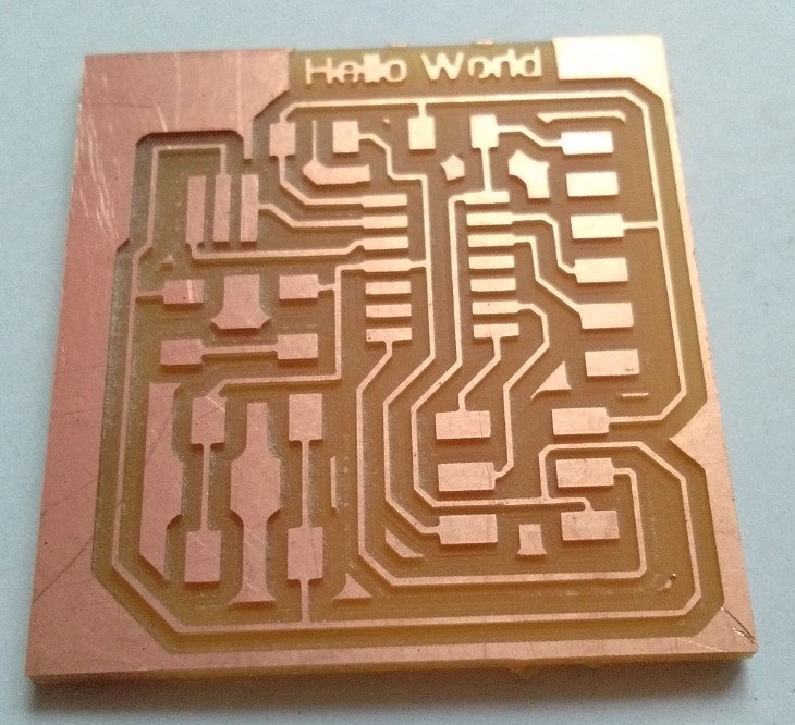
I added some text like "Hello World".
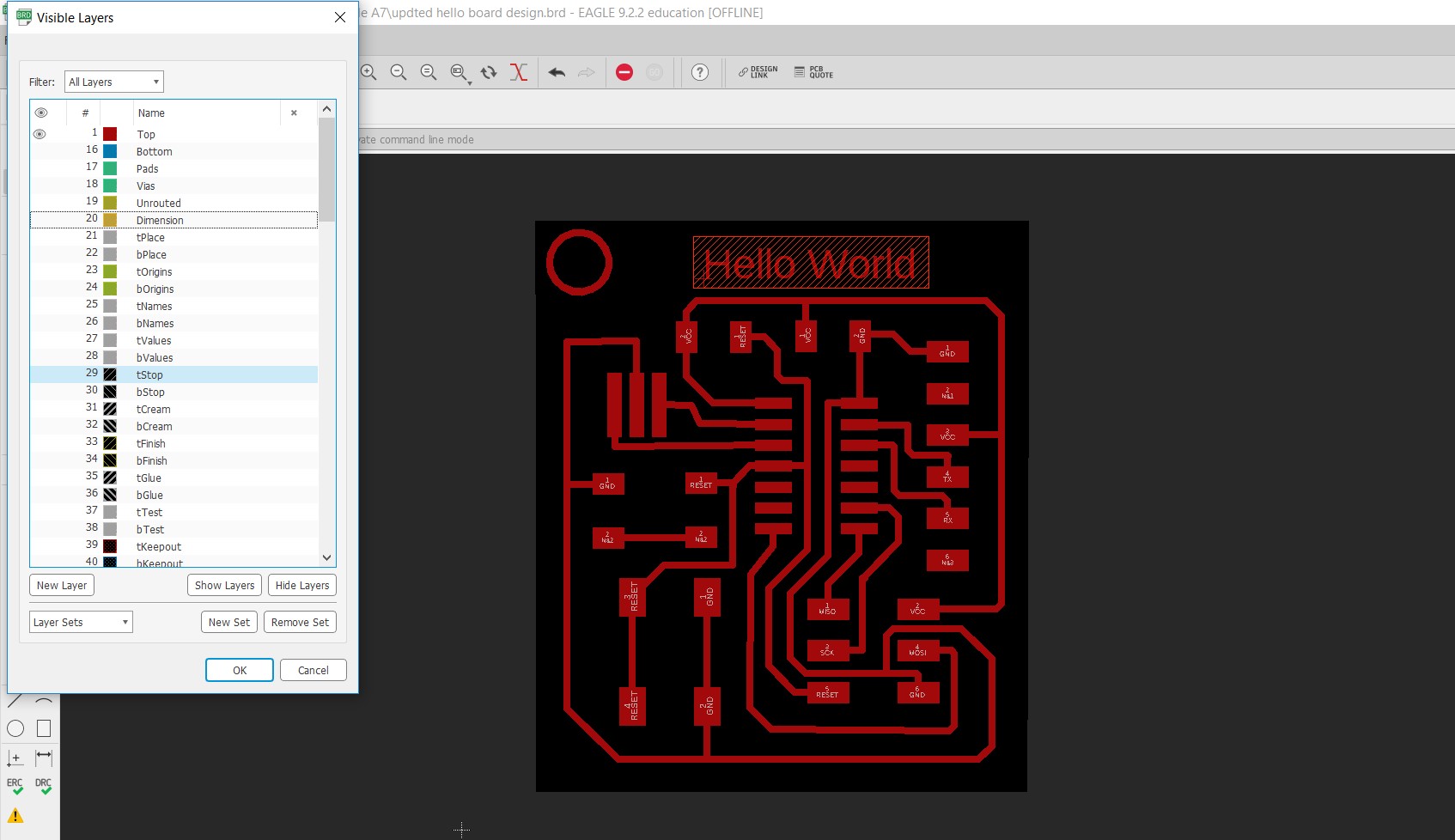
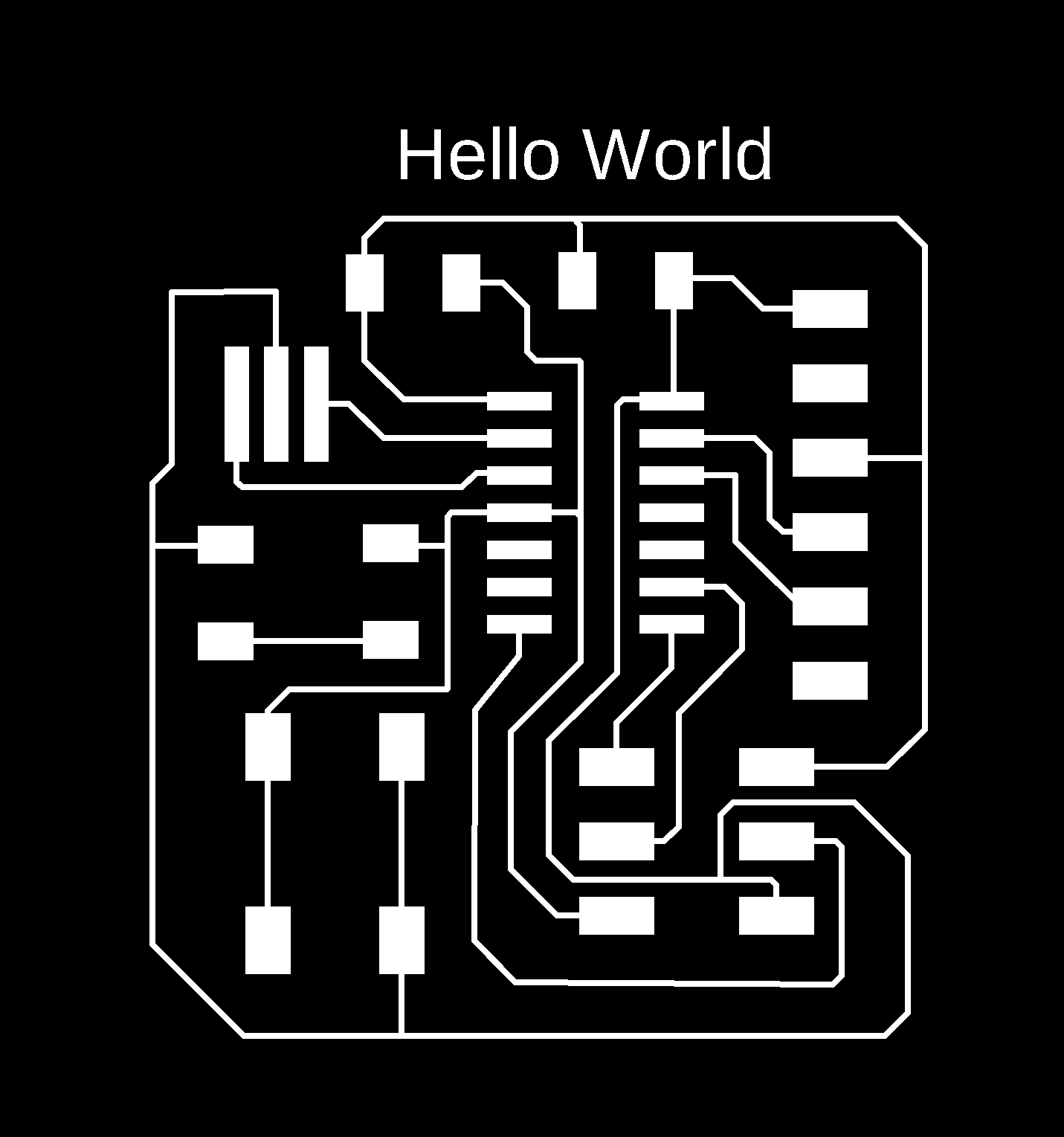
click on layer settings and adjust the dimension layer according to PCB we want. Now we have to save seperate .PNG file for Traces and border. For traces in layer setttings select the Top layer and deselect all other layers.
So,my hello board looks like this....
After completing my board Export file in Image
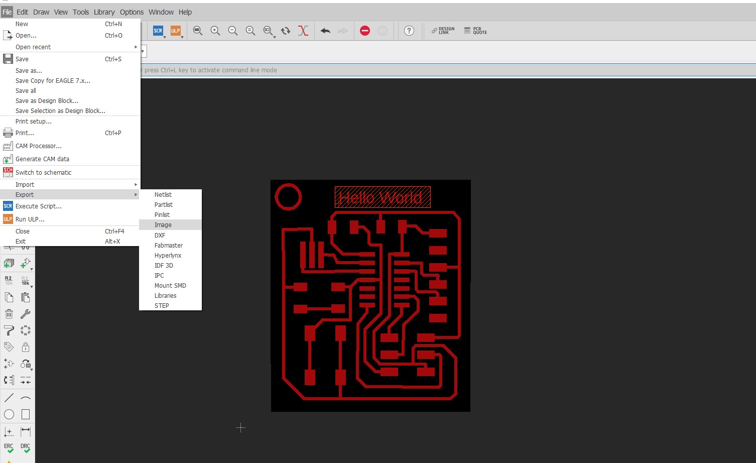
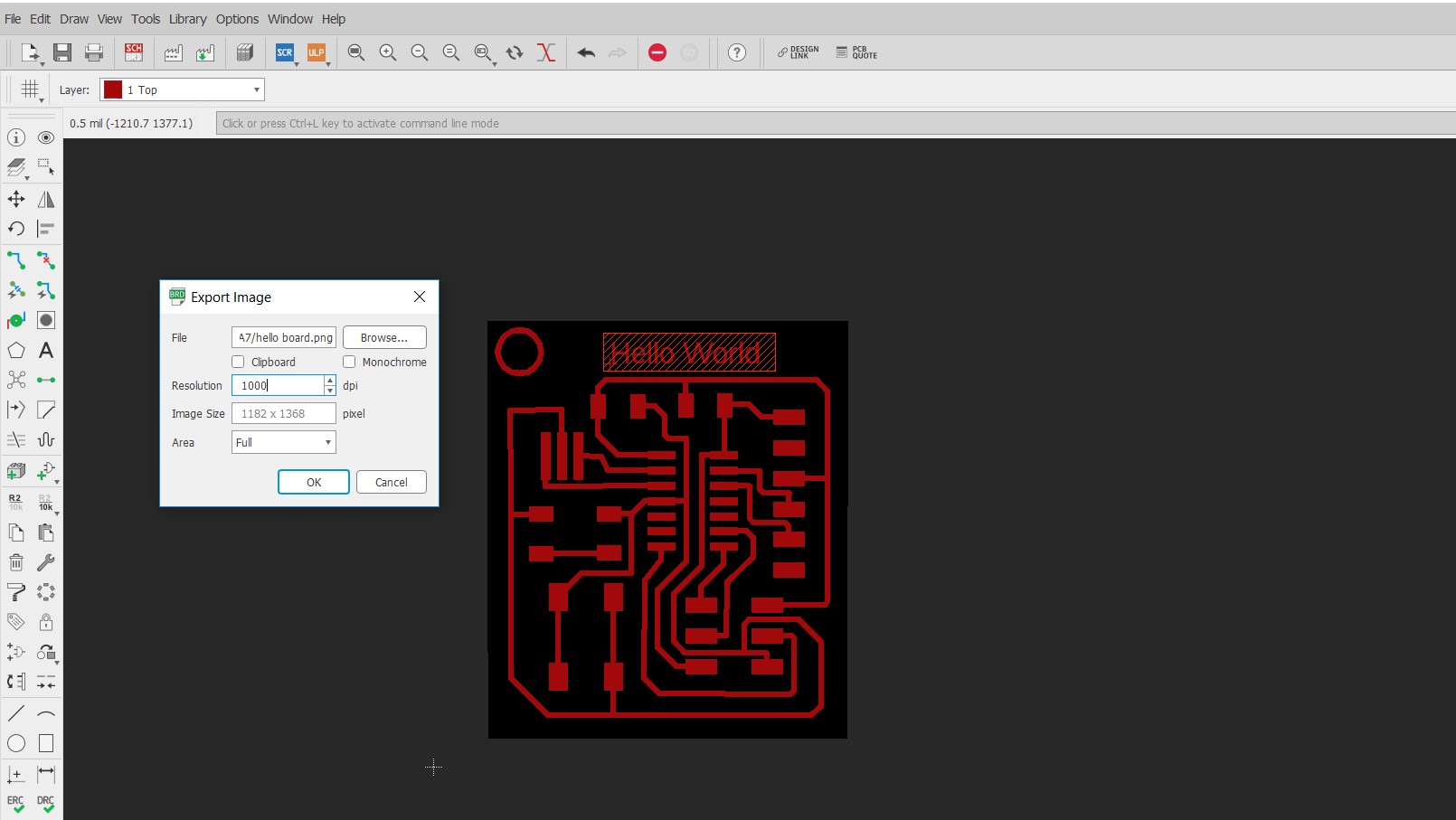
This .png files ready to mill..
|

|
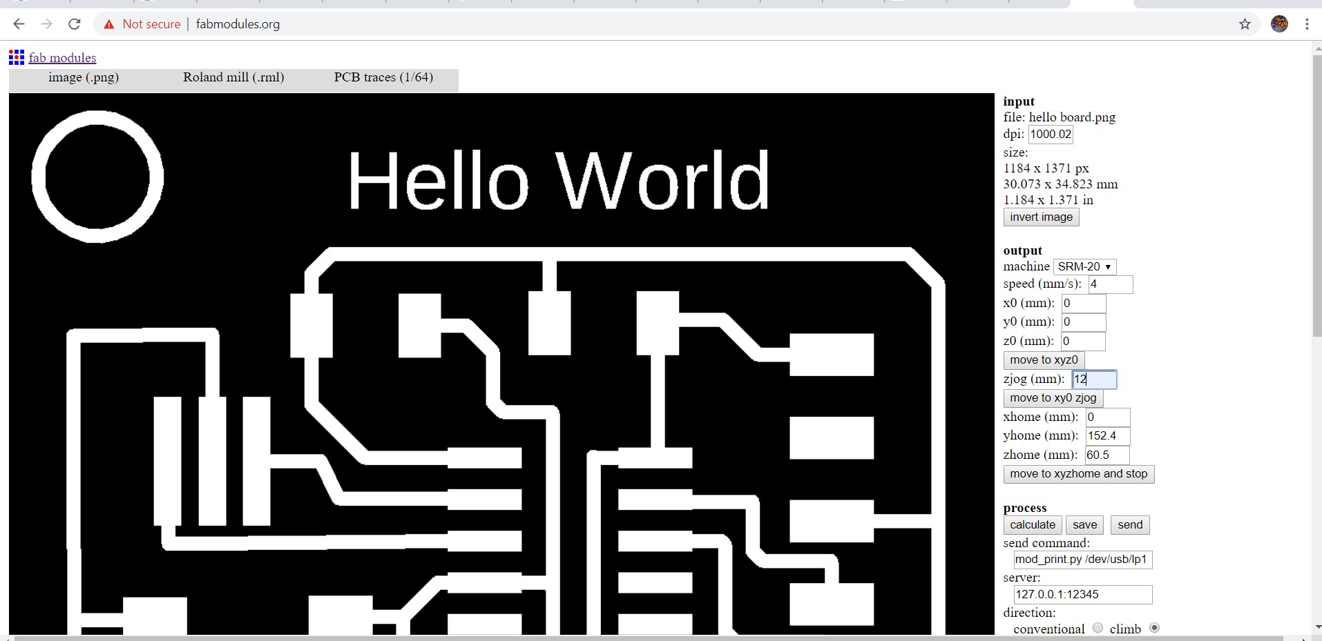
I have .png file which I loaded in fab module and for trace I changed the endmill i.e 1/64 and 4 is offset.
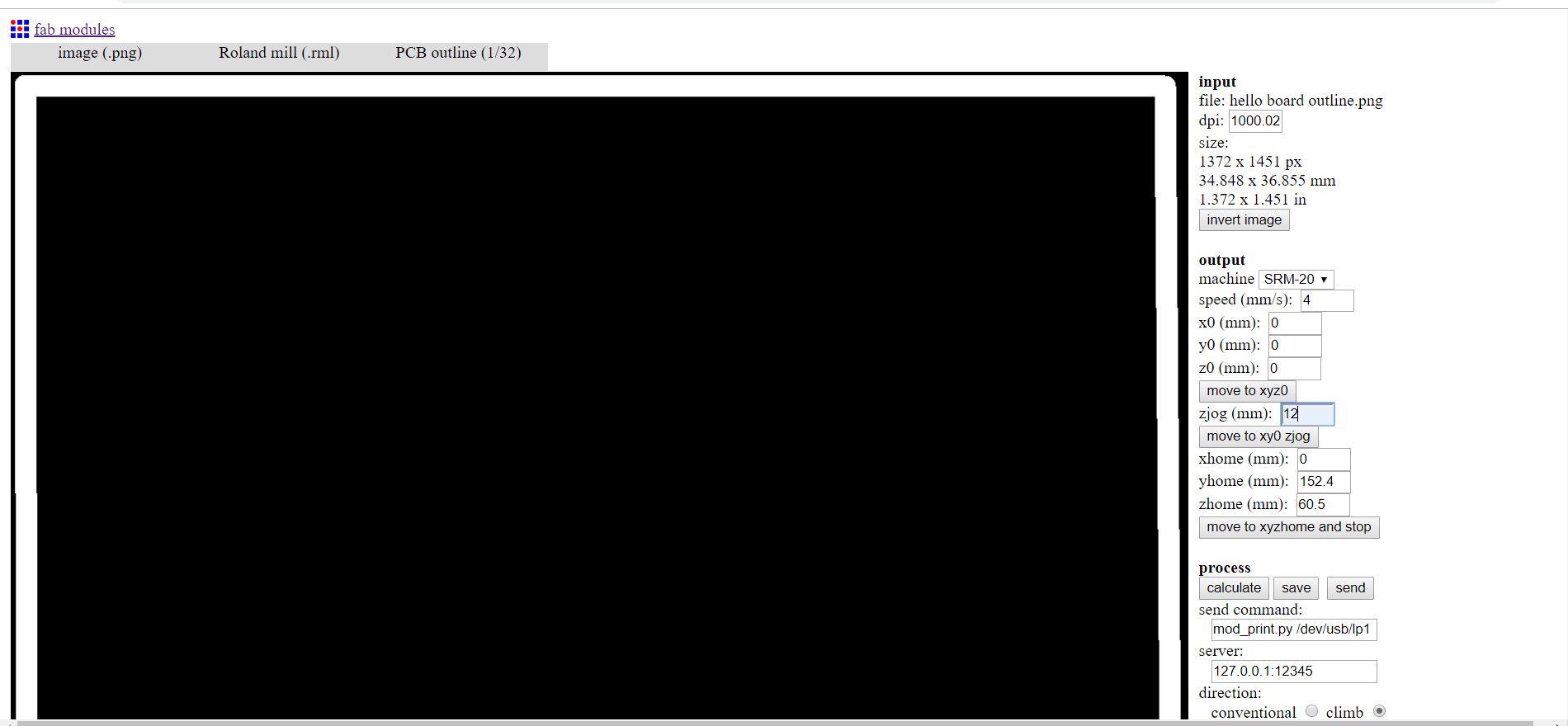
For outline I changed the endmill i.e 1/32 and 4 is offset.
PCB Milling-Hello Board
I study on milling process in electronics production week. So, I started milling my board.First set the origin and gravity.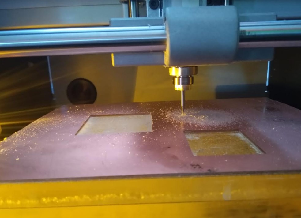
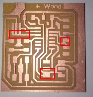
After milling I Checked out my first PCB. It had a track thickness of 0.508mm which was very hard, thus I decided to change the thickness of the tracks. There was no clearance in the paddings of the IC. This time I decreased the trace width to 0.2mm.
Again went back to Machine and began with Milling board.
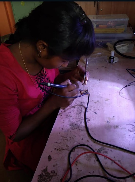
PCB Soldering-Hello Board
I soldered the board and maintain the soldering rules.I collect all the required components i.e
This Components I collected from our fab inventory.
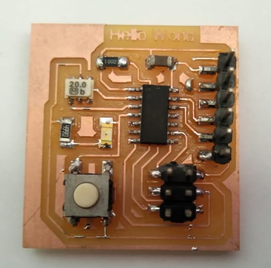
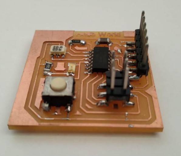
and finally I soldered it.
After soldering....
|
|
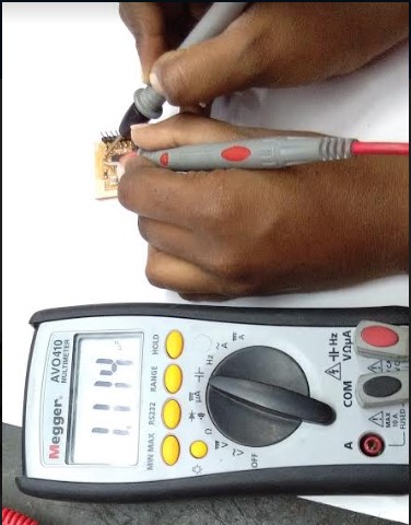
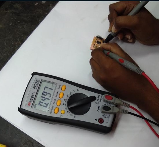
To check all Connections in Board, I check for continuity with the help of multimeter to ensure that the legs had connections to all the traces.
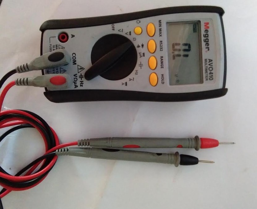
I also check for continuity between VCC and GND. The button's housing is touching the VCC line, but it didn't seem to be touching any other parts of the circuit, so I think everything is fine.
|
|
PCB Programming-Hello Board
Here I used my FabISP for Programming to Hello board.
I program hello board from my fabISP.
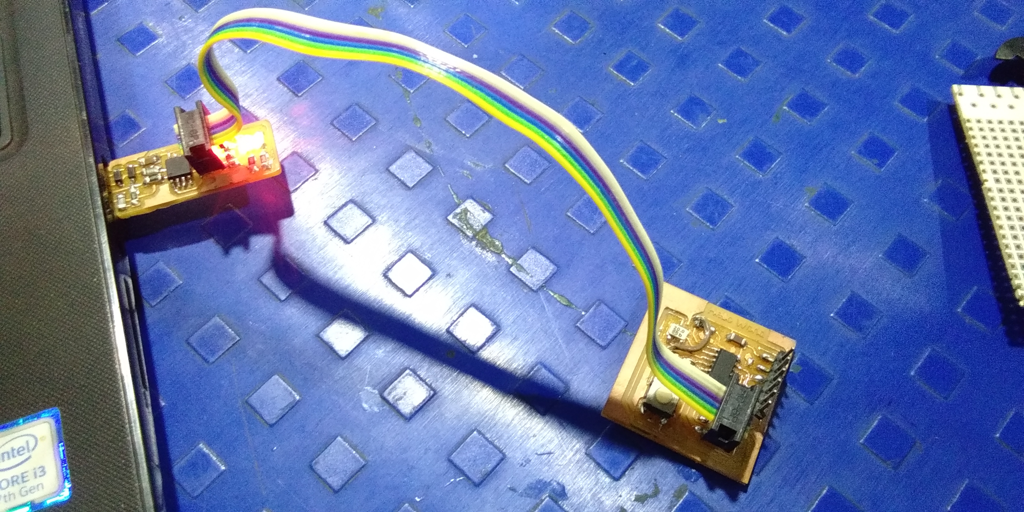
Here,I doing programming on my "Hello echo Board" first step is to make sure that the toolchain are installed i.e avrdude and avr-gcc. Then I downloaded the example code in C and make file and follow the(click here programming tutorial) to compile the code, set the fuses and program the board.
1.make -f hello.ftdi.44.echo.c.make
C code and makefile in my root directory, I compiled the code.so,This Cammand creating a Hex file.

"make -f hello.ftdi.44.echo.c.make program-usbtiny-fuses" for setting up fuses to set external clock of 20MHz.
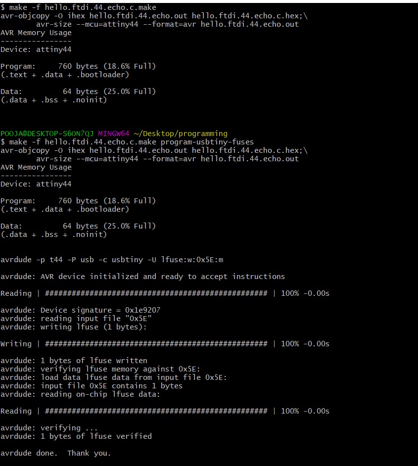
3.make -f hello.ftdi.44.echo.c.make program-usbtiny
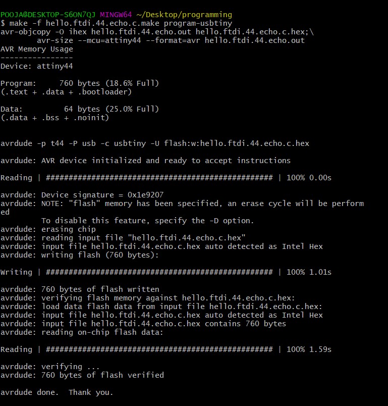
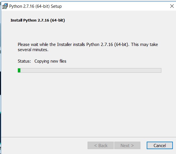
For Python reader,I downloaded and run the term.py file. Changed the parameters accordingly i.e COM8 port ,115200 baudrate.
"Python term.py COM8 115200" this command come up with Error "No module named serial". Okay! I missed one step
Python -m pip install pyserial
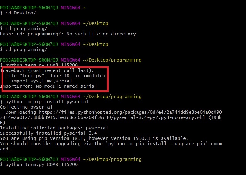
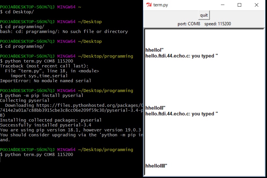
Again I then run this command 3.Python term.py COM8 115200
here is the Output...
Group Assignment
In this assignment we all going to test our hello board with oscilloscope. Monitoring how voltage is passes in the board and voltage curve. Generally the good soldered board give rectangular wave.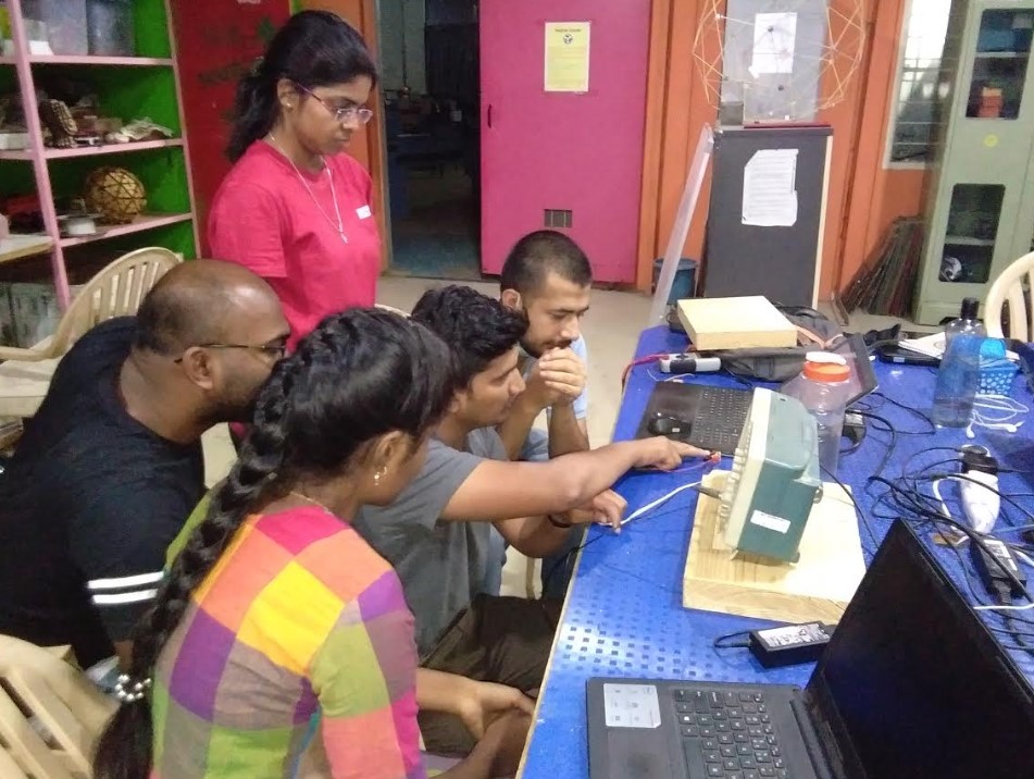
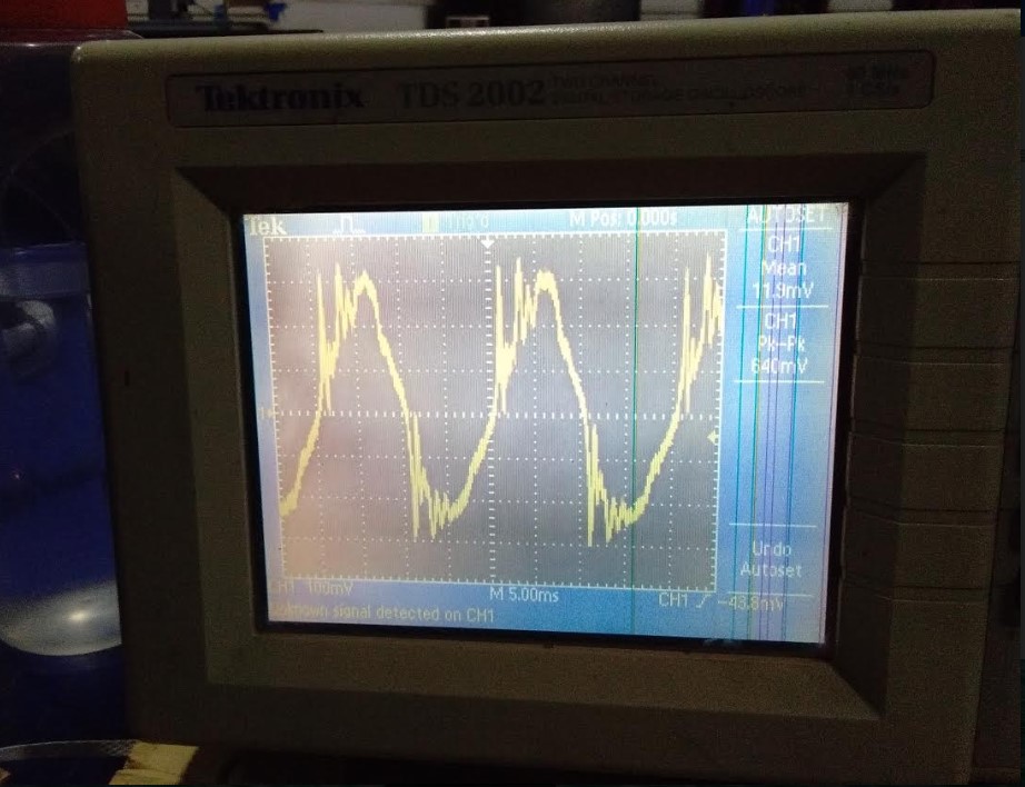
we did a simple testing using DSO, (Digital Storage Oscilloscope). We tested jaydeep's hello world board.we tested resonator on his board.We were observing the voltage curves on his board.Good soldering should give rectangular curve.
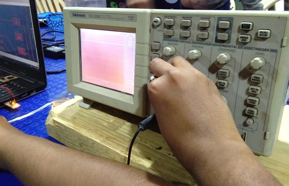
Oscilloscopes are used to observe the change of an electrical signal over time.With the help of oscilloscope we now testing hello world board
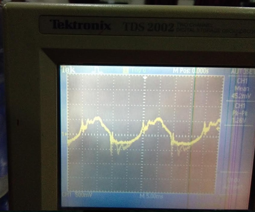
Result show that soldering done well...
You can Download Original Files PNG file
You can Download Original Files Board file