4 - Computer-Controlled Cutting
I Didn't Break Anything Success
Tools & Assignment
 Updated for 2019 evaluation standards!
Laser Cutting
Group assignment
- Characterize your laser-cutter’s focus, power, speed, rate, kerf, and joint clearance
Individual assignments
- Design, laser-cut, and document a parametric press-fit construction kit, which can be assembled in multiple ways. Account for the laser-cutter kerf.
- For extra credit include elements that aren’t flat.
Learning outcomes
- Demonstrate and describe parametric 2D modelling processes
- Identify and explain processes involved in using the laser cutter.
- Develop, evaluate and construct the final prototype
Have you?
- Explained how you parametrically designed your files
- Shown how you made your press-fit kit
- Included your design files and photos of your finished project
Vinyl Cutting
You might make
- stickers
- flexible circuit boards
- a textured surface/relief pattern
- screen-print resists/stencils
Learning outcomes
- Identify and explain processes involved in using this machine.
- Design and create the final object
Have you?
- Explained how you drew your files
- Shown how you made your vinyl project
- Included your design files and photos of your finished project
(Copy of my 2016 website, with spelling corrections :)
Preamble
Before this week the vinyl cutter and laser cutter were Alien to me.
Like the second week, my CAD of choice is Antimony.
I knew that I wanted to create something resembling my project, so I decided to settle on cubes.
[Download links to my files as last paragraph]
Our Third Lecture
After the first half of “random-student-picking” Neil Gershenfeld explained to us the functions and hazards of the vinyl cutter and laser cutter, the precautions to take and helpful tips to improve our work.
The Vinyl Cutting
Going home after the introduction to the machines by Cecilia I already knew that I was going to make a sticker for the back of my main Apple PC.
The sticker was going to be a representation of a Japanese animated series name Fullmetal Alchemist (which holds a particular emotional value to me), in particular a photo of a broken (robotic) hand reaching for a red stone.
Original Image

So I got to it immediately, the task was quite difficult since my intentions were to make a three-layered sticker from a colourful image.
The base was going to be black, the main body in grey, while the points of light and details in white.
The Design
-> I downloaded Adobe Illustrator CS6
-> Opened the original image in Illustrator
-> Opened image trace from the window option
-> Selected ‘high fidelity trace option
-> Expanded the traced image
From there I proceeded to remove all the layers (by hand, one by one) of colours which I didn’t want for the base and exported the file as PNG.
I re-opened the newly exported PNG and re-traced it, to make the lines more solid and smooth, adjusting the settings of image trace to my liking (I chose the option 3 colours ) and exported the final desired PNG.
Layer One

I repeated the same process for the other two layers.
Layer Two

Layer Three

Then used the application preview to juxtapose them, resulting in what the sticker should look like once completed.
Overview of Different Types of Laser Cut Parts

The juxtaposed png layer using ‘Preview’ & what I hope the final result with look like
-> Open Illustrator on that computer
-> Import the PNG
-> Once again trace with preferred settings (I used ‘3 colours’)
-> Make sure there are no double line! (I fail badly here because I imported the .ai files instead, it took me about one hour before I managed to do a proper cut)
-> Send to the vinyl cutter to print after adjusting width and length of the image (Which you can get from the vinyl cutter through the preferences)
Using The Roland Vinyl Cutter
This video was really useful for me to understand how to use the vinyl Cutter -> Vinyl Cutter Roland GX-24 - How to Use
I. Check if the blade is clean
II. Turn the machine on
III. Load the paper piece or a roll in the machine
IV. Insert through the vinyl cutter and adjust wheels must always be on the white spaces and always within half a centimetre from the edge of the paper
V. Select on the menu whether it will be a piece or a roll.
VI. Press enter and let the machine measure the pieces length and width (only width if it’s a roll)
VII. The machine is ready to receive the files.
Cut Settings
- Speed:
10cm/s - Force:
100
Transferring The Cutout
The standard method to transfer cutouts is by using transparent transfer film. This is similar to the vinyl itself, and it’s applied directly on the cutout (sometimes after removing the surrounding material).
Because the transfer film has (weak) glue, it will attach to the vinyl, and once lifted it will expose the glue (sticky) face of the vinyl, which you can then apply to the desired surface.
The glue that holds the transfer film to the vinyl is weaker than the one on the vinyl itself, thus once the cutout is applied you can peel the transfer film, and the cutout will remain on the desired surface.
Overview of Different Types of Laser Cut Parts

A photo of the first layer applied to the back of my MacBook
Laser Cutting - The BRM Laser Cutter
The laser cutter I used to create the cubes is a BRM, particularly the BRM1612, which I can’t link to since I can’t find it on the BRM website, the most likely reason for this is that it’s out of production, but is comparable to the BRM 100160 considering they have similar work-surface dimensions.
The work-surface dimensions are: 1200 x 1600 x 300 mm, the z-axis is fixed during jobs but is adjustable up to 300 mm to accommodate for materials of different heights. (This machine seems to exist only in de waag, since I can’t find any other references to this machine :)
It’s equipped with a 100W, CO2 laser.
It runs using the software Lasercut (5.3)
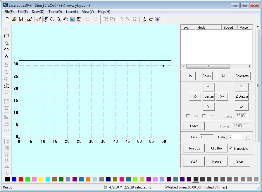
Image credits: smokeandmirrors
Finally, the working material with which every student was provided was 1000 x 14000 x 3 mm cardboard.
Characteristics - Manufacturer defined
- Focus:
12.10 mm(if what we mean is focal distance) - Power:
100 W - Rate (of feed): ? feed rate usually is defined by revolutions per minute, which doesn’t apply here, can’t find any other forms of rate.
- Max speed:
400 mm/min(cutting)
Characteristics - Experimentally deduced
- Kerf:
0.15~0.25 mm - Joint clearance: Not known (not calculated & not found)
Using The Machine
Rule No. 1: Never leave the laser cutter working unwatched
Rule No. 1.5: Turn on the ventilation when the laser is running
Rule No. 2: Don’t keep the laser & ventilation on if you are not using the machine
Rule No. 3: Wait a minute before opening the laser cutter to retrieve your work to let bad smell ventilate out
Rule No. 4: Measure the distance from the surface which need to be cut and adjust it as necessary using the wooden ruler
Rule No. 5: Weight down any elevated surface to avoid contact with the lens of the laser
Rule No. 6: Don’t put the weights in the way of the laser (Do a test run to check it does not)
Rule No. 7: Be on the ready for fires, keep water spray near by, press stop & don’t panic
Note 1: Software LaserCut5.3 only accepts .dxf files (not sure if this applies in 2019)
Note 2: Don’t forget that the laser will cut away part of the material, thus you must increase the size slightly to make sure your parts fit (adjust for kerf)
Note 3: Delete all when downloading your files to the laser to make sure it erases previous work
Note 4: Do a ‘test’ run to check the area of your cut to make sure the size is about right
Note 5: Adjusting the power and speed is necessarily for each material e.g. power: 50% & speed: 100% is good to cut cardboard
The Design
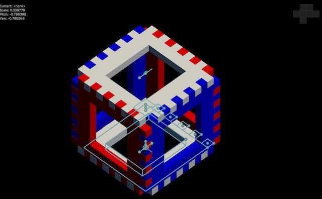
I wanted to make cubes that could be constructed and joint so that they could take on any form, the tricky part in this is making sure the cubes are solid, and find a way to connect them that CAN be taken apart when you want to change the configuration.
I settle with a connecting and locking system where two different cuts in the surface of each facet allowed for two types of hinges to be inserted, one that connected two cubes and one that locked the connector hinges, which are perpendicular to them.
I designed all my parts in Antimony, because you got to admit, it’s just that awesome.
In week03 I designed the basis of cube that I will be using this week, in this week I added the hinges and connections.
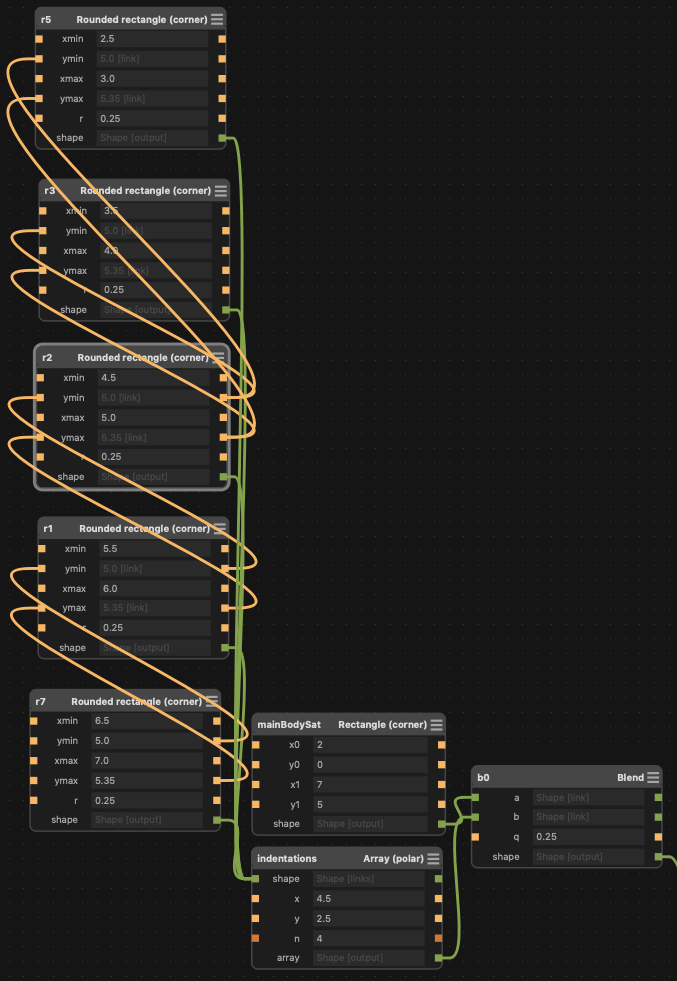
Parametric Design
Antimony is inherently parametric, since designs are created using nodes, which are visual representations of mathematical functions, meaning everything is defined algorithmically (thus it’s parametric).
Furthermore nodes can be linked to inherit properties of other nodes, meaning parameters of the design are globally defined and updatable.
Antimony is split into two screen, the 3D model (output) viewer window, and the graph window, which holds your node tree and parametric input.
Week03 Assembly Test
Antimony Quad Window to View All Sides
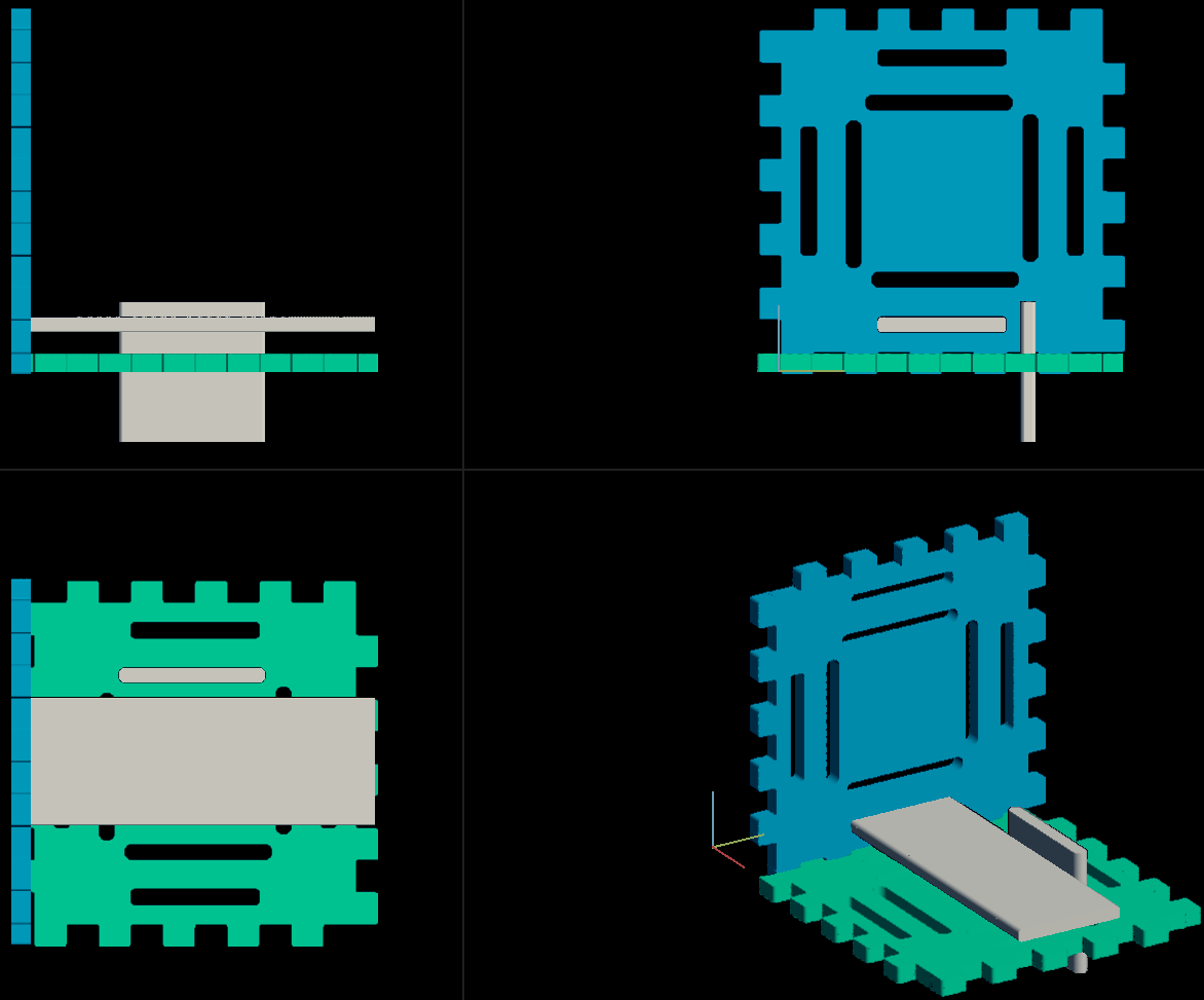
Main Body of Cube Face Design
The 3 files included all share a similar design to the above.
Notice that the cubes have a perfect fit, if the dimension were perfect, it would be quite difficult to fit this model, but because we can expect some material to be lost on the edges due to kurf, we can use that to our advantage and let kurf introduce the required tolerance for a better fit.
However, one thing is a better fit, another is a loose fit. This is where creating multiple cubes with slight dimensionality increases come in handy, from having the second last slot I knew from previous students that 0.15 mm was a workable kurf, thus of my 5 cut cubes in the range 0.14 mm to 0.18 mm kurf all fit well (except for the under-scaled one), with some help needed by the 0.14 mm & 0.15 mm cubes from the locking hinges because it they were a bit too loose.
I used the export as height-map function, which essentially exports a png file using the top view as reference. Then I opened it on Adobe Illustrator, imported and traced the png files, and exported it as a .dxf.
I checked the scaling and if it worked on my Windows PC by installing the LaserCut software on it. I had big issues with scaling and figuring how to measure the parts correctly, eventually I managed.
I made two design, each one only need one part (facet) to construct an entire cube, the difference was mainly with the size of the indentations and the amount of gaps in the facets.
I created a total of four cubes, with the intention of making five, but the fifth was composed of facets so small that the indentations where not deep enough to interlock. Note to self, the indentations must be at least 3mm thick, like the cardboard.
I wish I could have spent a bit more time on the machine, because I have had problems with scaling my designs, however I am quite pleased with the fit I got so far, but still want to improve it.
Facet Type A & Connector Hinge: Height-map
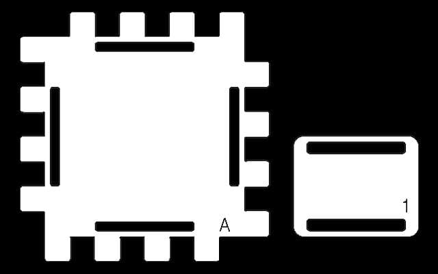
Type A facet, with less cuts and the one which ended up creating the best fitting cube due to the dimensions of the indentations. The type 1 (connector hinge is the same for both facets and connects two cubes.
Facet Type B: Height-map

Here I didn’t write a letter since letters do not do well with ‘image trace’ and I can add them in the LaserCut program really easily. This is the type B facet, it accommodates two different types of cuts, the larger one is for the connector while the smaller one is for the locking hinge.
Locking Hinge: Height-map

This is, quite frankly, a simple rectangle with precise dimension that slides from one end of the cube to the next. These connect two parallel facets making the cube more robust and secure the connector hinges. It is also simple to remove by just pushing from one end.
Loading the files
First I loaded the cardboard within the laser cutter, making sure it was held down as specified in the rules, and turning the machine on, which is done by activating the start buttons on the dial in the same order as the stickers beneath them
BRM control panel
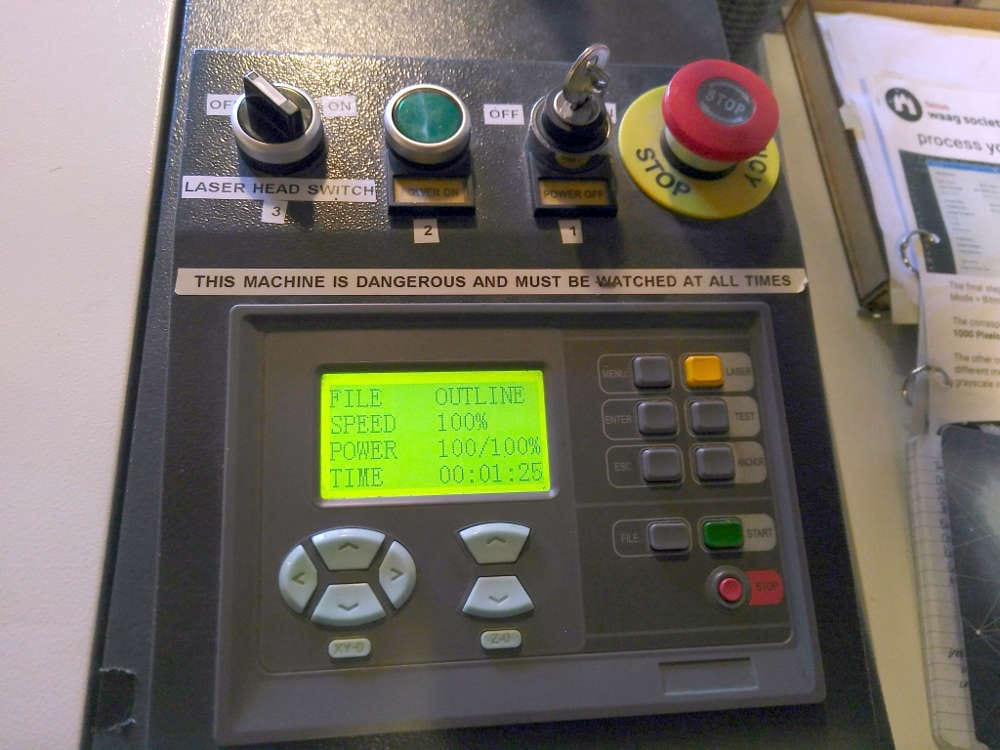
The extractor is activated by activating the green switch (which will turn bright green when on) and setting the fan speed to maximum.
Using a USB stick I uploaded the files to the computer, imported them onto LaserCut, adjusted the scaling, power and speed. Then downloaded the file to the laser.
Speed & Power Settings
- Power:
50% - Speed:
100%which is400 mm/min
On the laser you set an anchor point where you prefer, test to see the area it covers, and focus the laser; this is delicate, as it requires the lens to be slightly loosened, brought to level with the 12.10 wooden levelling template, and locked again into place.
Finally, close the laser, select the file, check that all the rules stated above are clear, and enter to start....
Watch intently at the beautiful, addicting laser and see it do it’s magic.
You should not do this if you are keen on keeping your eyesight
2019 Update
Since 2016 I’ve not used laser or vinyl cutter.
The main reason for this being that here in Manchester FabLabs are pretty scarce, and laser/vinyl cutters are large and expensive specialized machines that I could only find in a FabLab. Unlike, say, a 3D printer or desktop CNC milling machines.
As a consequence of this, my proficiency in this field has steadily decreased, which is sad considering that laser cutters are some of the most useful tools in a fab lab.
Home FabLab’s & Lasers
Coincidentally, the laser cutter is one of the tools found in a FabLab that is hardest to bring to the consumer market, the high risk inherent in these machines make them impossible to own in a flat or a in a house without a shed/garage.
The ones available use fairly weak lasers that can’t cut through thicker materials (usually branded as engravers), and pose serious health risks.
Gallery 
Overview of Different Types of Laser Cut Parts
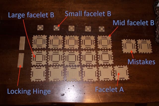
In this illustration you can see labelled each different part I cut, and which I mentioned above.
The Cube Made From Putting Together Type A Facets
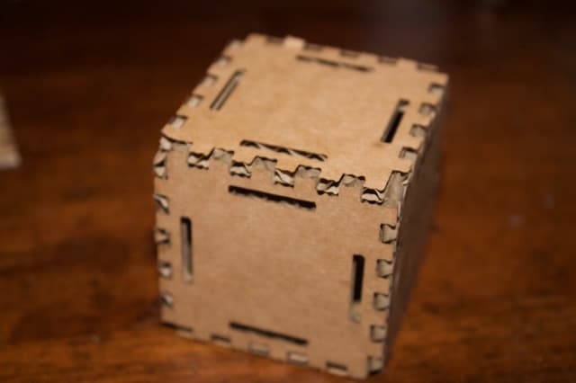
This is the most solid of the two types of cubes, most probably for the fact that the indentations are slightly larger then Type B.
The Cube Made From Putting Together Type B Facets
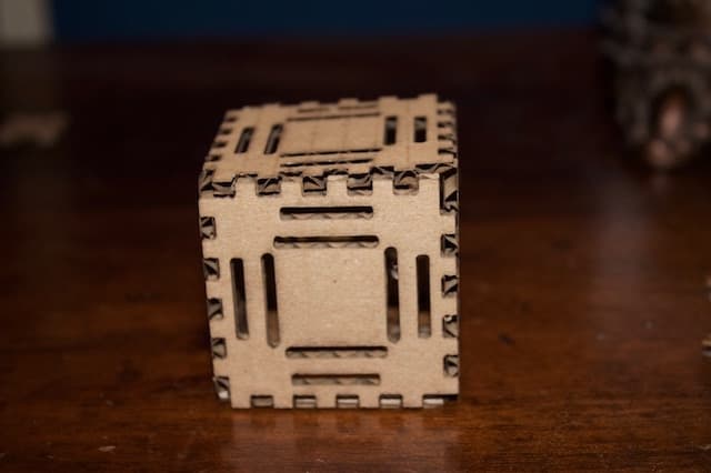
This was the least solid of the two types of cubes, but was the most functional, the different sized holes made it easier to connect to other cubes.
Conjunction of Assembled Cubes
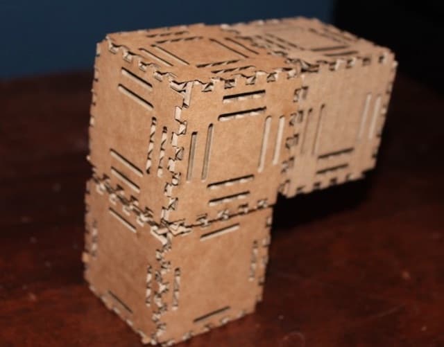
A connection of the few cubes I constructed; one type A & two type B large and medium size, which I connected using the locking hinges (which are not what they are meant for but they worked pretty well). It was a solid structure, the hinges where a bit short and the type B cubes slightly fragile.
Download The Files
-> Zip With DXF Files
-> Zip With Height Maps
-> Zip With Antimony Design Files