16 - Interface and Application Programming
The Pretty Side of Life
Tools & Assignment
 Updated for 2019 evaluation standards!
Tasks
- Write an application that interfaces with an input and/or output device that you made, comparing as many tool options as possible.
Learning outcomes
- Interpret and implement design and programming protocols to create a Graphic User Interface (GUI).
Have you?
- Described your process using words/images/screenshots
- Explained the the GUI that you made and how you did it
- Outlined problems and how you fixed them
- Included original code (or a screenshot of the app code if that’s not possible)
(There is a 2016 page, but it’s worthless, let’s start anew! :)
CapSensing & Visualizations
At the end of week11 I left you with a rolling numbers that increased when the sensing pad was touched.
These were streamed to the serial plotter following this flow:
CapSense Board->Arduino->USB->Arduino IDE
We can keep the same device interface, because we’re working with Arduino IDE the logical software to use is Processing, which are highly symbiotic.
Processing
To get started we need to download Processing, which I did by running:
brew cask install processing
Once that’s done, we can open it up.
We know from week 9 that we can communicate over the serial port at baud 9600.
Thus we need to find out how to read serial data in processing.
A quick google search of processing serial returns this -> Processing reference manual
Let’s go ahead and copy paste that code into a sketch aaaaaand lets stop here.
Some Thoughts
Okay, processing seems like the standard and easiest route that most people choose to take, but as I tried to get it to work, it was just too impractical.
Firstly, I don’t like Java, no hate, just personal preference. So I tired doing it in Python, since Processing permits it.
However that was a challenge seeing that most documentation is in Java, I got it to work thanks to these two links:
However it was shabby at best. Lets be honest here, the whole system we constructed to help us start off, on the long run is a dead weight!
At some point I just said, “hell to this” and decided I was going to do it with native Python, not some dumbed down version made for Processing.
My current full time job is in machine learning, and Python is the main language used in this field.
Thus, I maybe be cheating, but full Python is easier for me then simplified Java.
PySerial
This is where everything begins and ends.
This Python library lets us communicate with serial ports, in our case it will be the USBtoUART-chip-thing which is the low-cost version of a FTDI cable
Installing
We can get started by installing PySerial, I use Anaconda so my install command is:
conda install -c anaconda pyserial
If you want to install using pip then the command is:
pip install pyserial
Setup
Getting start with PySerial is fairly easy, according to this link:
import serial
ser = serial.Serial('/dev/ttyACM0')
ser_bytes = ser.readline()
Imitating Serial Monitor
In actuality we want something a little more nuanced.
Our first goal is to create our own serial plotter like the one we see on the Arduino IDE.
We being the Python file with a shebang, some imports and global constants:
#!/anaconda3/envs/py37/bin/python

import glob
import serial

AR_PORT = "usbmodem"
FTDI_PORT = "SLAB_USBtoUART"
BAUD = 9600
TIMEOUT = 1
Then we do some automation, we can list all connected devices using:
def serial_ports():
    """ Returns available ports """
    ports = glob.glob('/dev/tty.*')  # MacOS port pre-fix
    result = []
    for port in ports:
        try:
            s = serial.Serial(port)
            s.close()
            result.append(port)
        except (OSError, serial.SerialException):
            pass
    return result
This code iterates through all directories found that match /dev/tty.*, which is the standard for MacOS device files (not really files, more like file-like access points for external hardware), attempts to connect and in the case of success closes the connection and adds the directory name to the list, in case it can’t connect, it will raise an OSError, meaning it’s not a connectable device, which shouldn’t be added to the list;
credits.
We can connect to a device, given a port name (as string), using:
def establish_connection(port):
    """ Returns serial connection & status"""
    print("Connecting to {}".format(port))
    device_ser = serial.Serial(port,  BAUD, timeout=TIMEOUT)
    return device_ser
Here the majority of the functionality is given to serial.Serial which initializes the connection, and returns an object we can read bytes from.
BAUD, timeout=TIMEOUTisn’t a necessity, but good practice
Our main function, look like this:
def main(device_port=FTDI_PORT):
    # -- Get available ports & connect to Arduino --
    ports = serial_ports()
    device_found = False

    for port in ports:
        if device_port in port:
            device_found = True
            device_ser = establish_connection(port)
            break
        else:
            pass
As input it gets a device port, which is a string containing the name of the port you’d like to connect to.
In the for loop we are iterating through each available port in the list of ports, that’s straight forward.
However, the subsequent if statement is designed a little strange.
What we’re doing with if device_port in port: is simply checking if the string device_port is present as a substring of the string port.
For example, if we have the word apple and we run if apple in pineapple it would return True.
This lets us define general names such as usbmodem and match no matter what the full string is.
This is handy because depending on the port, the Arduino name may change, or if you have multiple Arduino’s, or different devices altogether we can connect to them directly without looking at the name, or relaying on the fact the usually connect on index 0 (which somehow seems to be a favorite amongst tutorials, if I did that I would connect to my Logitech mouse!!!)
After checking that we connected:
    if not device_found:
        print("Device not found, PORT name is wrong?")
        exit()
    else:
        print("Connection established")
We can start reading bytes from the device with:
   device_ser.reset_input_buffer()
    while True:
        try:
            ser_bytes = device_ser.readline()
            print(ser_bytes)
        except KeyboardInterrupt:
            print("\t Keyboard Interrupt")
            break
This will constantly read lines from the serial device, printing them to the console until ctrl+c stops the program.
Anyways, the first thing to do is make that output a little more readable:
print(ser_bytes.decode("utf-8")[:-1])
[-1] at the end removes the newline char \n at the end of the string.
We run the program, let there be numbers:

We can get also a more reasonable range of number by having a math.log10() operation.
We add import math then:
value_as_int = math.log10(int(ser_bytes.decode("utf-8")[:-1]))
print(value_as_int)
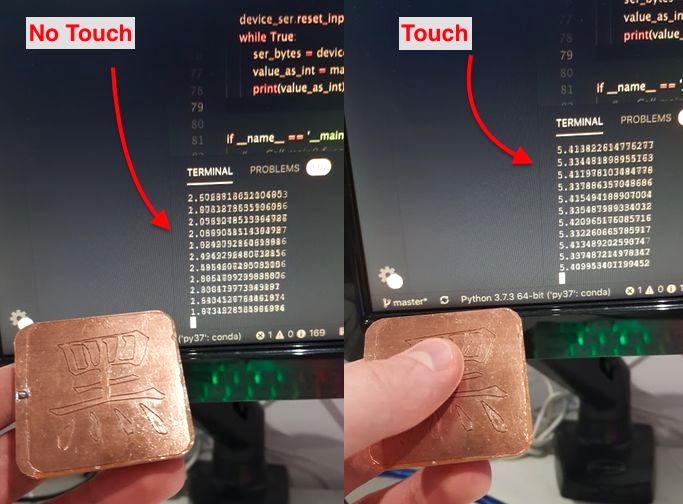
Looks like values around 2 are when the sensor is idle, 3 is for light touches and 5 is heavy presses.
Not sure where 4 went, I guess (s)he has it’s own plans and dreams.
Important Note
One thing to note, which caused me lots of pain was the fact that PySerial won’t start reading the bytes until it gets a newline char \n.
This means that the code you upload to your device must contain some Serial.write("\n")
Credits to dhunt from this forum
GUIifying The Data Stream
Okay, that’s nice and all, but we only got a serial monitor going. Next step is to plot those values.
We could have:
- a single progress bar displaying the latest value -> Is this better then serial monitor? Not really
- a time/value plot
- a gauge bar -> No way, not worth it
- a boolean
on/offbutton
Python Drawnow
For the last, python-drawnow looks cool.
Installing
pip install drawnow
We can implement this library with little changes to the original code.
- Imports
import matplotlib.pyplot as plt
from drawnow import drawnow
- Globals
plt.ion()
SCALE = 100
values = []
- Main body
fill_values()
device_ser.reset_input_buffer()
while True:
    try:
        ser_bytes = device_ser.readline()
        value_as_int = math.log10(int(ser_bytes.decode("utf-8")[:-1]))
        values.append(value_as_int)
        values.pop(0)
        drawnow(plotValues)
    except KeyboardInterrupt:
        print("\t Keyboard Interrupt")
        break
Here we call values.append and values.pop, depending on SCALE, this will dictate the length of the plot.
- Functions
def fill_values():
    for i in range(SCALE):
        values.append(0)


def plotValues():
    plt.title('Serial value from Arduino')
    plt.grid(True)
    plt.ylabel('Values')
    plt.plot(values, 'rx-', label='values')
    plt.legend(loc='upper right')
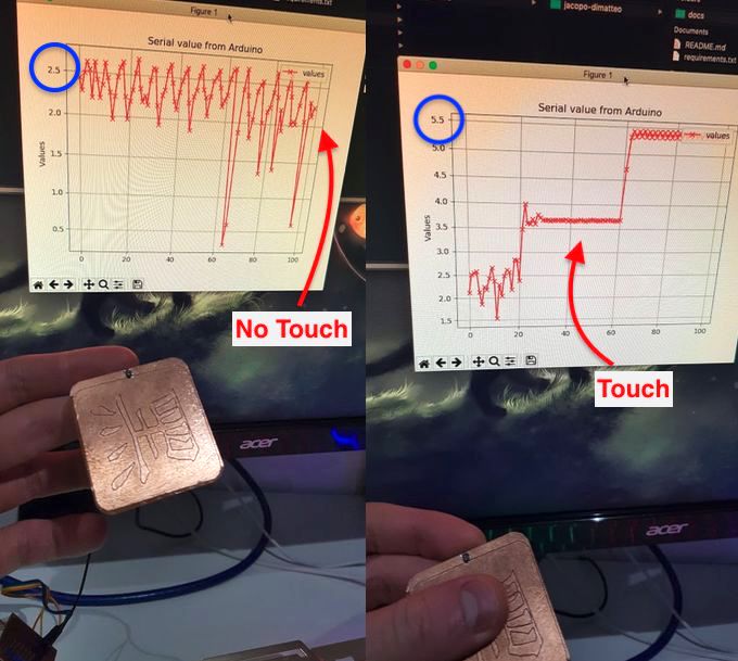
One thing to note about this approach is how SLOW it is, there is 5~10 seconds lag.
We Need to Go Faster - Kivy
Okay, Kivy is a GUI library which is intuitive, and is also fast.
Installing Kivy is straightforward, once again:
python -m pip install kivy
pip install kivy-garden
What we care about with this step sensor, isn’t proximity or pressure, but simply detecting touches. This will be required to identify moves, nothing more, nothing less.
Now that we’ve gather some more information about the output data of the sensor, let’s implement a simple boolean label stating weather the button was pressed or not.
Best place to get started with Kivy:
It’s A Button After All
There are a few changes we need to make to the original code, firstly the imports:
from kivy.clock import Clock
from kivy.app import App
from kivy.uix.label import Label
from kivy.uix.floatlayout import FloatLayout
We should change our if main
if __name__ == '__main__':
    ser_device = setup()
    Gui().run()
    ser_device.close()
In this case, setup() is a modified version of the main() from the pervious version that doesn’t read the bytes but returns the serial device.
Like so:
def setup(device_port=FTDI_PORT):
    # -- Get available ports & connect to Arduino --
    ports = serial_ports()
    device_found = False

    for port in ports:
        if device_port in port:
            device_found = True
            ser_device = establish_connection(port)
            break
        else:
            pass

    if not device_found:
        print("Device not found, PORT name is wrong? Device not connected?")
        exit()
    else:
        print("Connection established")

    ser_device.reset_input_buffer()
    return ser_device
class Gui(App):
    def build(self):
        return Body()
This will returns the body of the GUI, which is described as follows:
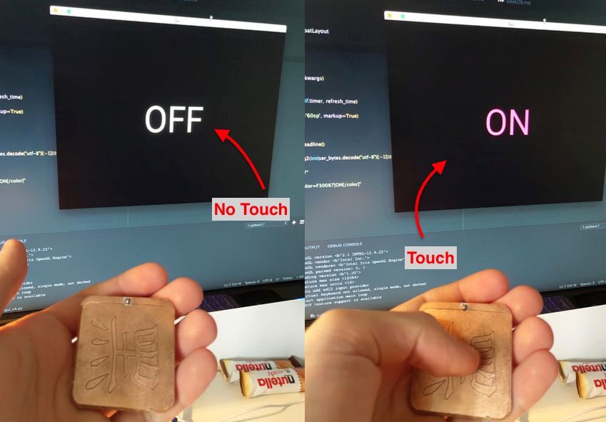
class Body(FloatLayout):
    def __init__(self, **kwargs):
        super(Body, self).__init__(**kwargs)

        refresh_rate = 0.01
        Clock.schedule_interval(self.timer, refresh_rate)

        self.lbl = Label(font_size='60sp', markup=True)
        self.add_widget(self.lbl)

    def timer(self, dt):
        ser_bytes = ser_device.readline()
        try:
            ser_int = int(math.log2(int(ser_bytes.decode("utf-8")[:-1])))
            if ser_int <= 10:
                self.lbl.text = "OFF"
            elif ser_int > 10:
                self.lbl.text = "[color=F30087]ON[/color]"
        except ValueError:
            pass
This is a bit of a mouth-full, let’s break it down a little:
refresh_rate = 0.01
Clock.schedule_interval(self.timer, refresh_rate)
refresh_rate which is in seconds.
If you remember, in the code we uploaded to the board we set delay (50) meaning 50 ms or 0.05 s, so need a refresh rate at around that speed if we want the updates to be live, which is why I set it at 0.01
self.lbl = Label(font_size='60sp', markup=True)
self.add_widget(self.lbl)
Markup = Truelets us add colors to the text.
The timer function should be familiar, the only difference from the pervious version are these:
ser_int = int(math.log2(int(ser_bytes.decode("utf-8")[:-1])))
if ser_int <= 10:
    self.lbl.text = "OFF"
elif ser_int > 10:
    self.lbl.text = "[color=F30087]ON[/color]"
Here we’re doing math.log2 since it gave a nice cut off point at 10 with decent consistency.
Whereas the if elif statement discretize the values, the sensor is read as off when the reading is below 10 and on when it’s above.
"[color=F30087]ON[/color]"are the markup syntax to give the ON button a purple/magenta hue.
This has no detectable lag, and works really nicely. More complex GUI’s could be composed using Kivy fairly easily, but these three examples are enough to cover all (meaningful) representations of the data my sensor can output.
In the end I was happy to have chosen Python for developing the GUI & I believe it’s actually easier, more intuitive and powerful then the Processing alternative, as can be seen with the code above. I highly recommend it.
Download The Files
-> Serial Monitor Code (zipped)
-> Graph Monitor Code (zipped)
-> ON/OFF GUI Code (zipped)