Week 4. Computer Controlled Cutting
4. Computer controlled cutting
Introduction
This week we focus on computer controlled cutting (CCC) using the laser cutter and the vinyl cutter. We will try out and explain the different steps to take from a design to cutting your desing. We first create a sticker with the vinyl cutter, followed by cutting a press fitting parametric design on the laser cutter.
Files
Parametric design file for Fusion360, f3d
Parametric design file for laser cutter, dxf
Laser computer code file
IoT people stickers for vinyl cutter, svg
Hardware
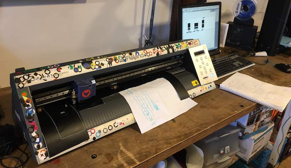
Vinyl cutter - Roland CAMM1 Servo
Laser cutter
Software
Adobe Illustrator (or you can use Inkscape) - for creating the designing for the vinyl cutter
Adobe Illustrator - for cutting our design with the vinyl cutter
Fusion360 - for our parametric design for the laser cutter
Laser Cutter 5.3 - the software supplied for the laser cutter
Vinyl Cutter
We are creating a sticker for our laptop using the vinyl cutter.
We wil be using the Roland CAMM1 Servo.
Software
You can use Adobe Illustrator (or Inkscape) for creating the designing. There is no special software needed for the vinyl cutter, you can directly cut your design from Illustrator using the print dialog.
Creating a design for the vinyl cutter in Illustrator
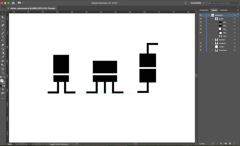
I made a very simple design to cut using the vinyl cutter in Illustrator.
I sketches some IoT compontents that looked like people and recreated them in Illustrator.
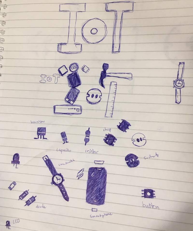
I created them by using the square tool and typing the sizes in mm.
Then I traced the design in the correct size using the vector tool and setting an anchor for each corner. Illustrator than makes lines between each anchor. I filled the shapes with black and made the lines 0.01 points.
I used the measurement tool in illustrator to check if I kept having the correct distances. I really missed parametric design in Illustrator. I even searched for a plugin, but could not find one…
Steps to cut
- Create a design in the size you want to cut.
I rasterized my design and retraced lines to be sure I did not had any overlapping lines or were cutting at the wrong place. - transfer your design to the windows 7 computer that is connected tot the Roland vinyl cutter. Copy your work to the “FabAcademy2019” folder.
- Select your cutting material and place it on a cutting sheet.
- Place your material in the cutter (piece or roll) and put the wheels down.
Rolls go on top of the cutter.
Regardless of size flow your material from the back to the front.
Make sure your material is placed over the light sensors at the front.
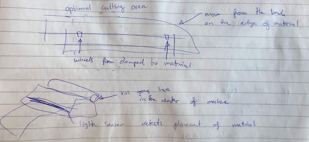
Lift the wheels with the handle to easier flow your material through.
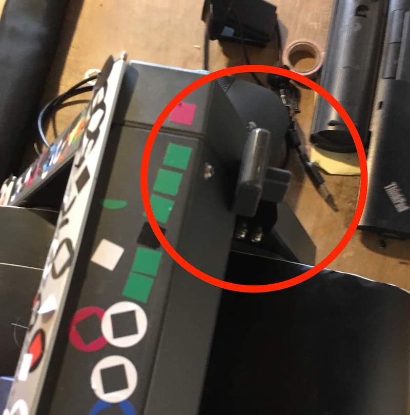
If your material is to small to cover the sensors, use and extra piece of paper, like you can see in this picture.
- Turn the machine on and KEEP YOUR HANDS AWAY FROM THE MACHINE!
The machine will now move and the cutting head can hurd your hand. - Select your material in the menu using the button on the right side of the machine.
Use the buttons to properly place our material. - Next we will handle the cut: force (how hard), speed (how fast) and dept (how deep the knife is in the material)
- Remove the knife from the head, clean it and check its status and if the height/dept is set correct.
- Place the knife back and place the header with the set “origin” option in the menu.
- Set speed to 10cm/s
You can find the speed in “menu”->condition->”enter” - Set force to 100 (for normal material, if you use different materials this force might be different)
- Press the “test”, Remove the vinyl with the vinyl-tweezer and see if the square and circle are cut the correct size and depth.
- Set your origin for your next cut, before every cut set your origin
- Open your file in Adobe Illustrator,
check if your file is the size of your cut,
check if your line thickness is 0.01 points (Normally the vinyl cutter will cut on the outside of your line, if the line is thicker than 0.01 points the vinyl cutter will cut on both sides of the lines) - Select File->print
Set placement position to 0,0 top or bottom corner
Goto “Setup-“ then “Roland” and select “Preferences” -> “get from machine”
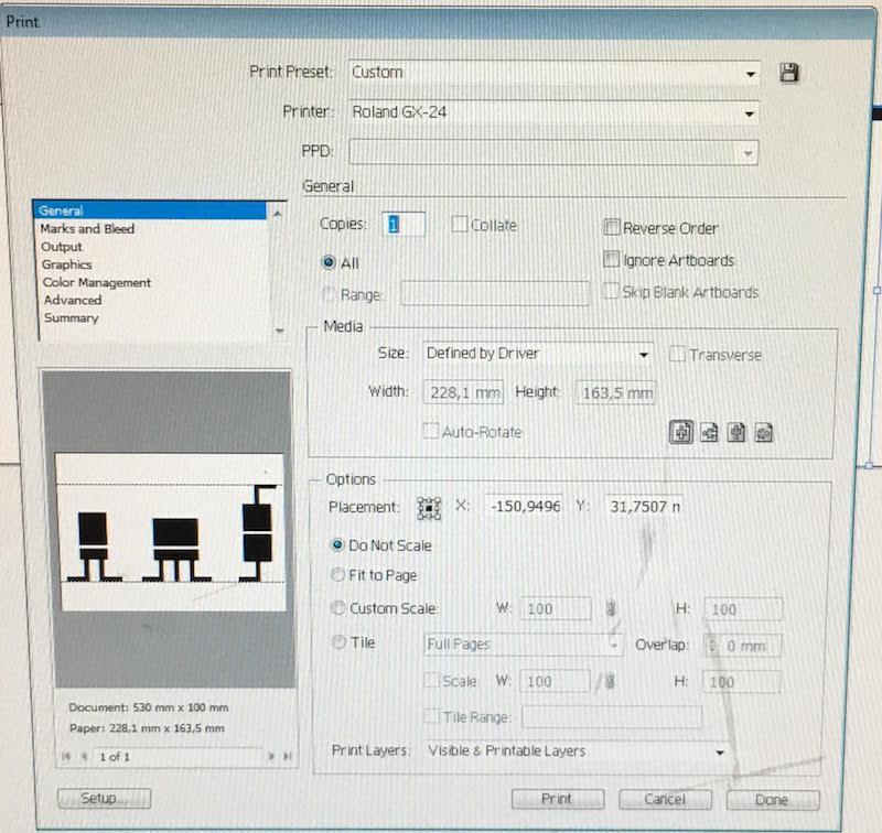
- Press “print” to start cutting
- Stay at the machine will cutting, sometimes you need to feed the material through.
Remember! Do not stick your hand in the machine! - After cutting clean op your material.
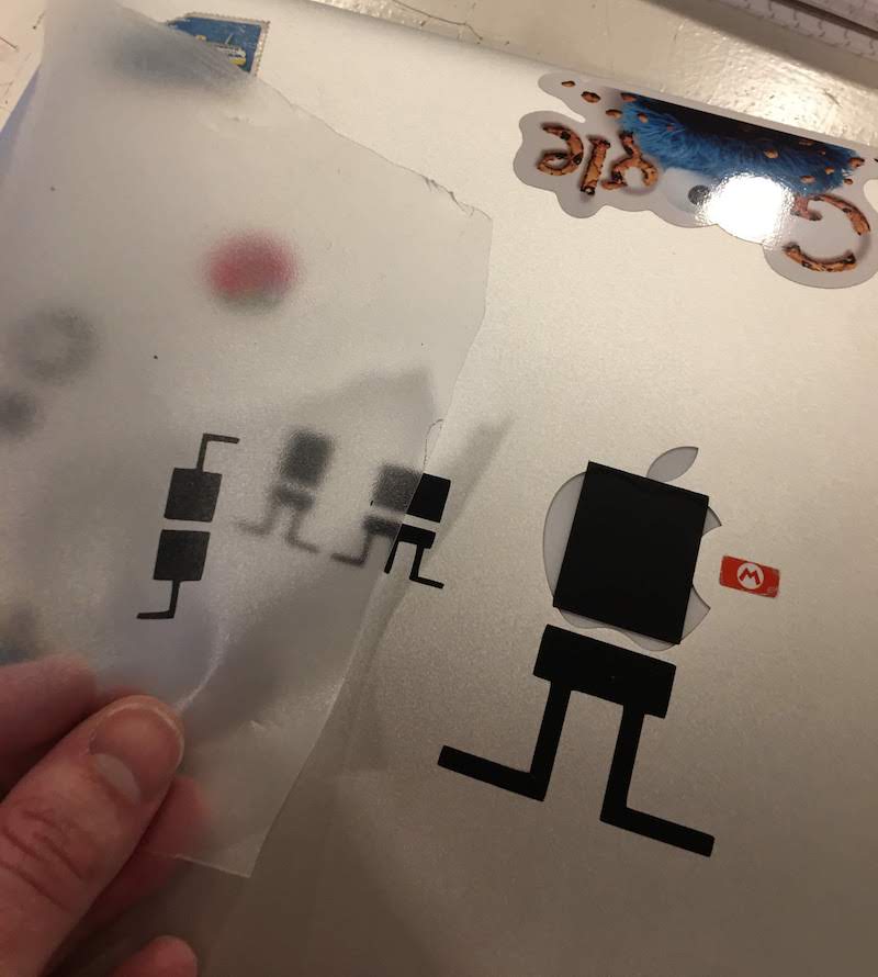
Transfering a sticker cutout
If you made a sticker cutout of one or multiple colors, you can transfer them with transfer paper.
- Make sure your material is clean and the cut it through
- Cut a piece of transfer paper and place it on your cutout
- Firmly apply the transfer paper, there is a special rubber pallet you can use.
-
Gently peel of your transfer paper, check to see if your cutout moves with the transfer paper, you can use your tweezers to help.
Note: If you are like me, and had no succes with the transfer paper, you can also peel of your cutout and place it on the transfer paper.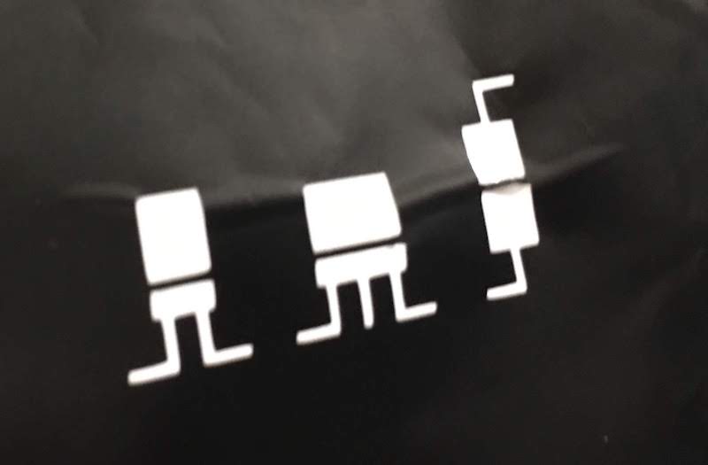
- Next apply the transfer paper with the cutout on the surface you want to stick it to. (in my case my laptop)
Laser Cutter
The following explaination is made for the laser cutter at the Waag Society in Amsterdam. This is a laser cutter: ….
Sofware
The software we use is Fusion360 Next we use Laser Cutter 5.3, the software supplied for the laser cutter.
Before you start
- You are working with toxic materials be carefull and always make sure there is proper ventilation.
- NO long hair, long sleeves or lose ropes ect! You do not want to get stuck in the laser cutter while it is cutting!
- Know what to do in case of FIRE!
- Check if your material can be cut using the laser cutter. Materials that are ‘safe’ to cut are: plywood and solid wood, cardboard with 1 air pocket, paper, acrylic, and naturally/vegetable died textiles. Materials that are not safe to cut are: cardboard with multi-air pockets, PVC and undefined plastics, croline holding materials as textiles and vinyl. If you do not know the precise contents of your material you are not allowed to cut it.
- When the laser cutter is on you never leave the device and monitor your cut. (if you don’t monitor the cutter you might break the laser cutter or cause a fire)
- Wen you are finished with your cut always wait a few minutes for all the fumes to be sucked away.
- If you do not know what you are doing, ask somebody to help.
What to do in case of FIRE!
The laser cutter burns material away, this burning can sometimes be to hot for the material.
For example you can cut to slow with a to high temperature, or you are using material that is not fit to cut using a laser cutter (like multi-layered cardboard).
So you might cause fire in the future, if this happends these are the steps you should take:
- Shout fire! You surrounding should know that there is a fire, in case the fire is escalating.
- Press the big red STOP button on the laser cutter. This stops the laser.
- Turn off the fan. This will reduce the oxigen inflow.
- Take the water bottle.
- Open the laser cutter and put out the fire with water.
- Before you restart with cutting,
turn back on the fan or open a window, wait a few minutes untill the smoke is gone,
check what went wrong, clean and dry the laser cutter and fix what went wrong.
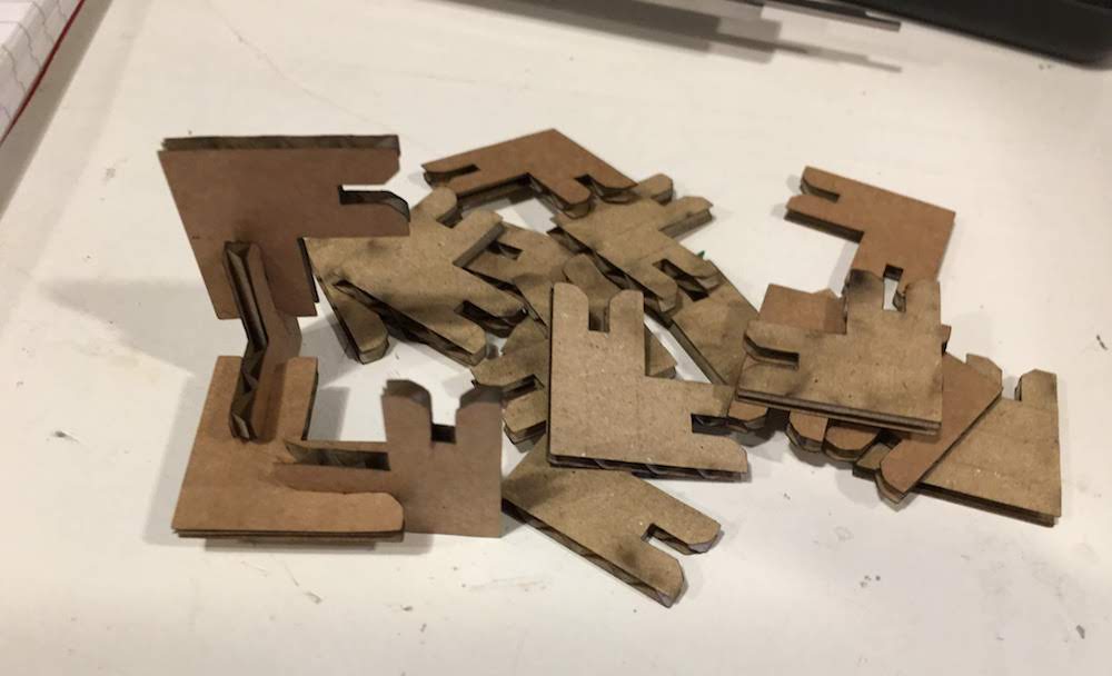
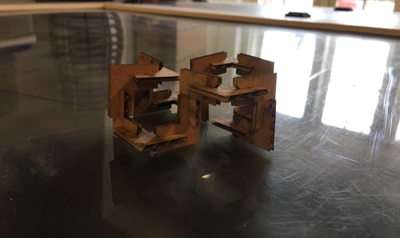
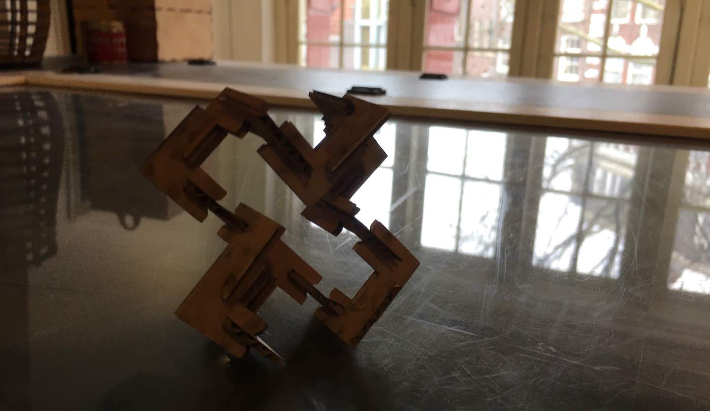
Creating a press fit design with cardboard
We are creating a press fit design using carboard.
We will be using Fusion360 and parametric design, meaning that all distances are defined in paramaters. We can edit this during and after our desing, to get the correct fit for our press fit design. Notice the comments, they can really help explain to yourself what you are doing.
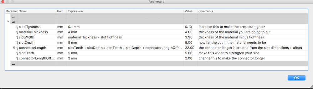
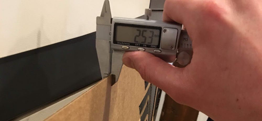
Presscut design uses joints, for this you need to know the thickness of your material.
There are different joints optimal for different materials.
We are using cardboard so the joint needs to be sturdy but simple.
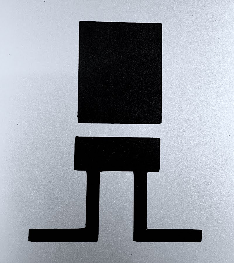
We use a simple slot design, with around the edges a slope to easily allow the material to slot in the cutout. Notice in the image we determine a different parameter for each part of the design.
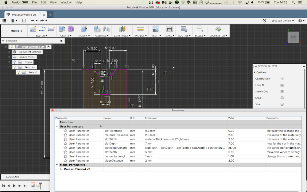
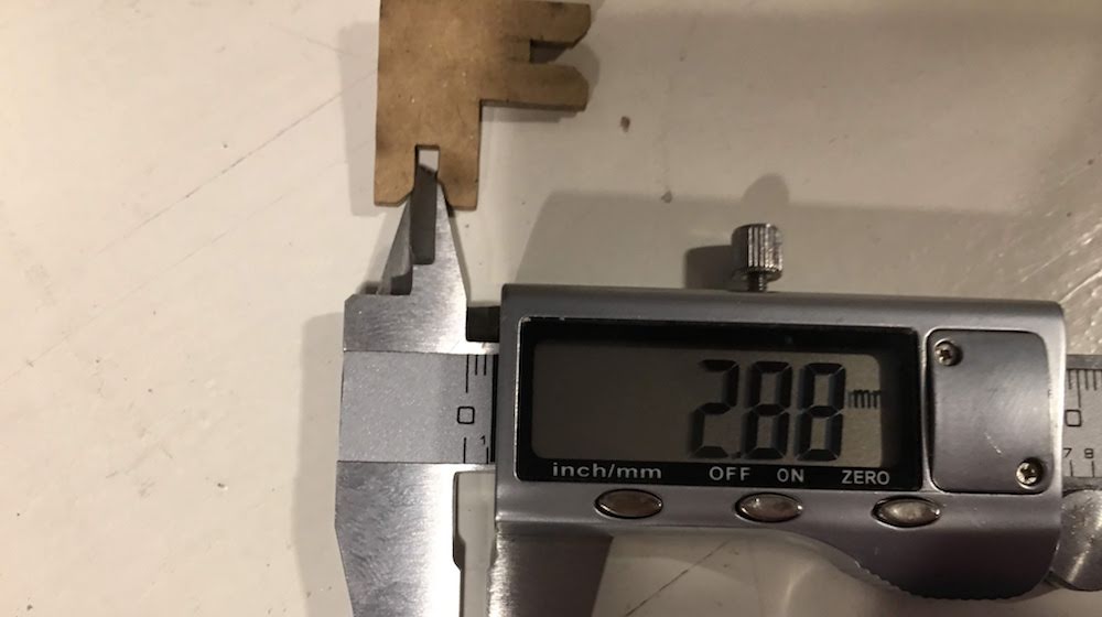
Last is the offset. The offset is half of the kerf of our laser.
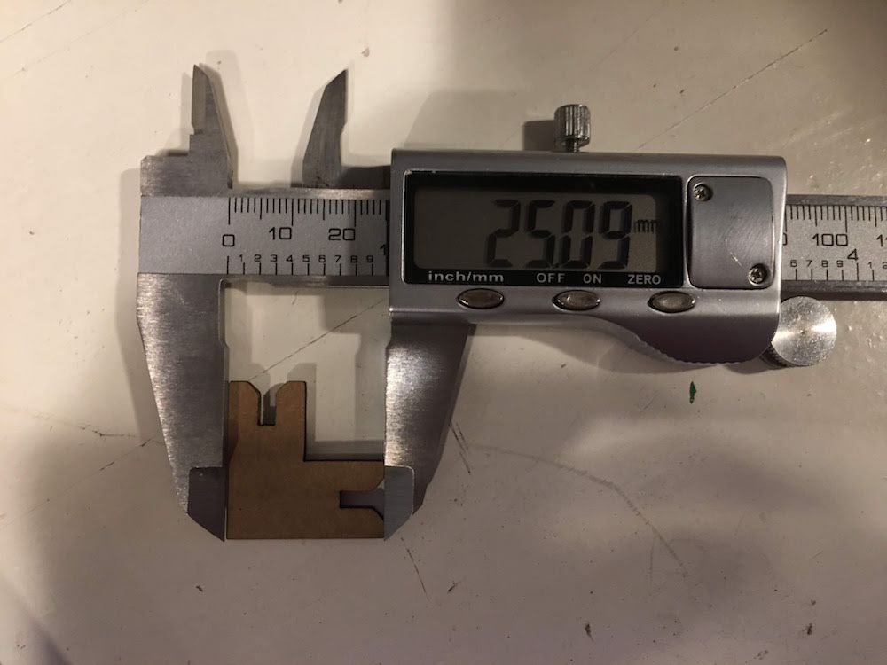
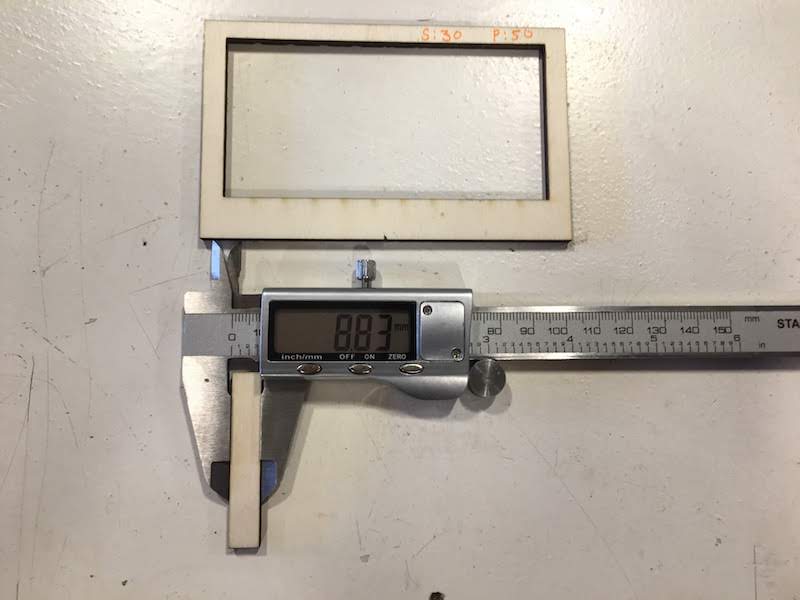
To determine the offset I looked up the offset for lasercutter as determined by Heidy and Anne for our cardboard material and our laser. I made a testcut of my design and measured how much the design was off to determine my offset. If you can not make a testcut at this point, just finish your design and go through the next steps. You can always go back to your parameteric design and update it later.
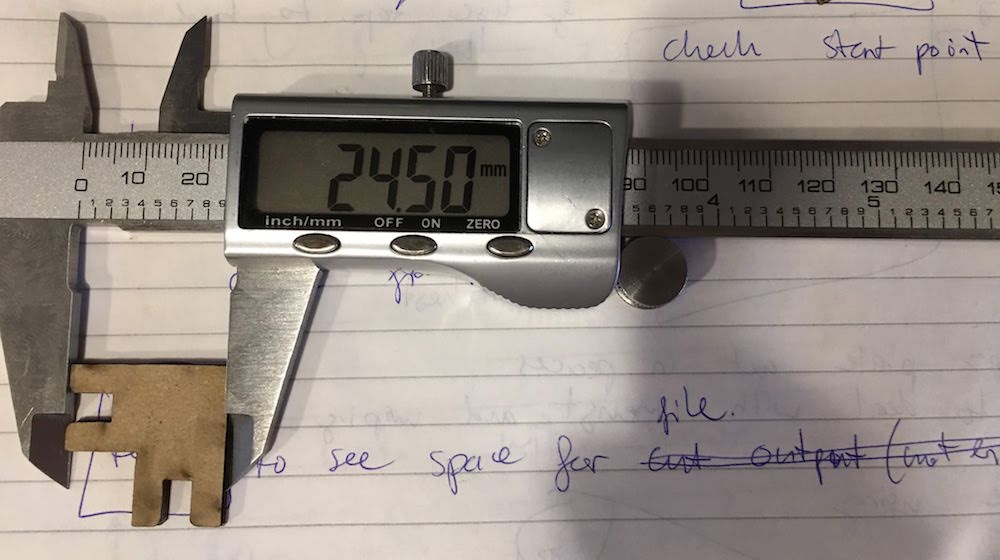
I went through three itterations before I had determined the correct offset. In this case for 3.74 mm cardboard the offset is 0.15 mm.
I defined this in my parametric design as slottightness of 0.3 mm (2 times 0.15mm).
Having made our design we can go onto cutting.
From design to the laser cutter
- Create a 2D vector design in your favorite tool. We used Fusion360.
- Make your design in the size that you want to cut, but keep it in mm.
- Check if you have overlapping lines or double lines. Remove these double lines, a double line will result in the laser passing the same spot twice. Most of the times you do not want this, since it will burn away more material than you intent.
- If your design asks for different types of cuts you can give each peace with a different cut a different color. You do not have to do this know, you can also apply the colors in the laser cutter software.
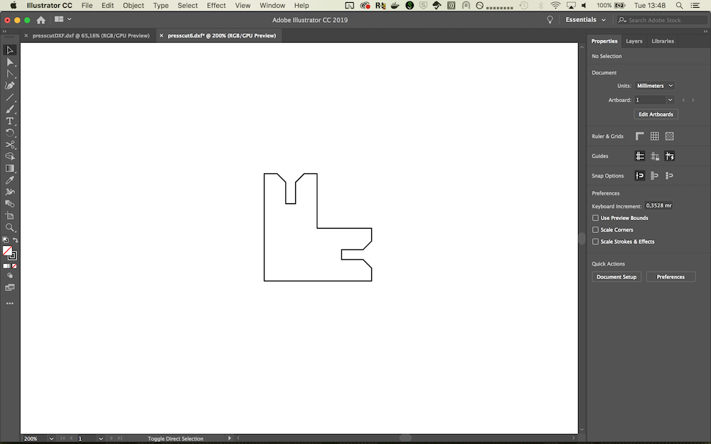
- Export your design to either CS2 (if you used colors) or DXF format (if you did not used colors). Unfortunately the laser cutter software does not support otherfile formats. We exported our desing to dxf in Fusioon360.
- Copy your design on a USB stick.
- Place the USB stick in the laser cutter computer.
- Open the Fabfiles folder and create a new folder with your name
- Copy your design to this folder.
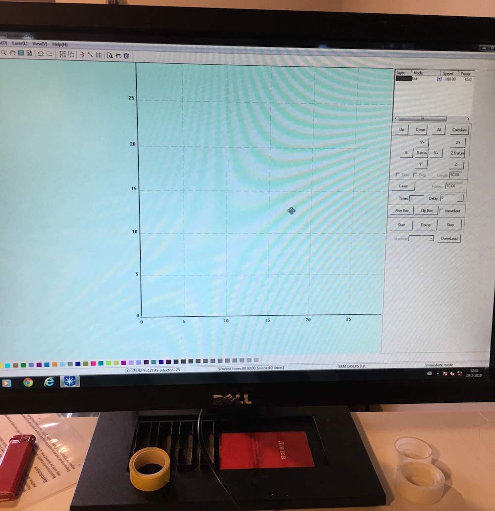
Setting design in laser cutter software
- Open de cutting software on the laser cutter.
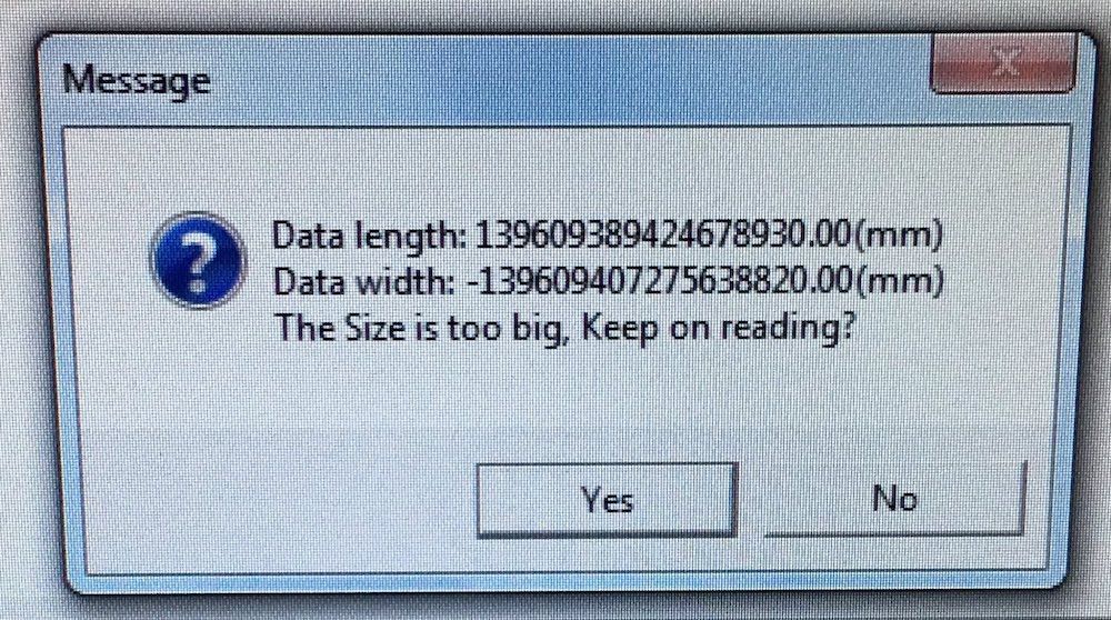
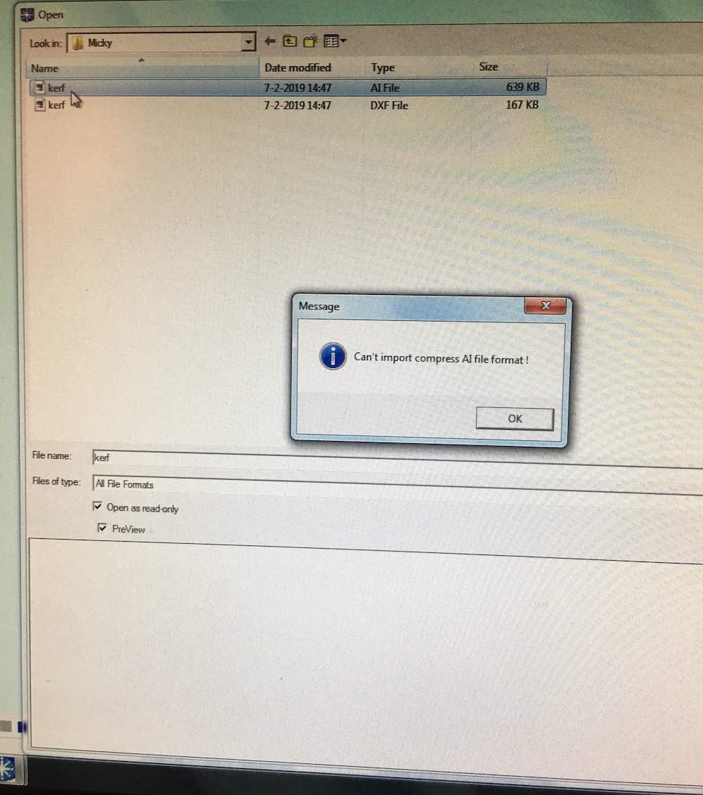
- Import your design using the import feature. ( CTRL + i for the power users). Note that when you select a file to import and you do not receive a preview, the software most likely will crash. This can either be a result of using an incompatible format (only CS2 and DXF are supported) or a corrupt file.
If you are sure you have a compatible file, but the software keeps crashing on import, recheck your work in Illustrator and reexport your design.
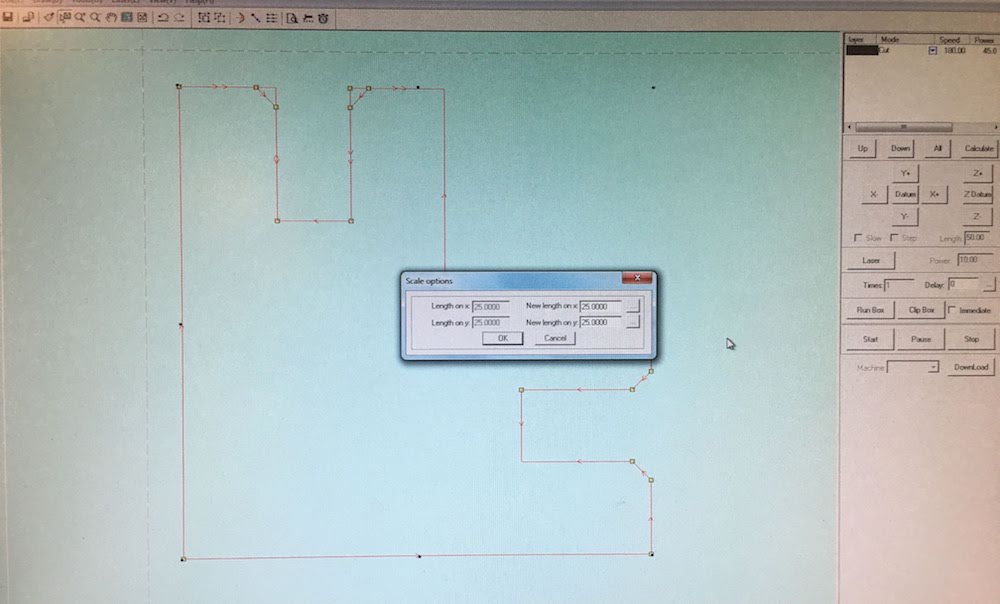
- When you successfully imported your file, the software changed the scale of your design. Select your design and check the scale using the scale option.
Adjust the scale on one axis and then select the dotted button on the other axis to allow the software to calculate the scale for the other axis.
- Having your desing in the proper scale, check if your lines are united. Use the united lines option of the lines are not united.
- If your design asks for different types of cuts, give each part with a different cut a different color. If you colored your lines in Illustrator, check if the colors are still correct.
- Assign the proper cut values (speed and power) to each color.
In my case I used:
Speed: 80
Power: 50 - Next orden the different parts where the top is the first, and the bottom is the last
- Set the starting position of your cut using the set achor option.
The starting point is the blue dot on the screen. But you use the red dot button.
The advice is to use the topleft for your cut, this is the easiest with this laser. - Save your file, use a distinct and short name
From software to cutting
- Having our desing preset in the sofware, we can not get on to the cutting.
First place your material.
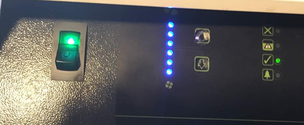
If you use cardboard like me, make sure to use some tap to keep it attached to the surface. - Close the laser cover, turn on the laser and the ventilator using the proper steps 1,2,3.
Make sure the ventilator is at maximum strength.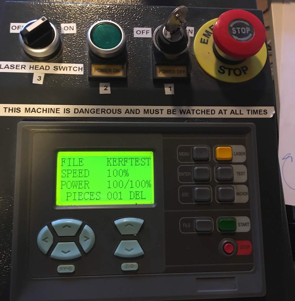
- First we will calibrate the laser. Place your calibration wood on the center of yuor material and move the laser above the wood.
You can use the arrows at the right side of the panel. - Unscrew the laser gently and move the nozle towards the wood and tighten the laser. The laser should be fit to the material with a tiny pressure, but you should be able to move the wood.
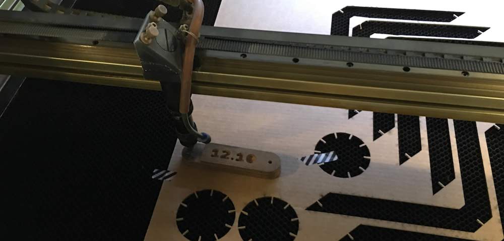
- Now use the arrows to move the laser to your starting poistion.
Go to the menu and select “anchor”-> set origin and “enter” - Go back to the software.
Select the “To cut” button. Next select “Delete all”, then “download”. This sends the file to the laser cutter.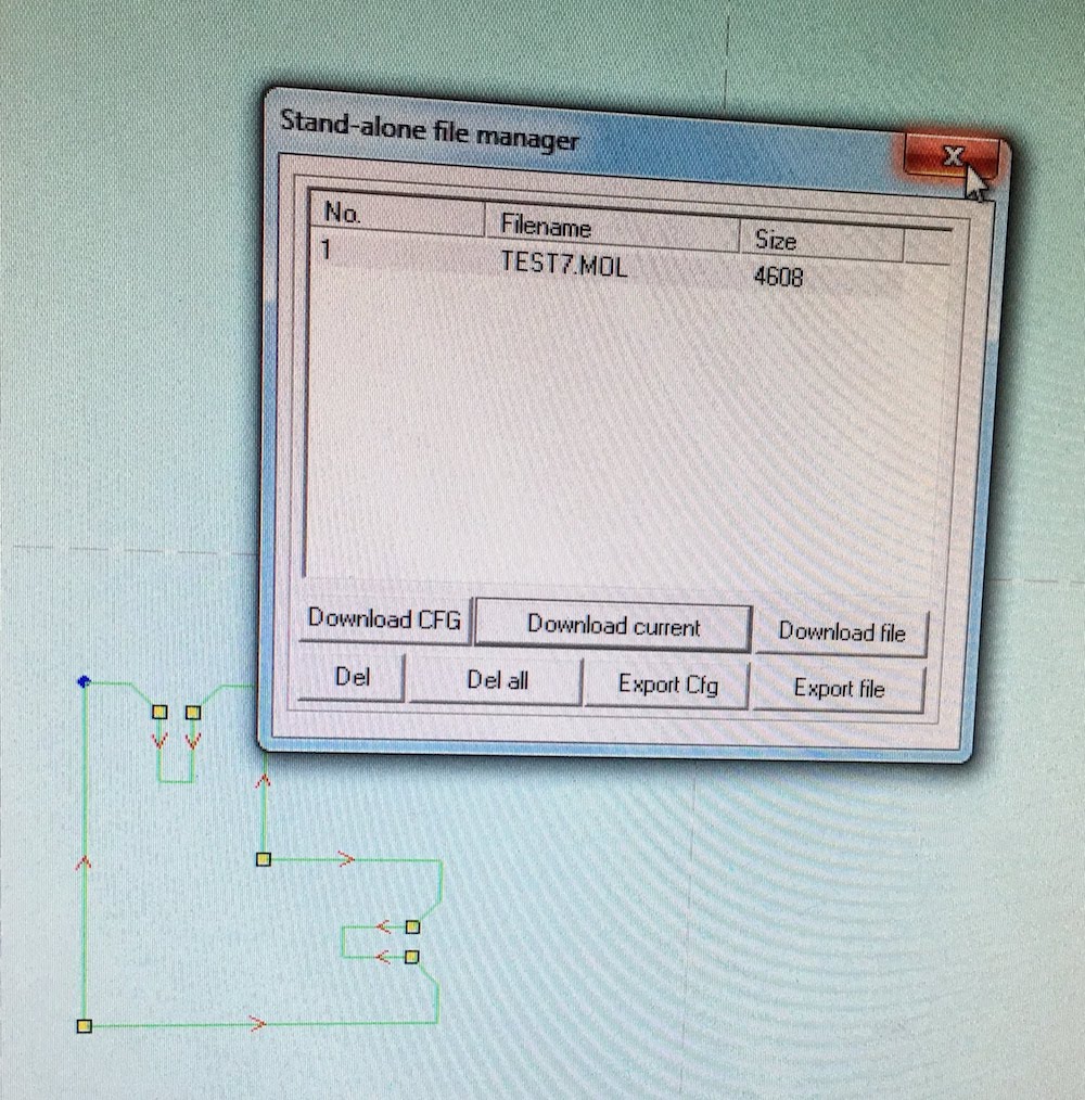
- Go back to the laser and load the file using the “file” button. Check if the file name is the same as the file you send.
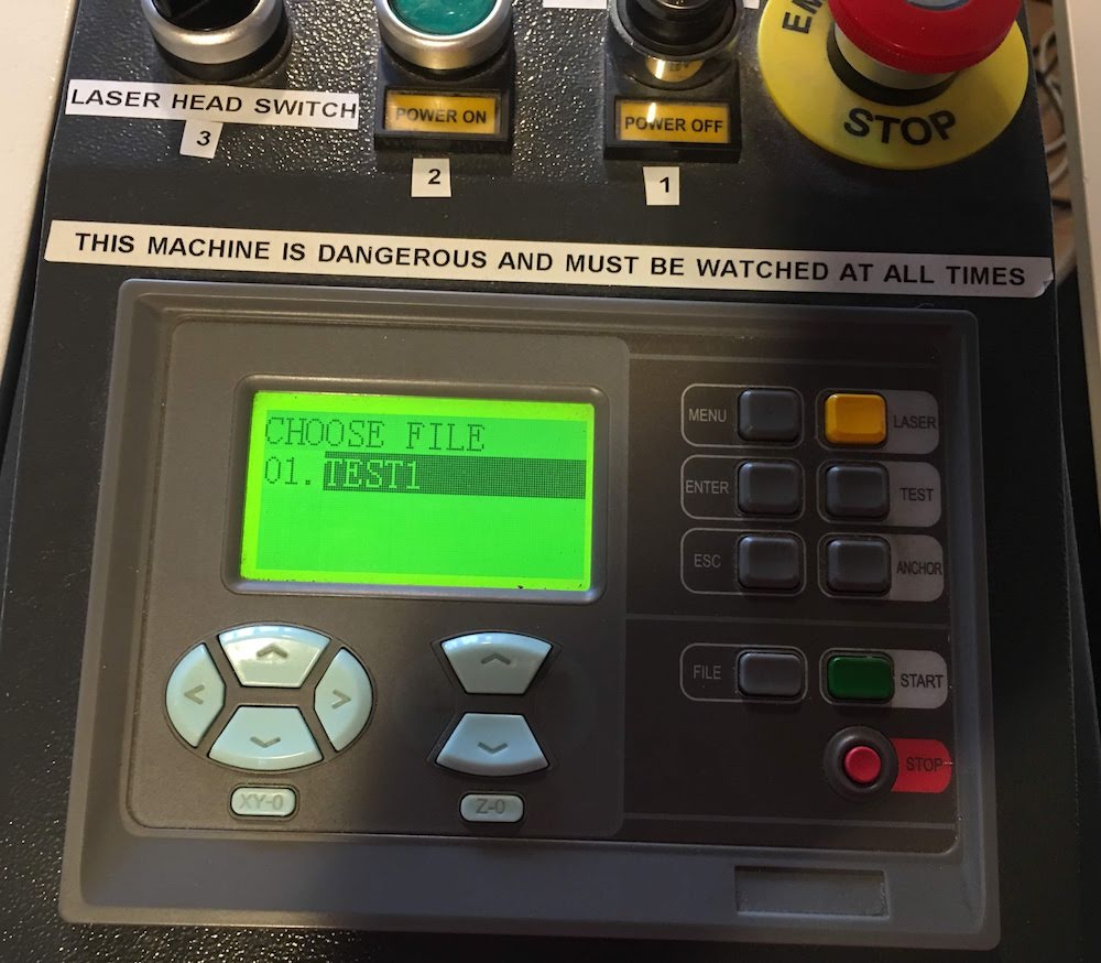
- Test your cutout using the “Test” button
- If everything checks out, you can start cutting.
Press “start”
Sometimes the laser will pauze, you can resume by pressing start again.
If you want to stop the laser while cutting press “stop”
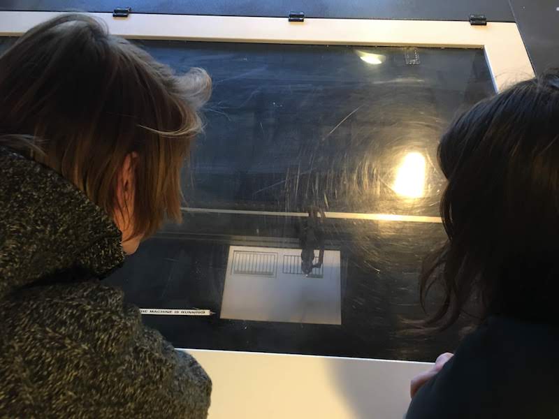
- While running keep an eye on th elaser and your material, YOU DO NOT LEAVE THE LASER.
- When the laser is finished it beeps and moves to the starting position.
Wait a few minutes for the fumes to be sucked away,
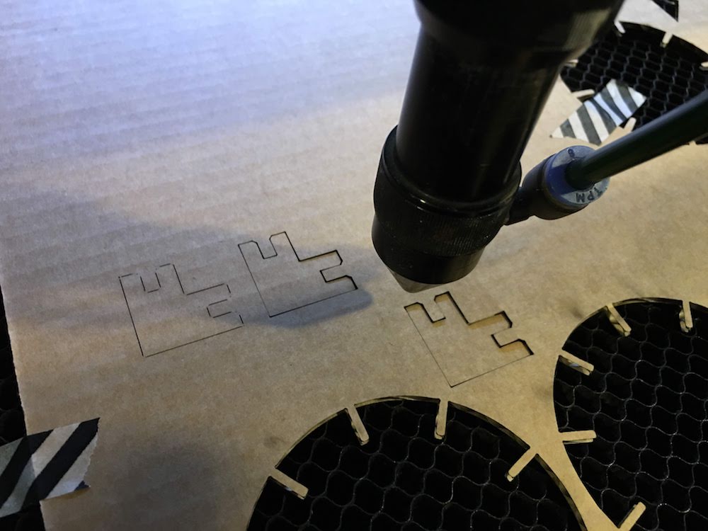
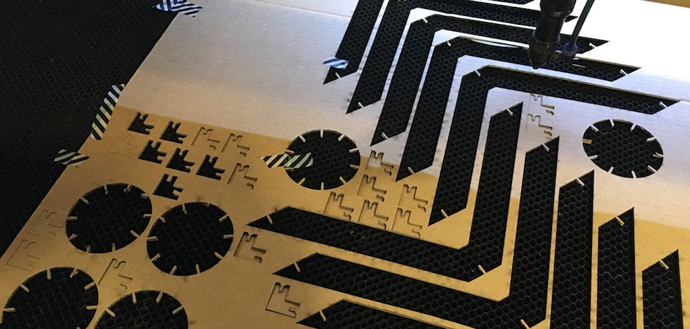
then remove yourmaterial and waste. - If you want to make more cuts from the same design. You can set a new staring position (anchor) and press the “start” button again. If you do this multiple times, you get something like this.
- When you are finished shut down the laser, fan and computer.
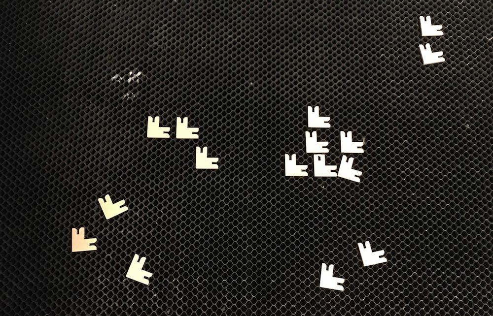
- Now comes the fun part, we made multiple cutouts and can now assemble them to make something pretty.
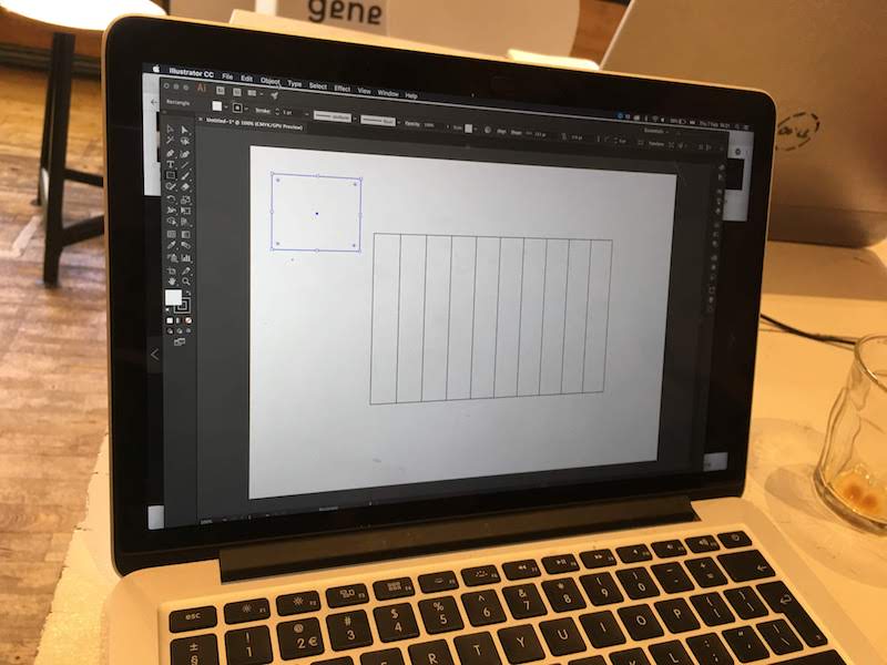
Offsetting the laser for the kerf
For our group assignment we had to determine the kerf of the laser.
This means we have to find how much the laser burns away.
If you want to make precise cuts, as with a press fit design, you need to know the kerf and take this with your design.
Although the laser burns away only a small part, like 0.1 mm of the material, this is enough to change your designed dimensions, and can result in pieces not fitting perfectly.
How to determine the kerf:
- Create a design that allows you to measure the kerf multiple times.
We used Illustrator to create 11 pieces of exactly 100 mm in total, thus 100 / 11 = 9,09 mm.
When cutting those pieces and measuring how much mm is substracted from the 100 mm, we can divide this difference by the amount of kerf lines, 11 in this case (10 full cut lines, and 2 halfs at the sides = 11).
Also we can measure each individual piece and compare the difference between the pieces.
- After designing a kerf test, export it from illustrator to a file your lasercutter software accepts, we used DXF.
Copy the file to your lasercutter and import.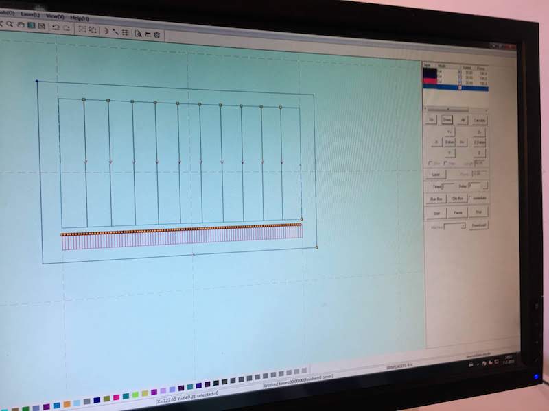
- Select the lines you want to cut, we tested on plywood and used 4 different cut settings. We used different settings to see if there is a difference between applied speed and power of the laser.
Also make sure to make separate cut profiles for the vertical lines and the horizontal lines. We first cut the vertical lines and for last the horizontal lines. This allowed the wood to stay connected for the longest time, ensuring a more accurate cut.
Test 1: Speed: 30, Power: 100
Test 2: Speed: 30, Power: 50
Test 3: Speed: 15, Power: 100
Test 4: Speed: 15, Power: 50
.
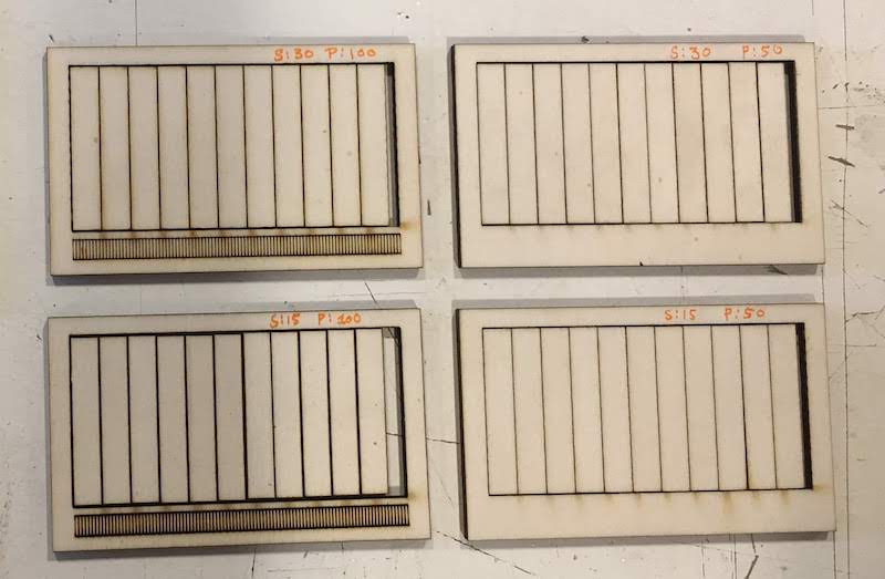
- After cutting we took individual pieces and measured the difference.
We got the following results of the total:
Test 1: 100 - 97,25 = 2,75 / 11 = 0.25mm
Test 2: 100 - 96,96 = 3,04 / 11 = 0.27mm
Test 3: 100 - 95,03 = 4,97 / 11 = 0.45mm
Test 4: 100 - 97,52 = 2,48 / 11 = 0.23mm
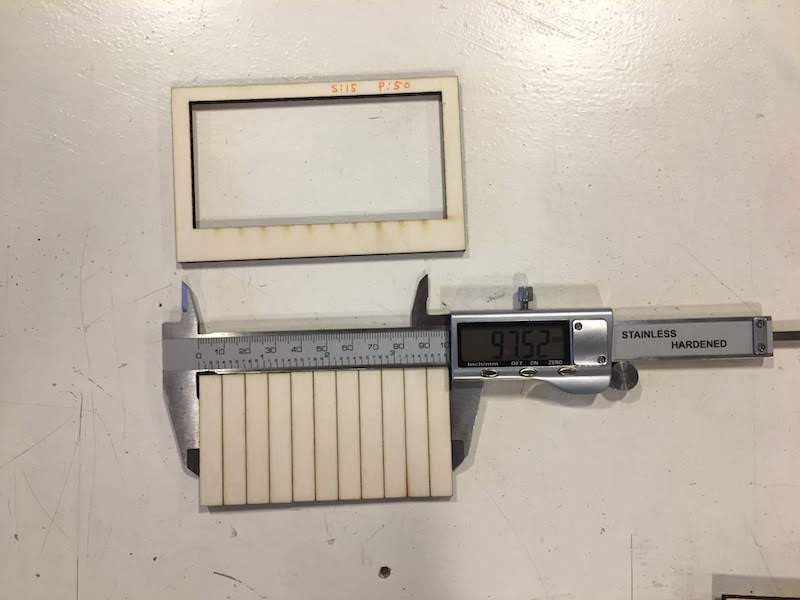
We also measured individual pieces and got the following results:
Test 1: 9,09 - 8,58 = 0,51 mm
Test 2: 9,09 - 8,82 = 0.27 mm
Test 3: 9,09 - 8,66 = 0,43 mm
Test 4: 9,09 - 8,72 = 0,36 mm
Comparing the combined and the individual measurements, we see a big difference.
This can be due to measurement errors mostly.
The combined measurement was really difficult because it is almost impossible to keep 11 pieces fitted together. The individual measurement was difficult, since it is only one piece.
Comparing all the different cuts and measurements we see our kerf is around the 0.25mm. - To determine the offset for our design we now take our kerf and devide it by 2. Our offset is after all only one part of the kerf line, not the whole kerf line.
Final project - Creating a leather arm band
After discussing with Micky, I really wanted to create my own leather arm band.
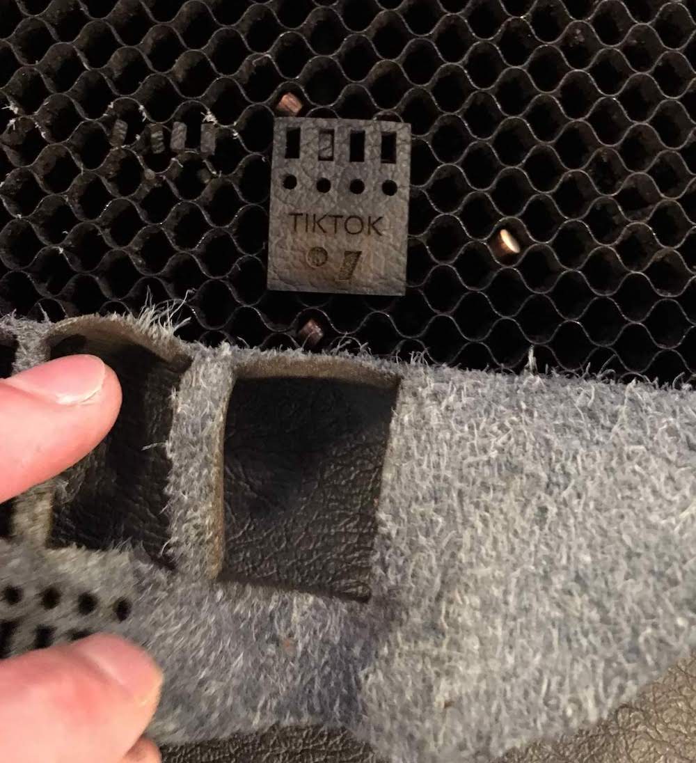
I experimented with two small pieces of leather (thank you Micky) to create the TIKTOK arm band strap.
In Adobe Illustrator I designed the armband.
Looking at similar bands, I decided my dimensions.
Dimensions:
- lenght: 420 mm
- width: 22 mm
- holes length: 120 mm
- holes diameter/width: 2.2 mm
I created a rectangle of 420 by 22 mm, and modified the top corner with the Direct Selection tool (white pointer) to give it a round finish.
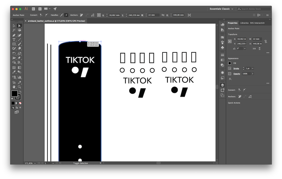
Next I drew some circles at one side for the holes for the pin of the arm band.
And I created a small rectangle at the other side of the rectangle for the position of the pin.
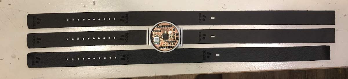
Last I though it would be nice to decorate the band with engravings of the TIKTOK logo, so I places a few logo’s on it.
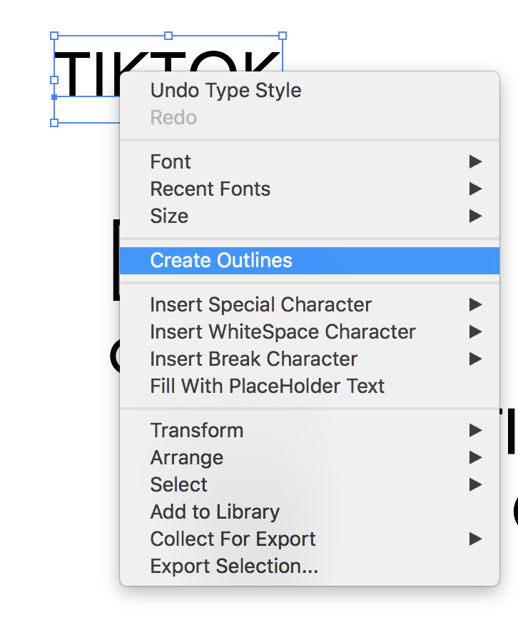
Note that when you want to laser cut text, you should first make vectors out of the text.
This also saves you hasle with transfering the design to another computer that does not have the font you use.
You can create a vector out of you text by right clicking your text and selecting the option, create outlines.
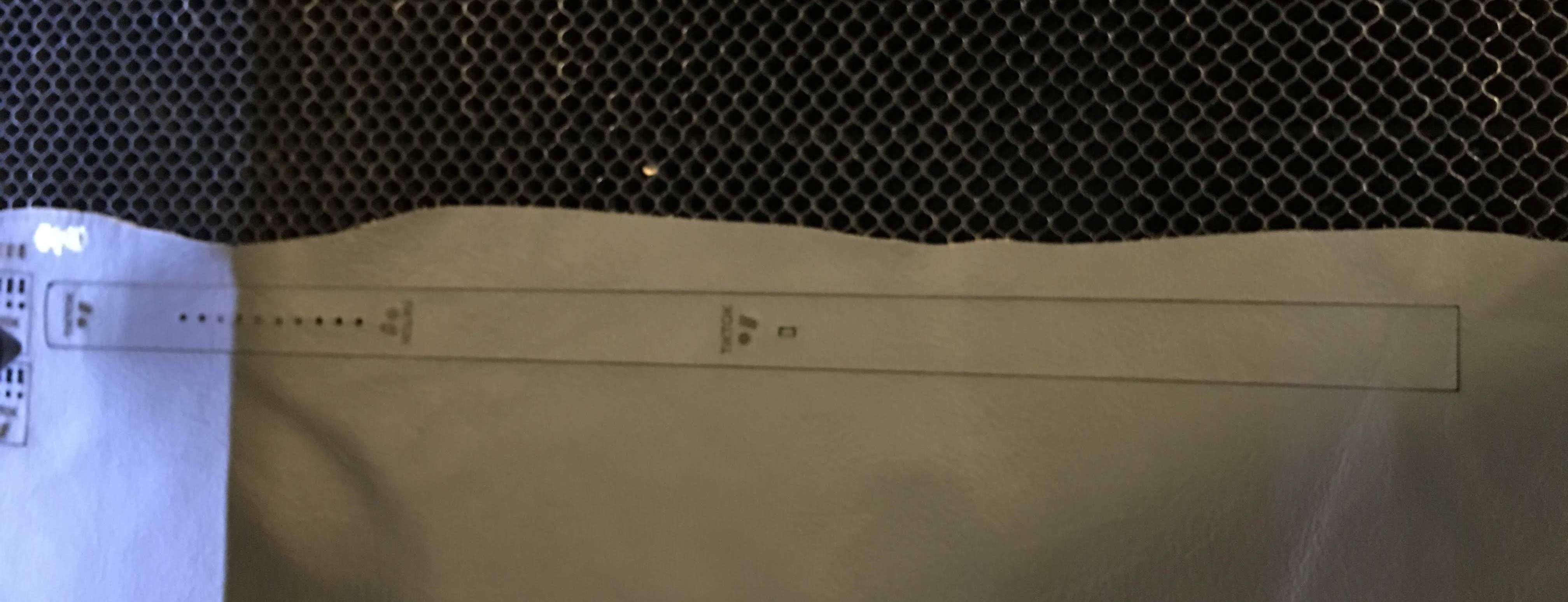
Next to the band, I created two small test designs, as you can also see in the picture.
I saved the Illustrator file as .ai and .dxf and copied them to the laser computer.
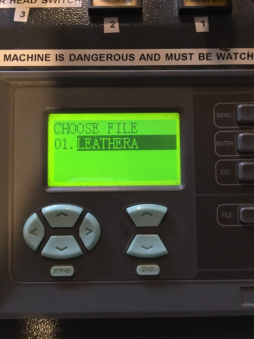
I took my laser manual I made in week 4 and started the laser software, and imported my design.
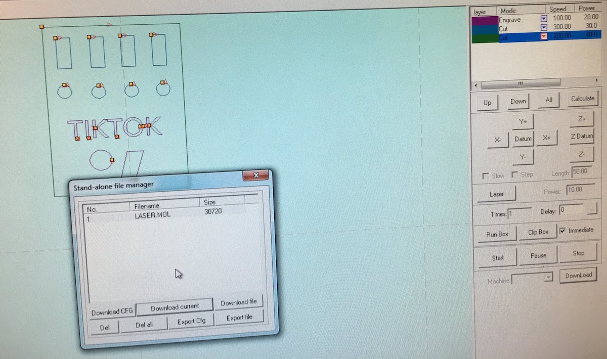
I selected the test cut piece and gave each item a color, and assigned to each color different settings.
Since I had not cut with leather before, I did not know the correct laser speed and power combination.
I had 5 circles, and for each one I selected a different cutting setting.
For example I started with:
- speed: 500, power: 10
- speed: 400, power: 10
- speed: 300, power: 10
- speed: 200, power: 10
- speed: 100, power: 10
I worked my way up to a higher power, and ended up selecting the cutting for speed: 300 and power 30.
Next I tried engraving with the same systematic approach, using the circles as a start.
After finding a nice engraved circle I tried to engrave the TIKTOK logo on the test piece.
I ended up selecting for the engraving:
- speed: 100, power: 20
Higher powers looked to burned for my tast, and higher speeds actually spoiled some engraving outside the desired area.
Last I tried the cutout settings around my engraving to cutout the test piece.
I found that my previous selected power and speed combination did cut through the material, but left some thin lines of fabric connected, giving a rough uneven look when releasing the piece from the leather.
After some trying with larger speeds, I concluded I had to use: - speed: 80, power: 50
I think this big difference between a larger square and a small circle has to do with the laser slowing down when reachting a corner, and needing a certain lenght to get up to speed. The circle was simply to small for the laser to actually reach the speed 300, but with the bigger square I was able to reach this speed.
After finding the correct settings, which took me 1,5 hours I had to try on my actual design.
And… Succes! While I only needed one, I made 3 pieces to have some spares.
Time management.
I find this task a really nice example of my planning and triage, I had to keep my design simple to finish in time and almost finished exactly at the desired time. The leather band is a nice addition, but should take me to much time. Therefor I allowed me to take 5 hours to make the band.
- 2 hours design
- 2 hours cutting
- 1 hour finishing Also I would save this activity for the final days, since, if I could not find the time, I would make a sticker on the vynil cutter.
Thirsday I had to make my band on the laser cutter.
From 13:00 the device was reserved, so I had to finish it before that time.
I decided to take the time from 9.30 till 11.00 to design the band and test cuts in Illustrator,
and cut from 11:00 till 13:00 different band versions.
I finished my cut at 13.15.
Fails
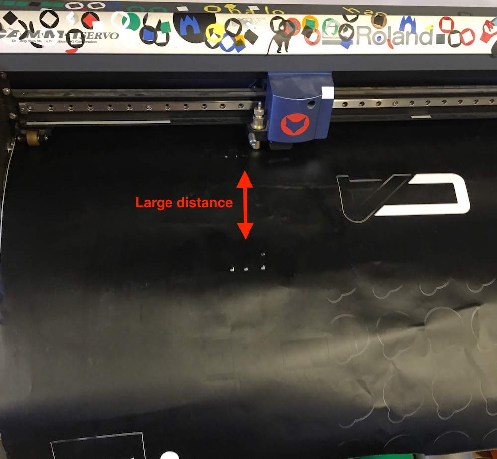
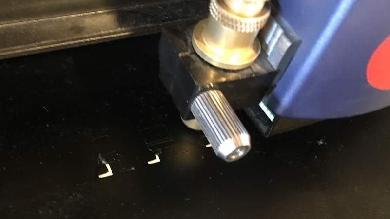
Forgot to set origin inbetween vinyl cuts.
After my test cut I started cutting my own design. I noticed the vinyl cutter was cutting at a different position than I had set.
I kept having issues with this, and could not understand what happened. I check the print settings and the print size.
Only days after my cutout, I realized I forgot to set the origin inbetween my cutouts as I had written in my documentation.
Curling cutout and wobly lines on vynil cutter
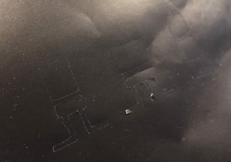
My initial idea was to make many small IoT people. This turned out to be to small for the knife I used. The knife was apperently at the end of its life and was not cutting as it should be. This resulted in the knife not only cutting, but also peeling of the sticker.
I solved this problem by making my cutout larger, 3x and 10x my initial size.
This worked, but since the knife was end-of-life, I also had wobly lines intead of nice straight lines.
Press fit errors in designing using Fusion360
-
I did not set my parameter for the short leg of the connector correctly set. made it first half the connector lenght, should be the width of the cut with its teeth. Found out by mirroring my design and the mirror line was not 45 degrees. A simetrical shape in this case should have a 45 degrees angle. When creating a 45 degrees mirror line you see the error as an overlap.
-
Adding the slope to the cut was difficult without removing the set contraints. When adding the slope I had too many lines, but removing the old lines also removed the constraints. I solved this by transforming the old lines into guides and drawing new lines that were missing. Testing by adapting the slope offset, and it worked, the whole system rescaled.
-
Forgot to add slot depth to second slot tooth. This again resulted in an asymetric broken design. By adding the slot depth to the second tooth evyerthing realigned again.
Measurement errors
As can be seen in the group assignment, we had many measurements errors giving all kind of different end results for our kerf.
We solved this by measuring multiple times and at multiple places.
To show how difficult it is to measure accurate and the big difference I kept our initial measurements in the description.
Mainy exporting fails with Fusion360
I made my desing for the lasercutter in Fusion360.
I exported it to DXF, but this sometimes gave errors when importing in the laser cutter sotware. Or I would get only a small dot and would not be able to fix the size, or I would get errors that my file is to big.
It was only sometimes, the first two times I did not had problems. But the 5 exports after that I did.
Eventually I fixed the problems by loading my desing in Illustrator and exporting it from illustrator.