Week 12. Output Devices
12. Output devices
Assignments
Group assignment: “Measure the power consumption of an output device”
Individual assignment: “Add an output device to a microcontroller board you’ve designed and program it to do something”
Software
KiCad (Design software for schematics and PCB-design)
Arduino (IDE to write code for the ATTiny)
AVR-Dude (software that allows us to talk to the ATTiny board via the USBTiny)
Hardware
USBTiny
Roland Modella MDX-20 mill
with the mill bit for traces - mini end mills two flutes 0.40 mm 826 (damen.cc)
with the mill bit for cutout - two flutes 0.8 mm
Multimeter
Knife
Anti static tweezers for electrical components
Solder iron
Solder tin
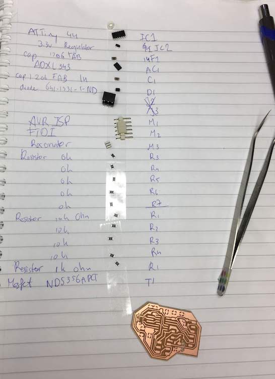
Various surface mounted components (ATTiny 44, ect)
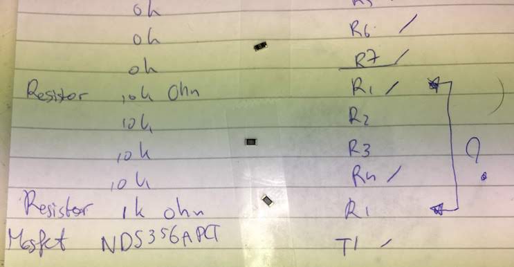
Components for vibration motor circuit: vibration motor, 1µF capacitor, diode 50V 1A, MOSFET 100V 1A, resistor 1kOhm, resistor 10kOhm
Files
KiCad schematic and PCB Design
Improved KiCad schematic and PCB Design after noticing errors
Traces image for mill
Holes image for mill
Cutout image for mill
Code for Group assingment LED blink
Code for simple High/Low switch
Code for PWM test with vibration motor
Code for vibration pattern tests
Group Assignment
Group assignment: “Measure the power consumption of an output device”
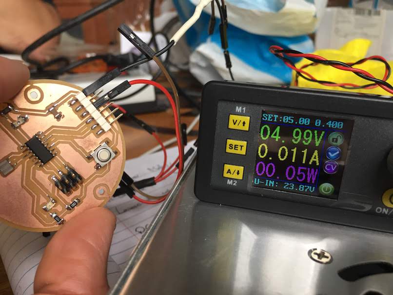
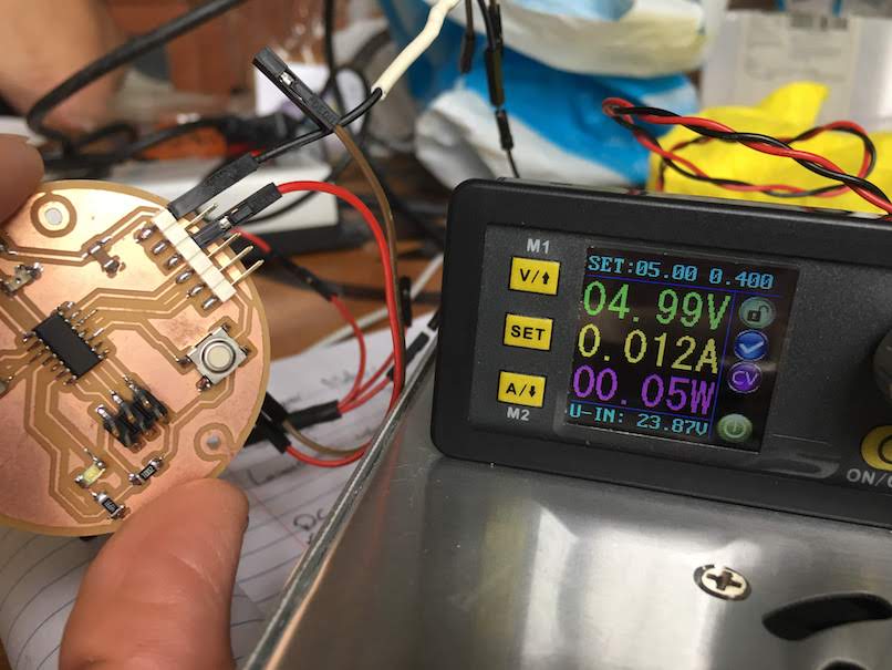
For this group assignment we are going to measure the power consumption of a LED on our microcontroller.
We upload the code to our microcontroller that turns a LED on and off an then measure the difference.
We measure the difference with a powerbank.
First we set our desired voltage and current, then we connect the GND and VCC of the powerbank to our board GND and VCC.
This powerbank supports setting the output voltage (5V) and current (1A) and shows the powerconsumption in both current as watt.
We see that when the LED is off we measure a 0.011A consumption and when the LED is on a 0.012A consumption.
So our LED concumes 1 mA.
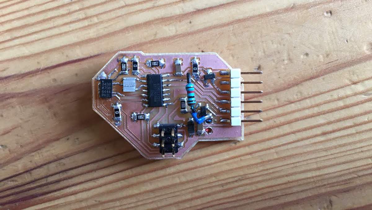
Creating a PCB with vibration motor
In this exercise we are going to create a microcontroller board with a vibration motor.
We will walk through the following steps:
Steps
- deciding on output
- finding circuit examples
- translating circuit to available parts of fabacademy
- designing scheme
- designing board
- milling
- soldering
- testing
- software
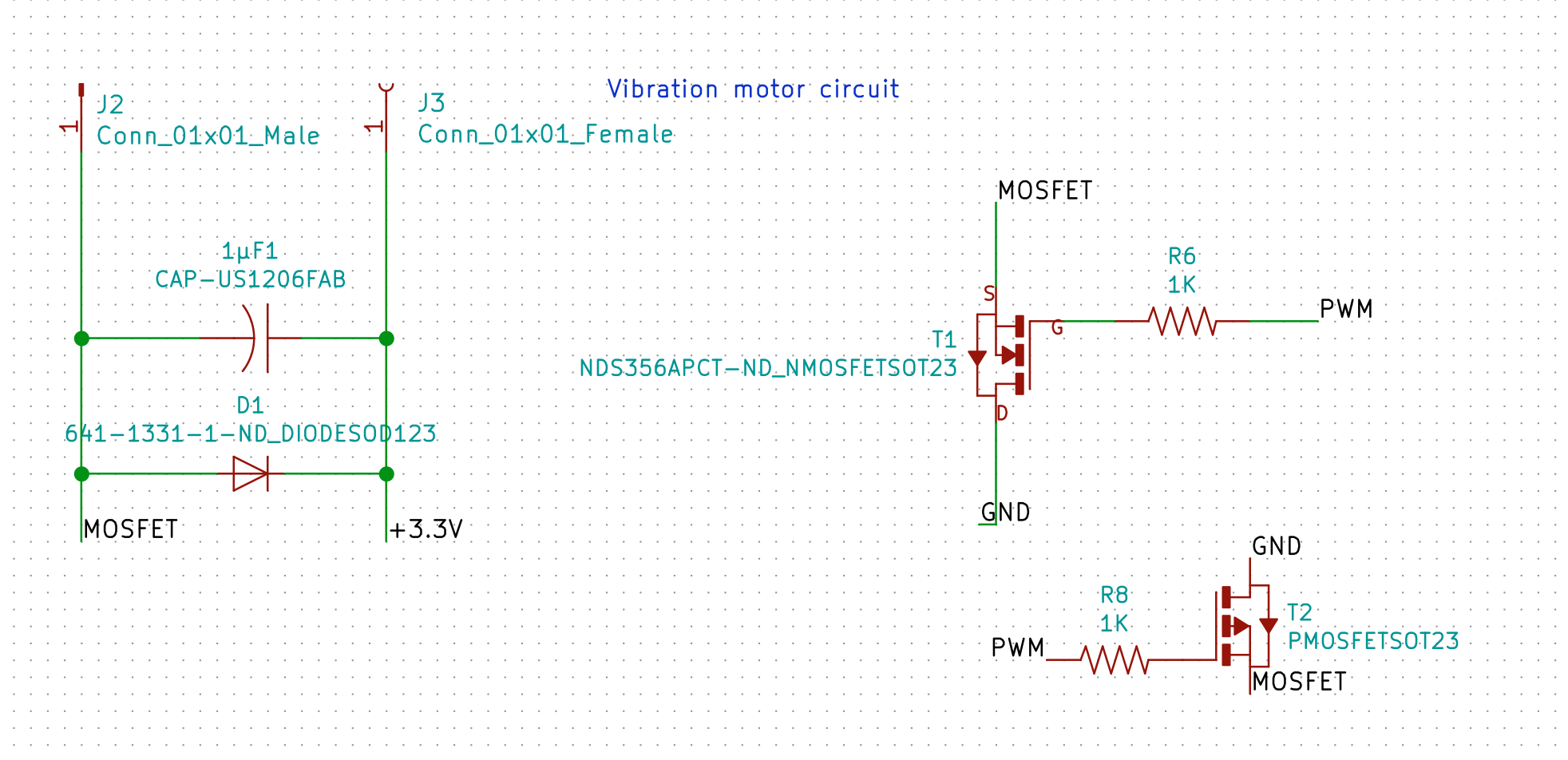
Vibration motor circuit
This week I will be designing a board that can vibrate. This is a direct step towards my final project, where I want to create an accessible vibrating smartband for people with a visual impairment.
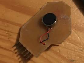
I decided to take a basic step and to use a basic vibration motor. These types of motors are DC motors that are out of balance because of an added weight. When running the motor the weight turns around and gives the sensation of vibration.
DC motors start spinning by supplying a voltage on one of the wires, and connecting the other wire to ground. If you switch the wires the motor will turn the other way around. Only, when you stop supplying voltage the motor does not stop directly, it will continue spinning for a short while.
During this down spin it will generate a voltage on its input pin. If you would connect the input pin directly from your microcontroller to the motor you can break your microcontroller due to the generated voltage. A motor controller board or chip can solve these problems, but I wanted to create something myself that can handle this voltage problem.
On the “Learn about Electronics” website I found a circuit that claims to resolve the problem that comes with the generating of voltage on the input pin.
The circuit used a diode to controll the flow of the current ( a diode is a component that allows current to only flow one way),
and a capacitor to catch the voltage peeks,
that are connected paralel to the vibration motor.
Next problems with DC motors is that they can draw more current than your microcontroller can provide. You can resolve this by supplying the DC motor with its own votlage input, and turning the input on/off/lower/higher with the microcontroller. You can either use a switch, transistor or mosfet to controll the voltage for the motor. The “Learn about Electronics” circuit also included a transistor (NPN Transistor 2N2222) for supplying the voltage.
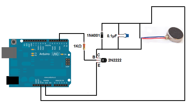
From the example scheme I had the following components:
- vibration Motor
- diode 1N4001 (50V 1A Diode)
- capacitor 0.1µF
- resistor 1 kOhm
- NPN Transistor 2N2222
These components are not fitted for SMD soldering. So I had to convert them to smaller/different components. In searching for the components, I stumbled on the FabAcademy website of Silvia Pallazi, she had the exact scheme used from the “Learn about electronics website” and converted the components to the FabAcademy part list. I could not be more lucky!
I still had to check if she did not made any mistakes and if we still had the same parts, or if I could find better parts, still it did save me hours of searching.
I checked the diode 1N4001 on diodes.com and found the diode is a 50V 1A diode. I can replace this with a Schottkey 100V 1A Diode .
I almost replaced it with a Schottkey 100V 150mA diode, but then realized 150mA is not enough to catch the peeks from the vibration motor.
MOSFET
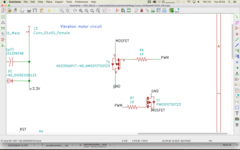
For the NPN transistor I read the blog of Silvia that she used a MOSFET, I looked if I could find a NPN transistor from the fab list that matched our criteria, but could not find one. So I also went for the MOSFET. A MOSFET can be used as a switch, for example to regulate voltage to a motor. With a MOSFET we can not only switch the voltage on or off, but also regulate the amount of current that flows through. The Mosfet I will be using is the NDS356AP-D. This is a P-type MOSFET (I did not realize this at this point, but it is important later. ;) )
To learn more about MOSFETS and how to use them I read the website: elprocus.com, there we read:
"The charge carriers enter the channel at SOURCE and exit via the DRAIN. The width of the channel is controlled by the voltage on an electrode is called GATE which is located between source and drain."
So a MOSFET has 3 legs, each with its own function:
- Source = Voltage in
- Drain = Voltage out
- Gate = Regulator pin for output Voltage
As can be seen in the schematic design I connected my PWM pin 5 to the Gate of the MOSFET with a 1KOhm resistor inbetween.
I connected the Source pin to the out part of my vibration motor circuit, which should be around 3.3V, since the vibration motor is directly connected to the 3.3V.
And I connected the Drain pin to the GND of my board.
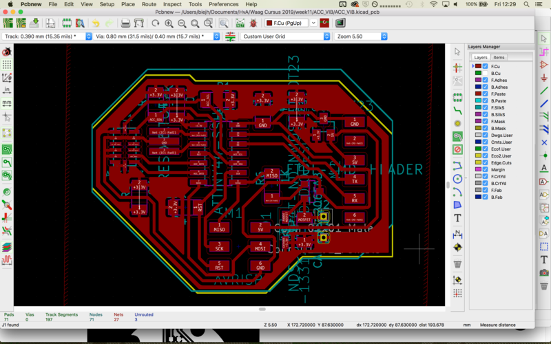
Schematic and PCB design
Knowing my components I could design schematic and board in KiCad.
I started with KiCad Schematics, and designed the basic schematics using the board design I made in week 7.
I removed the parts I did not needed and added my new components and vibrator scheme.
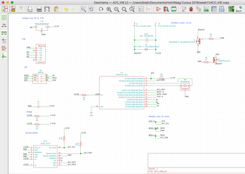
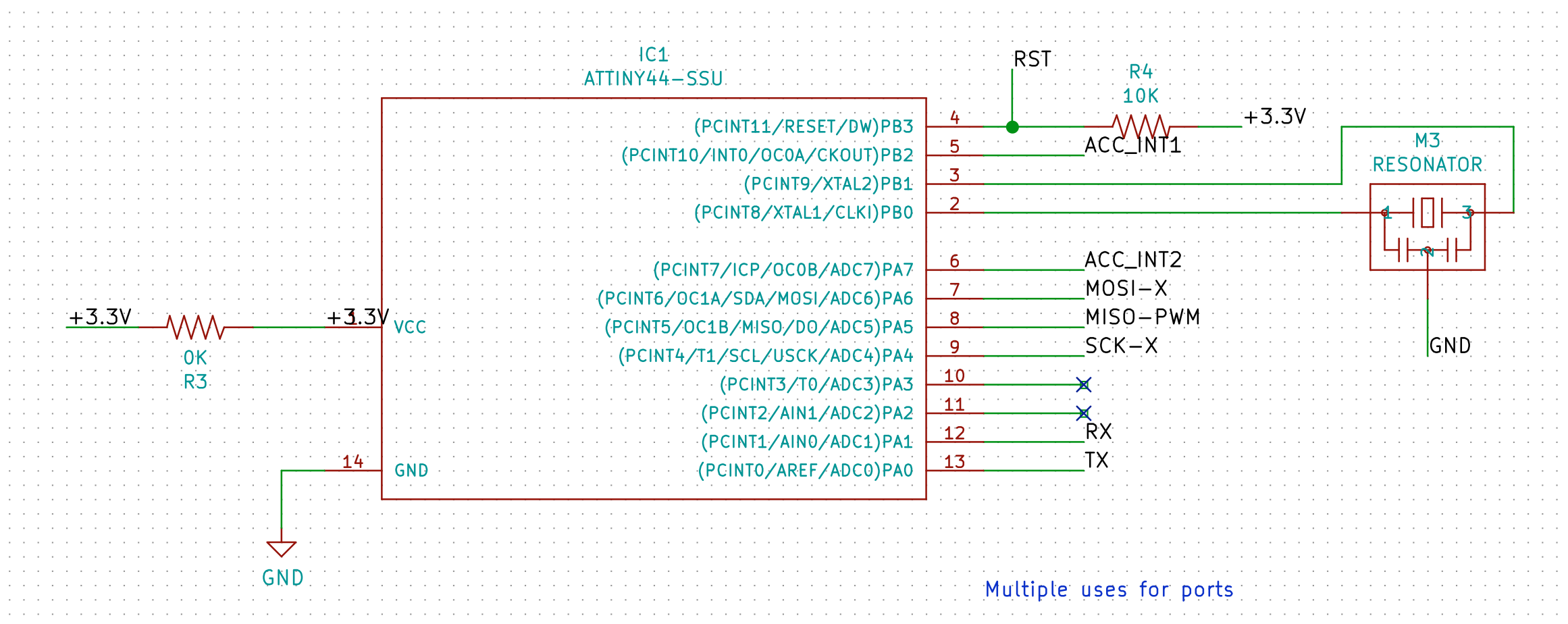
I also designed the parts for week11 in this design with an accelerometer, this resulted in using almost all the ATTiny ports and much difficulties in finding room for connecting everything.
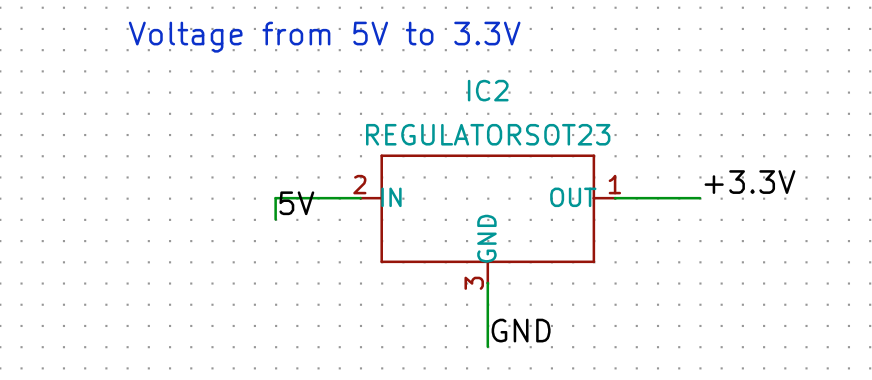
For my accelerometer I had to use 3.3V instead of 5V, and this is also fine for my vibrator, therefor I decided to make the whole board 3.3V instead of 5V.
I included a 3.3V regulator that directly converts the 5V from the FTDI or ISP preventing me to blow up my accelerometer.
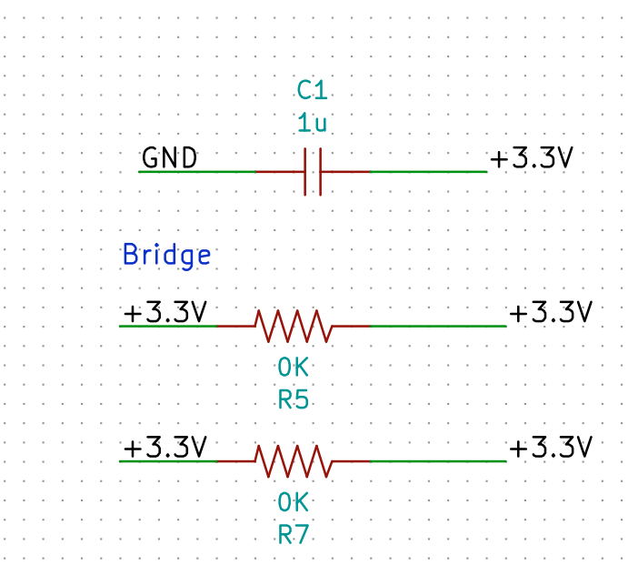
Especially with the PCB design I had trouble with tracing the wires. The accelerometer needed many traces and I switched back and forward many times between the PCB design and the schematic changing dedicated pins and eventually adding multiple 0k resistors to make a working board. Due to time constraints I also dropped my nice round design. I save time by letting the board size be determined by an easy to route components order.
For the vibration motor I had to use a PWM capable port. Most of these ports were allready used either by the accelerometer or the SPI interface. I ended up reusing one of the SPI interface pin for my vibration motor.
I also wanted to make a nice footpath for my vibration motor with a hole in the board, this would allow me to put the vibration motor on the bottom of my board and flow the wires through my board. In the components library of KiCad I found header holes to use for my vipration motor, I selected two female 1mm headers. They had a small how in the middle, which I could flow my wires through. (At least I thought, during the cutout export it turned out these holes are not exported)
Milling
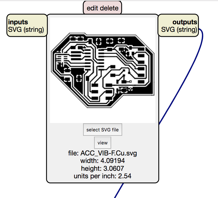
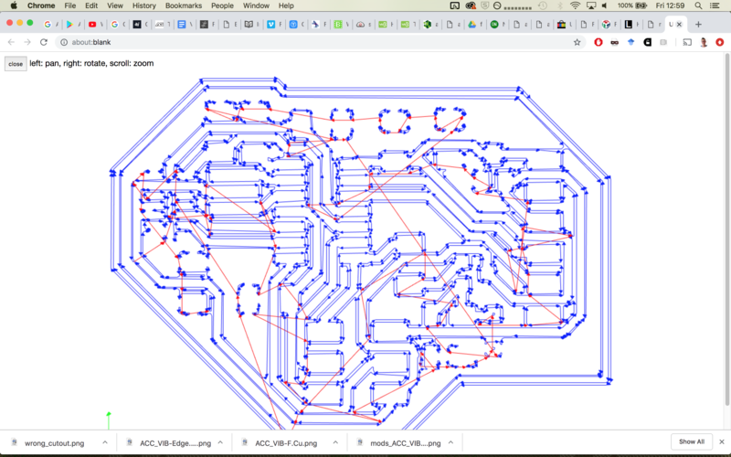
To mill I had to export the PCB design to a PNG.
I actually did not had to export to png, mods now supports SVG for the modella 20x! Yes!
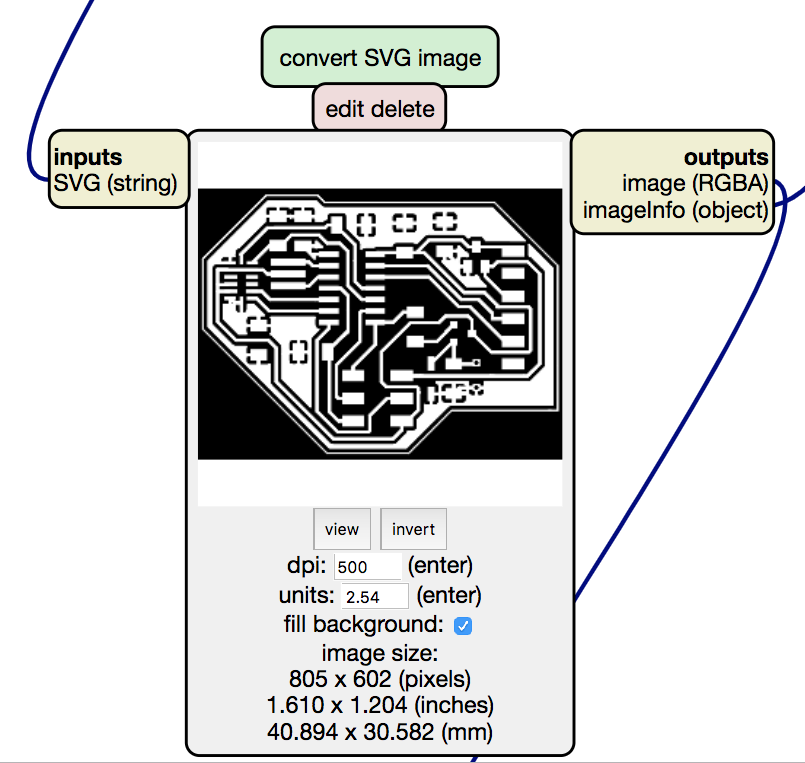
Eventually I still created a png file from each svg, but now using the mods software not the cloudconvert website I used in week7, I first loaded the svg than inverted the image and then viewed the PNG at 500dpi and save it as a PNG.
Also I had to edit the cutout file, since it had a full white lines instead of a white and black field.
After exporting the cutout file, I saw there were no holes for the vibration motor.
I solved this by drawing small circles of 0.44 mm diameter on a special layer and exported them to a new svg file. (this turned out to be a mistake, since my cutout mill is a 0.8mm mill not a 0.4 mm mill, so I had to double my diameter).
The file I inverted and then converted to a PNG using the mods PNG module.


For the milling process I took my notes from week 5 as a base.
I did not changed anything to these settings compared to week 5.
The tracelines went really smooth and with no errors.
After the tracelines I took my drill holes for the vibration motor and went through the cutout process. This did work, but gave to large holes (see “Drill holes not matching” fail). Next time I will drill on the inside of these lines.
Besides forgetting to set the correct DPI (see fails “Milling in the air”) the cutout went smooth.
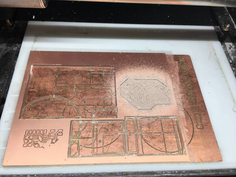
After milling I checked my traces and saw no errors.
Tested basic connections and 3.3V. with voltage meter and it looked all good.
On to soldering.
Soldering
I went through my steps from week 5 for the soldering:
- Remove extra material
- Clean board with soap
-
Find and order components
- Solder from inside to outside, from small to large
Programming
Burning bootloader
I encountered an error while burning the bootloader.
I tested the setup with my old working board, this worked,
and double checked my pin layout. This looked fine.
Arduino: 1.8.8 (Mac OS X), Board: "ATtiny24/44/84, ATtiny44, External 20 MHz"

/Applications/Arduino.app/Contents/Java/hardware/tools/avr/bin/avrdude -C/Applications/Arduino.app/Contents/Java/hardware/tools/avr/etc/avrdude.conf -v -v -v -v -pattiny44 -cusbtiny -e -Uefuse:w:0xff:m -Uhfuse:w:0xdf:m -Ulfuse:w:0xfe:m

avrdude: Version 6.3-20171130
         Copyright (c) 2000-2005 Brian Dean, http://www.bdmicro.com/
         Copyright (c) 2007-2014 Joerg Wunsch

         System wide configuration file is "/Applications/Arduino.app/Contents/Java/hardware/tools/avr/etc/avrdude.conf"
         User configuration file is "/Users/biejh/.avrduderc"
         User configuration file does not exist or is not a regular file, skipping

         Using Port                    : usb
         Using Programmer              : usbtiny
avrdude: usbdev_open(): Found USBtinyISP, bus:device: 020:013
         AVR Part                      : ATtiny44
         Chip Erase delay              : 4500 us
         PAGEL                         : P00
         BS2                           : P00
         RESET disposition             : possible i/o
         RETRY pulse                   : SCK
         serial program mode           : yes
         parallel program mode         : yes
         Timeout                       : 200
         StabDelay                     : 100
         CmdexeDelay                   : 25
         SyncLoops                     : 32
         ByteDelay                     : 0
         PollIndex                     : 3
         PollValue                     : 0x53
         Memory Detail                 :

                                  Block Poll               Page                       Polled
           Memory Type Mode Delay Size  Indx Paged  Size   Size #Pages MinW  MaxW   ReadBack
           ----------- ---- ----- ----- ---- ------ ------ ---- ------ ----- ----- ---------
           eeprom        65     6     4    0 no        256    4      0  4000  4500 0xff 0xff
                                  Block Poll               Page                       Polled
           Memory Type Mode Delay Size  Indx Paged  Size   Size #Pages MinW  MaxW   ReadBack
           ----------- ---- ----- ----- ---- ------ ------ ---- ------ ----- ----- ---------
           flash         65     6    32    0 yes      4096   64     64  4500  4500 0xff 0xff
                                  Block Poll               Page                       Polled
           Memory Type Mode Delay Size  Indx Paged  Size   Size #Pages MinW  MaxW   ReadBack
           ----------- ---- ----- ----- ---- ------ ------ ---- ------ ----- ----- ---------
           signature      0     0     0    0 no          3    0      0     0     0 0x00 0x00
                                  Block Poll               Page                       Polled
           Memory Type Mode Delay Size  Indx Paged  Size   Size #Pages MinW  MaxW   ReadBack
           ----------- ---- ----- ----- ---- ------ ------ ---- ------ ----- ----- ---------
           lock           0     0     0    0 no          1    0      0  9000  9000 0x00 0x00
                                  Block Poll               Page                       Polled
           Memory Type Mode Delay Size  Indx Paged  Size   Size #Pages MinW  MaxW   ReadBack
           ----------- ---- ----- ----- ---- ------ ------ ---- ------ ----- ----- ---------
           lfuse          0     0     0    0 no          1    0      0  9000  9000 0x00 0x00
                                  Block Poll               Page                       Polled
           Memory Type Mode Delay Size  Indx Paged  Size   Size #Pages MinW  MaxW   ReadBack
           ----------- ---- ----- ----- ---- ------ ------ ---- ------ ----- ----- ---------
           hfuse          0     0     0    0 no          1    0      0  9000  9000 0x00 0x00
                                  Block Poll               Page                       Polled
           Memory Type Mode Delay Size  Indx Paged  Size   Size #Pages MinW  MaxW   ReadBack
           ----------- ---- ----- ----- ---- ------ ------ ---- ------ ----- ----- ---------
           efuse          0     0     0    0 no          1    0      0  9000  9000 0x00 0x00
                                  Block Poll               Page                       Polled
           Memory Type Mode Delay Size  Indx Paged  Size   Size #Pages MinW  MaxW   ReadBack
           ----------- ---- ----- ----- ---- ------ ------ ---- ------ ----- ----- ---------
           calibration    0     0     0    0 no          1    0      0     0     0 0x00 0x00

         Programmer Type : USBtiny
         Description     : USBtiny simple USB programmer, https://learn.adafruit.com/usbtinyisp
avrdude: programmer operation not supported

avrdude: Using SCK period of 10 usec
CMD: [ac 53 00 00] [00 00 00 00]
avrdude: AVR device initialized and ready to accept instructions

Reading | CMD: [30 00 00 00] [00 00 00 00]
CMD: [30 00 01 00] [00 00 00 00]
################CMD: [30 00 02 00] [00 00 00 00]
################################## | 100% 0.00s

avrdude: Device signature = 0x000000 (retrying)

Reading | CMD: [30 00 00 00] [00 00 00 00]
CMD: [30 00 01 00] [00 00 00 00]
################CMD: [30 00 02 00] [00 00 00 00]
################################## | 100% 0.00s

avrdude: Device signature = 0x000000 (retrying)

Error while burning bootloader.
Reading | CMD: [30 00 00 00] [00 00 00 00]
CMD: [30 00 01 00] [00 00 00 00]
################CMD: [30 00 02 00] [00 00 00 00]
################################## | 100% 0.00s

avrdude: Device signature = 0x000000
avrdude: Yikes!  Invalid device signature.
         Double check connections and try again, or use -F to override
         this check.


avrdude done.  Thank you.
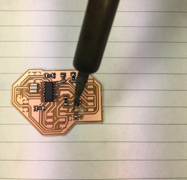
Next I checked with the voltage meter and found 3.3V and GND to be connected. (I should have done this before I tried to install my code offcourse!)
I could not find where my 3.3V was connnected to GND, so I decided it was the accelerometer, since this was a very difficult component to solder and had the 3.3V and GND pins close to eachother.
I could not remove the accelerometer with a solder iron, so I tried to remove the accelerometer with the heatgun. Big mistake, this broke my traces and the accelerometer and I still had the connected 3.3V and GND!

Next I tried to remove the 3.3V converter, since on my PCB design board I saw that the 3.3V and GND were close to eachother. After removing the convert I still had the 3.3V connected to GND, so I placed the component back in its place.
After another 15 minutes of searching I found just under my ISP header a tiny piece of coper of about 0.4 mm that connected the GND to the 3.3V.
Looking back at the pictures I took, I did not find this piece, I guess I placed the small piece between my header and my board when I soldered the header on my board.
After removing this with a tweezer, I was able to burn the bootloader on the board.
I checked to see if I could see the chip with avrdude, and this was also OK.
C02KR0SBFFRP:fotos biejh$ avrdude -c usbtiny -p t44

avrdude: AVR device initialized and ready to accept instructions

Reading | ################################################## | 100% 0.00s

avrdude: Device signature = 0x1e9207

avrdude: safemode: Fuses OK (H:FF, E:DF, L:FE)

avrdude done.  Thank you.
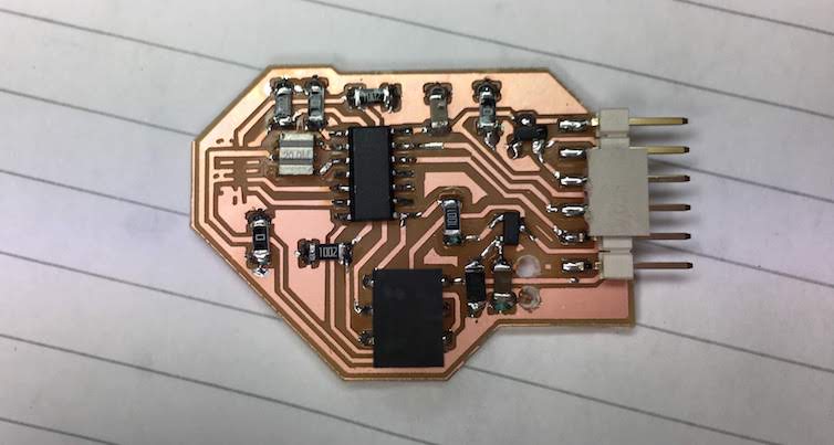
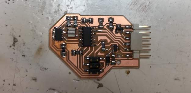
After having a working board I soldered in the vibration motor.
And tried the vibration motor by loading a simple on/off sketch.
const int motorPin = 5;

void setup()
{
pinMode(motorPin,OUTPUT);
}

void loop()
{
digitalWrite(motorPin, HIGH);
delay(1000);

digitalWrite(motorPin,LOW);
delay(10000);
}
Even before uploading the sketch the motor started spinning. How could that be?!
I measured my output pin with a voltage meter and saw the difference in voltage.
Next I tried PWM to see if this had any effect, and if I could measure this with my voltage meter.
int ledPin = 5;    // LED connected to digital pin 9

void setup() {
  // nothing happens in setup
}

void loop() {
  // fade in from min to max in increments of 5 points:
  for (int fadeValue = 0 ; fadeValue <= 255; fadeValue += 5) {
    // sets the value (range from 0 to 255):
    analogWrite(ledPin, fadeValue);
    // wait for 30 milliseconds to see the dimming effect
    delay(30);
  }

  // fade out from max to min in increments of 5 points:
  for (int fadeValue = 255 ; fadeValue >= 0; fadeValue -= 5) {
    // sets the value (range from 0 to 255):
    analogWrite(ledPin, fadeValue);
    // wait for 30 milliseconds to see the dimming effect
    delay(30);
  }
}
Again my voltage meter could measure it, and it had no effect on my vibration motor…
After reading on https://oscarliang.com/how-to-use-mosfet-beginner-tutorial/ I concluded the following:
It turned out I used a P type MOSFET while I used a circuit of a N type.
This means I had to pull the MOSFET to the GND instead of applying a voltage.
I tried if I could simulate this using the internal Pull-up resistor.
const int BUTTON_PIN = 5;     // the number of the pushbutton pin
// variables will change:
int buttonState = 0;         // variable for reading the pushbutton status

void setup() {
  //configure pin 3 as an input and enable the internal pull-up resistor
  pinMode(BUTTON_PIN, INPUT_PULLUP);
}

void loop() {
  // read the state of the pushbutton value:
  buttonState = digitalRead(BUTTON_PIN);
}
This code had no effect.
I also found that Silvia had the same problems. She found that you need a 10k Ohm resistor that pulls the MOSFET to the ground.
Like Silvia, I applied my resistor. I used a small piece of heatshrink around the resistor its legs to prevent any shortcuts.
Still no effect…
I read on about my MOSFET, and found the following:
“If load is connected at the source side, the Vgs will needs to be higher in order to switch the MOSFET, or there will be insufficient current flow between source and drain than expected.”
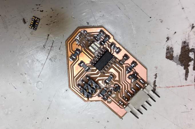
Also I noticed Silvia switched the Drain and the Source, I recheked my schematic and my traces, and decided I had to swith the Drain and the Source pins.
I desoldered the MOSFET, rotated it 180 degrees and connected the Source to GND and Drain to my vibration motor circuit. Then I made a tiny wire and connected the Gate again using this tiny wire. It was very difficult since I did not had small enough wires and a small enough solder tip.
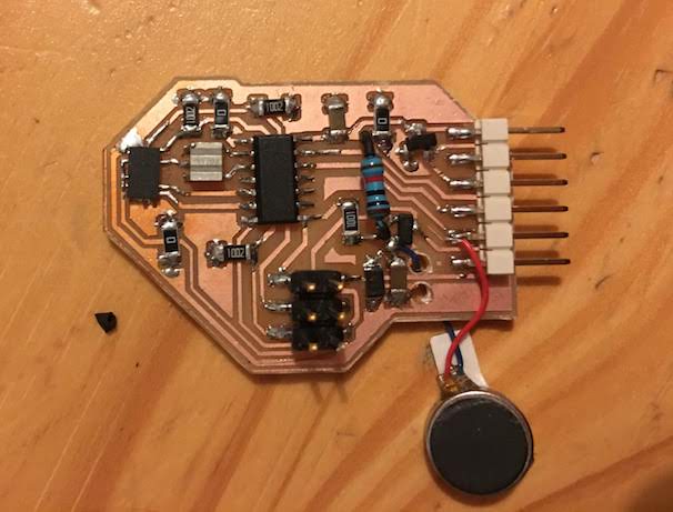
Still I managed, and the end result is a working vibration motor.
Vibration patterns
I tried several different vibration patterns in a test sketch -> Code for vibration pattern tests
From these test I determined optimal delay between patterns is 100ms when the pin is high (255) at analogWrite (maximum PWM).
Longer than 100ms makes the vibration feel very strong, between 200 and 300ms feels like the duration of smartphone patterns.
The lowest possible PWM strenght is analogWrite(50), but I would recommend 60 or 70.
When creating a fade-in or fade-out steps should not be bigger than 10, and thus start at 50.
A soft nod pattern is:
  analogWrite(ledPin, 255);
  delay(100);
  analogWrite(ledPin, 0);
  delay(100);
A short nod is:
  analogWrite(ledPin, 255);
  delay(50);
  analogWrite(ledPin, 0);
  delay(100);
Fails
Out-of-time (to complex)
Designing my first board in week 7 took me less time than I anticipated, I expected this time to also be an easy process.
My mistake, because I had used (alsmost) all the pins of the ATTiny, routing was way more difficult. Also I wanted to keep the round shape, to work towards my armband design.
After 4 hours of tracing wires and still not finished, I decided to drop the round design, and just see how big my design will be.
This solved many problems and after two hours and 2 extra 0K ohm resistors, I had a finished strange shaped design.
Milling in the air
After starting my cutout I noticed I kept milling in the air next to the bed, as if it was twice the x and y distance.
Tried a reset of the mill and reload of the mods software, this did not work.
Then I tried to shut down the mill, browser and terminal and reload everything.
After restarting and reloading the image I found that the problem was not the software or the X and Y settings or some strange memory error, but that I forgot to set the dpi to 500 instead of 72!
Drill holes not matching
After drilling the holes for the vibration motor, I noticed my holes are way bigger than expected.
It turned out I forgot to set the drill holes to 0.8 mm instead of 0.4 mm and to cutout within the line, it stead of oudside of the line.
Extra 0 Ohm resistors
After soldering I was left with some extra resistors. It turned out that during my multiple design sessions of the schematic and layout, I added and removed components. In stead of reanotating the existing components, I only annotated the new components. It appears that KiCad does not detect that the components that are not used and removed do not exist anymore, and it keeps them in the part list.
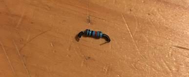
0kOhm instead of 1kOhm on the board
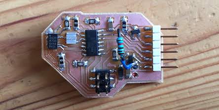
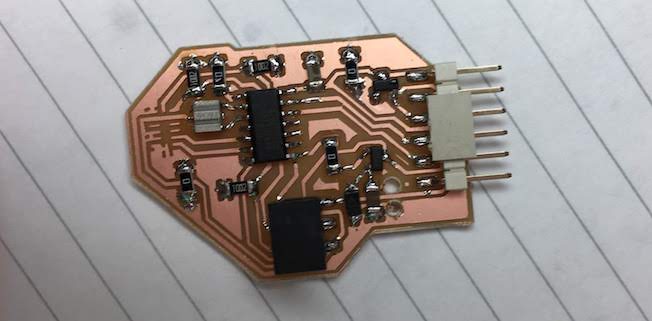
At the end of soldering I had a 1KOhm resistor left. It turned out I had soldered a 0k resistor instead of a 1k resistor. I replaced the resistor, see the pictures for the difference.
Reflection
This week I made almost every mistake I could make,wrong components, wrongly placed components, broken components, did not checked ok, did not read datasheet ok, still I ended up with a working board in the end.
Next time I will build in periodical checks, and try to work out things more before I actually start milling, als I want to work with more iterations if I can find the time for this. These 3 steps will allow me to encounter my mistakes earlier than at the end of the week, allowing me to fix them sooner.