Week 20. Project development
20. Project development
Files
TIKTOK micocontroller code (Arduino) with accelerometer, vibration and BLE
TIKTOK Android application
Illustrator arm band design
Laser arm band instruction code
Smart watch case and cover Fusion360
Ultimaker file watch case
Gcode Ultimaker watch case
Cover stl
Cover Gcode Prusa
Software
Adobe Illustrator, for 2D modeling, armband design
Fusion360, for 3D modelling, body and cover design
Ultimaker Cura, for printing body
Prusa slicer, for printing cover
Laser Cutter 5.3 - the software to format illustrator file to laser cutter code
For prototypes:
KiCad, open source electronics design tool suite.
Mods, control software for the Roland mill
PartWorks 3D (software for translating mold design to G-code for the Shopbot)
Shopbot controll software (for sending the G-code to the Shopbot)
Arduino IDE (Simple IDE to program especially Arduino based microcontrollers)
AVRDude (the AVR programming application used and integrated in the Arduino IDE)
Android Studio, for writing the Android app
Hardware
Prusa i3 MK3S MMU2S, for cover 3D print
Ultimaker 2+, for body 3D print
Laser cutter, for leather arm band
Protomat S62, mill for PCB
Multimeter, for checking traces
Knife, for cutting wires
Anti static tweezers, for electrical components
Solder iron, for soldering components
Solder tin, for SMD components soldering
Various surface mounted components (see BOM and PCB design files)
A regulated digital controlled DC power supply, to test initial power usage
Macbook Pro 15 inch, 2015 edition, for programming board and Android app
ISP programmer, USBtiny, made in week 05
A USB to TTL controller. (also know as a FTDI controller)
Motorola Moto G 2nd edition, for Android application
Micro usb cable, for uploading code to Android application
For prototypes:
Shopbot, for milling mold
Wax, for first mold
Smooth cast, for final cast
PCM, for flexible mold cast
Roland Modella MDX-20 mill , for milling prototypes
with the mill bit for traces - mini end mills two flutes 0.40 mm 826 (damen.cc)
with the mill bit for cutout - two flutes 0.8 mm
Assignment
“Complete your final project tracking your progress.”
What has worked? what hasn’t?
Looking back at the past 20 weeks, I have learned a lot and mostly made it work.
Especially the electronics is something that I have learned and now mostly works. I learned to design with KiCad, mill and solder SMD components. Further I explored all kind of in and output devices for my final prototoype.
Still my previous prototype board was not perfect, I made an error in my vibration motor design, could not solder the accelerometer with a heat gun, and in the end broke my 3.3V prototype board. I explored concepts as ground pore, round PCB design, and mounting holes.
I still need to explore double sided design. This is something I cannot easily do with the Modella, but at the Makerslab at my work we have a different PCB mill that can do double sided milling. For my final board I will explore that device, but it means I need to learn EAGLE in stead of using KiCad.
With laser cutting everything went smooth, no big problems, just a lot of iteration to find the correct settings.
With 3D printing I learned how to use the devices, and design for them in Fusion360 and OpenSCAD.
But I did not jet printed a large piece for my final project.
The milling projects and molding and casting took me a lot of time, I learned how to properly use the Shopbot, but am not satified with the amount of time 3D milling takes given the result. In the end I was only able to create one prototype for that week, and it was not as nice as I hoped. Exploring this concept to get the desired outcome might take me a lot of time. I think it is better for my final design to first explore the 3D printer more and try to create a sturdy case with the 3D printer instead of casting it.
What questions need to be resolved?
Summarising the previous text:
- How to create small double sided board.
- Learn EAGLE
- How to create a sturdy case (3D print or cast?)
- Learn how to laser cut with leather
- Explore smaller Bluetooth board RN4871
- Write software for Bleutooth board (app and microcontroller)
- Make all the individual parts work together
What tasks have been completed, and what tasks remain?
My whole project is partially executed through all the past weeks. In week 13 I had defined the following requirements:
- Recognise tap gestures via accelerometer
- Vibrations as output
- Has at least one button for input
- Create Bluetooth app and communicate with microcontroller
- Can work standalone as watch (tap pattern for getting time in vibrations)
- LED indicators (for debugging)
- USB-port for power and programming
Optional: - Uses (rechargeable) battery
- Long battery life: last at least a day preferable a week or longer
For this I defined the following tasks:
| Task | Explored in weeks | Remaining time | ToDo |
|---|---|---|---|
| Recognise tap gestures via accelerometer | week 11 | 4 hours | can work with accelerometer, not recognise taps |
| Vibrations as output | week 9,week 12 | 1 hour | connect vibrations to serial |
| Has at least one button for input | week 7 | 0 | complete |
| Create Bluetooth app and communicate with microcontroller | week 14 | 16 hours | Switch MH10 to RN4871, Improve Android app code |
| Design board | week 5 ,week 7 ,week 11 , week 12 | 24 hours | Learn EAGLE, Double sided PCB, New mill, Solder, Debug |
| design and create case | week 3 ,week 6 , week 10 | 4 hours | Update design for new board and 3D print new design, or mold |
| Design and create arm band | week 4 | 4 hours | Design and cut arm band |
| (optional) explore rechargeable battery | none | 8 hours | get battery, explored module, ect |
| (optional) explore battery life improvements | none | 8 hours | everything |
| Total | remaining 64 hours | planned 67 hours |
This was allready to much. I decided to drop the optional parameters, leaving me with about 50 hours of working time for the final project.
Next up there was also other activities remaining for presenting the final project and finishing the remaining weeks:
| Task | Explored in weeks | Remaining time | ToDo |
|---|---|---|---|
| Create final presentation slide and movie | week 19 | 4 hours | drafts finish, update day before presentation |
| finish wildcard week | week 19 | 8 hours | design made, other stuff not |
| finish documentation of previous weeks | week 3 ,week 13 , week 17 , week 19 | 20 hours | week 3 describe other apps, week13 elaborate on notes, week 17, elaborate on notes, week 19 wrap up |
| finish documentation of final project | week 20 | 16 hours | Document as you go, elaborate on notes |
| Total | remaining 16 hours | planned 36 hours |
Everything together leaves me with 86 hours of work, while I have around 60 hours of time.
The documentation of the final project maybe will not take this much time,
still I want to leave some room for errors.
To buy more time, I decided to also add the Saturday and Sunday to the remaining time, bying me 16 hours of extra time.
Also I would schedule my time in my calendar en work according to that time, if something is not finished in that set time, I either will skip it, or sacrifice time from something else to finish it.
What will happen when?
My deadline is Wedneday 19th of June.
My planning for the coming weeks is as follows:
- Monday June 3rd: make planning
- Tuesday June 4rd: learn new PCB mill (4 hours), finish week 19 (4 hours)
- Wednesday June 5th: learn EAGLE, design new board (8 hours)
- Thirsday June 6th: finish board design (4 hours)
- Friday June 7th: make and solder board (8 hours, 1 hour wait), finish week 18 activity (4 hours), print case (1 hour work, 3 hours wait)
- Monday June 10th: (optional) finish soldering and test board ( 8 hours)
- Tuesday June 11th: test board ( 4 hours), finish wildcard week documentation ( 4 hours)
- Wednesday June 12th: finish Bluetooth part ( 8 hours)
- Thirsday June 13th: create arm band (4 hours), print case top ( 1 hour design, 3 hours wait)
- Friday June 14th: finish vibration part ( 2 hours), finish accelerometer part (8 hours)
- Saturday June 15th: finish documentation remaining weeks
- Monday June 17th: finish final project documentation ( 6 hours)
- Tuesday June 18th: extra time ( 8 hours)
In total I have 92 hours planned, but a lot of things have overlap, because of machines that do the work.
At least 7 hours are machines working, bringing me back to about the time I had created in my table, 92-7=85 hours.
Reflection, What have you learned?
Looking back on Saturday June 15th, My planning worked ok.
Designing in EAGLE was way more difficult than expected. I had to drop all extra design considerations, and just make a small board as fast as possible. This resulted in me dropping the inclusion of onboard battery management, the charging module, the inclusing of onboard USB connector, the inclusion of a onboard accelerometer, taking the time to arrange every debug header ergonomical, and last to make the board really as tiny as I could. I think with a week of 2 of extra time, I can shrink the board to half its current size, include an onboard accelerometer and have battery management, and losing all de big debug headers.
The soldering and programming of my board took way longer than expected, therefor I had to use the optional day June 10th.
Also the programming of the Bluetooth board and did not went as smooth.
I worked on it the whole Wednesday June 12th for 10 hours, Friday 14th for 4 hours and Saturday 15th for 2 hours.
I also needed more time for the accelerometer than expected.
Since I did not wanted to drop the accelerometer, vibration motor or Bluetooth, I sacrificed design of the Android app.
It is now a very basic app, without external API, but this can be very easily created.
I also sacrificed sleep. Friday I worked untill Saturday 3 AM.
But now I have a working board pretty much with the requirements I designed.
Next up the work I did these past weeks, I will also copy these relevant sections to their related weeks, and keep updating this section untill the final project is finished. A distilled version of this will be on my final project page.
3D print body
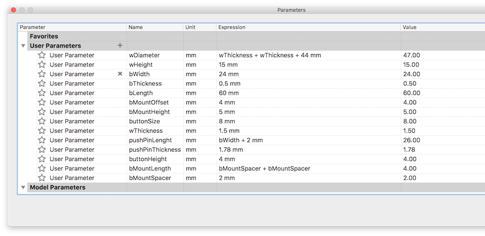
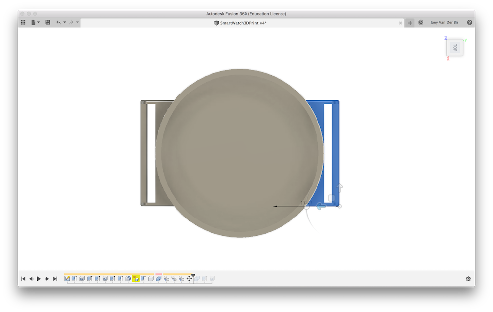
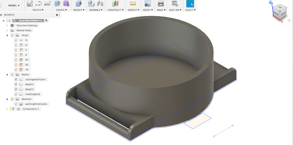
For my final body design I opened my molding design and changed the width parameter to fit my new board size.
Fusion360 automatically updated the size of my bodies to the new parameters.
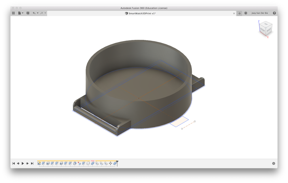
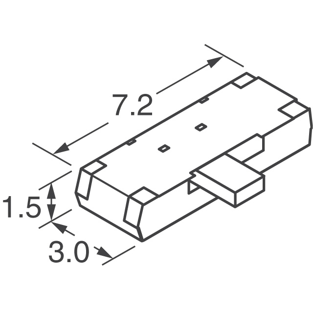
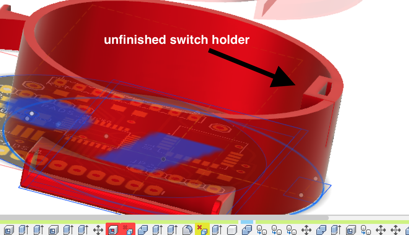
I added a mount for the on/off switch.
The datasheet provided the dimension, that I copied to my parameters in Fusion360.
I started on adjusting my button/switch holder, I extracted the rectangle from my sketch, than wanted to make a hollow form out of my new cube.
Then something happened: TRIAGE!
I had reached the time to start my 3D print. It was Friday and around 1400. If I really wanted to print a case that day, I had to finish my design in a few minutes. I had to drop my holder for the switch, and just print the design I created earlier.
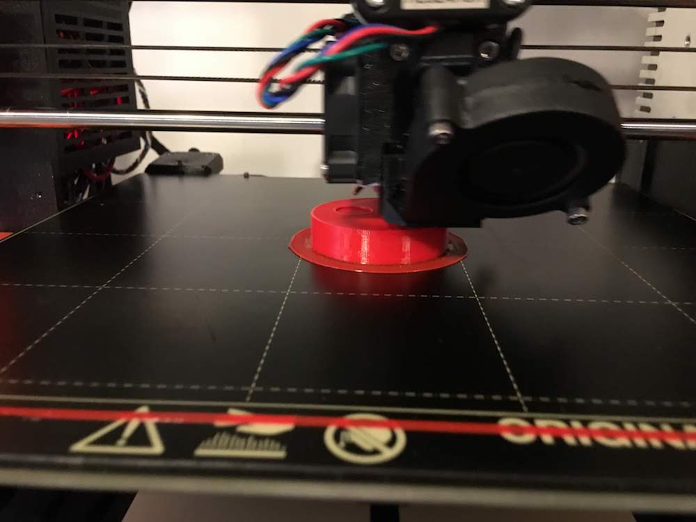
After this painfull decision, I took the Ultimaker 2+, exported my design from Fusion to Cura, and copied my specifications from my previous description. With an infill of 20% it will the Ultimaker take about 1,5 hours, not bad.
I added a build plate and supports. The build to prevent the print from moving, and the supports for my small cutout I made at the bottom for the armband.
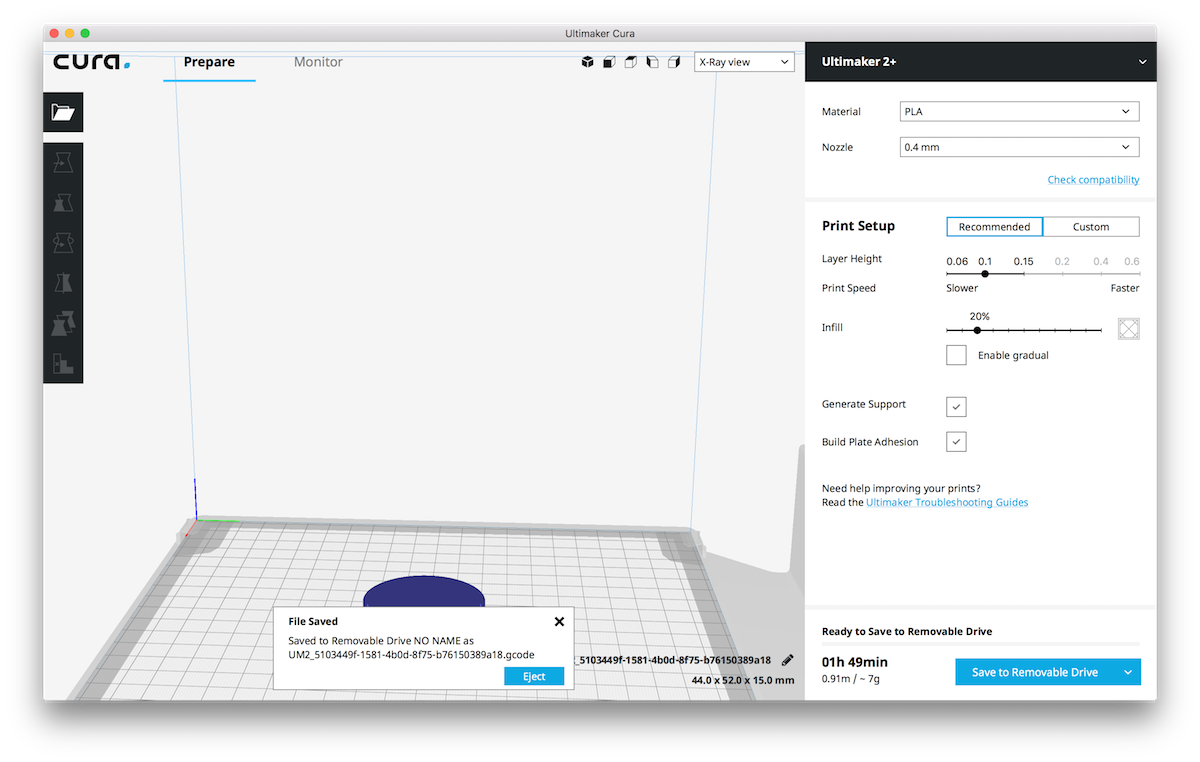
I switched filament from black to white and performed a first test print of a small servo arm of our group machine to make sure there was no more black in the nozle, and I had the device properly calibrated.
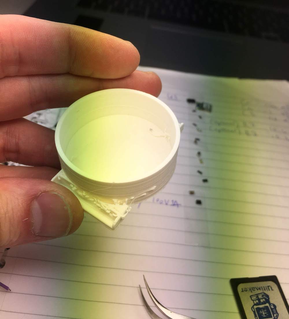
After the servo arm was finished I loaded my case design.
After 1,5 hours it was finished. And the result looked nice, besides that one of the arm band mounts was 2 mm off!
I checked my design, and just before exporting I accidentally moved the mount with my mouse!
I fixed my mistake, reexported to cura and exported to the Ultimaker.
This time printing went succesfull.
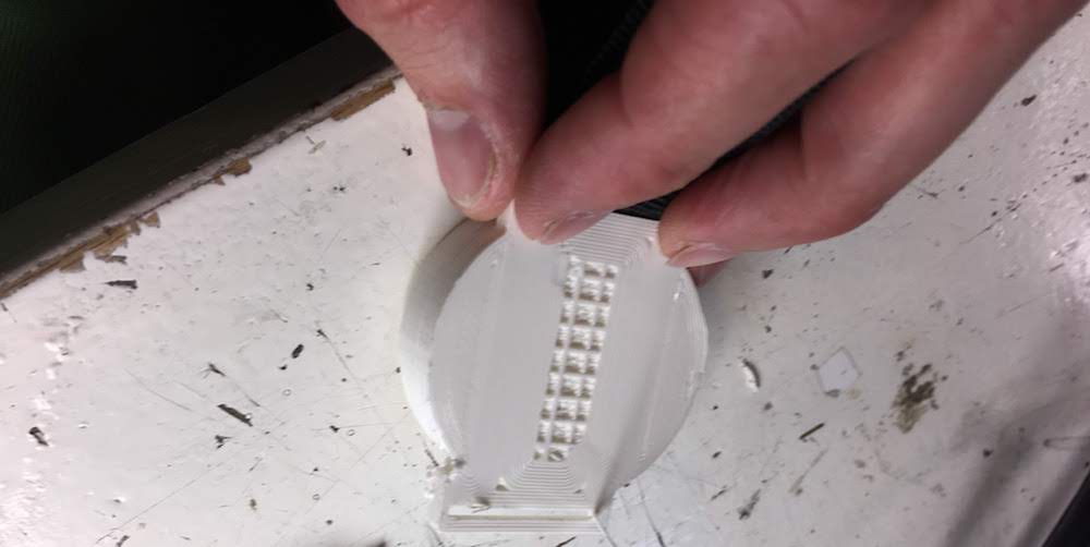
One thing that still went wrong was that the support was fused to my small cutout for the armband.
I accepted this fail, since the other parts of the body were perfect, and you wont see this mistake when wearing the watch.
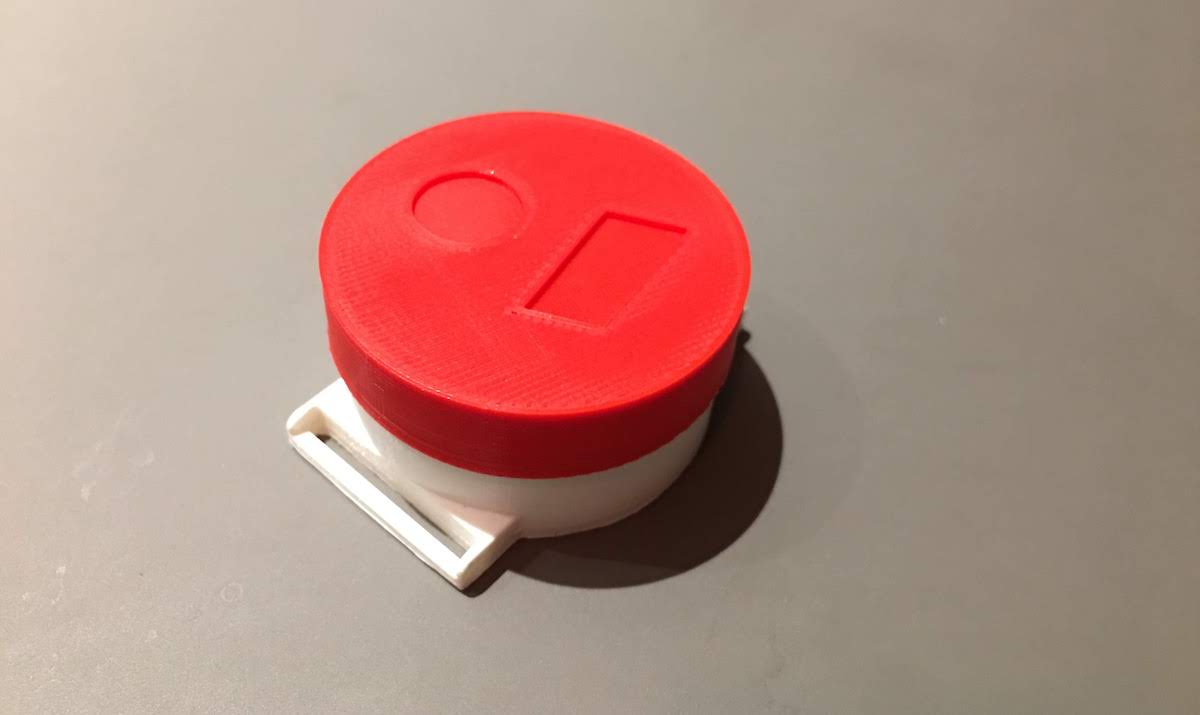
3D print cover with prusa
After having a working body, I found an extra hour to design a cover for my body.
Although I tried to keep it simple it became complex fast.
First I started by extracting the circle of my watchsketch, and them adding about 0.1 mm to make sure my cover would be a little bit larger than the body. I noticed my electronics was allready sticking out of the watch case, so I made my top 7mm high to make sure all the electronics would fit.
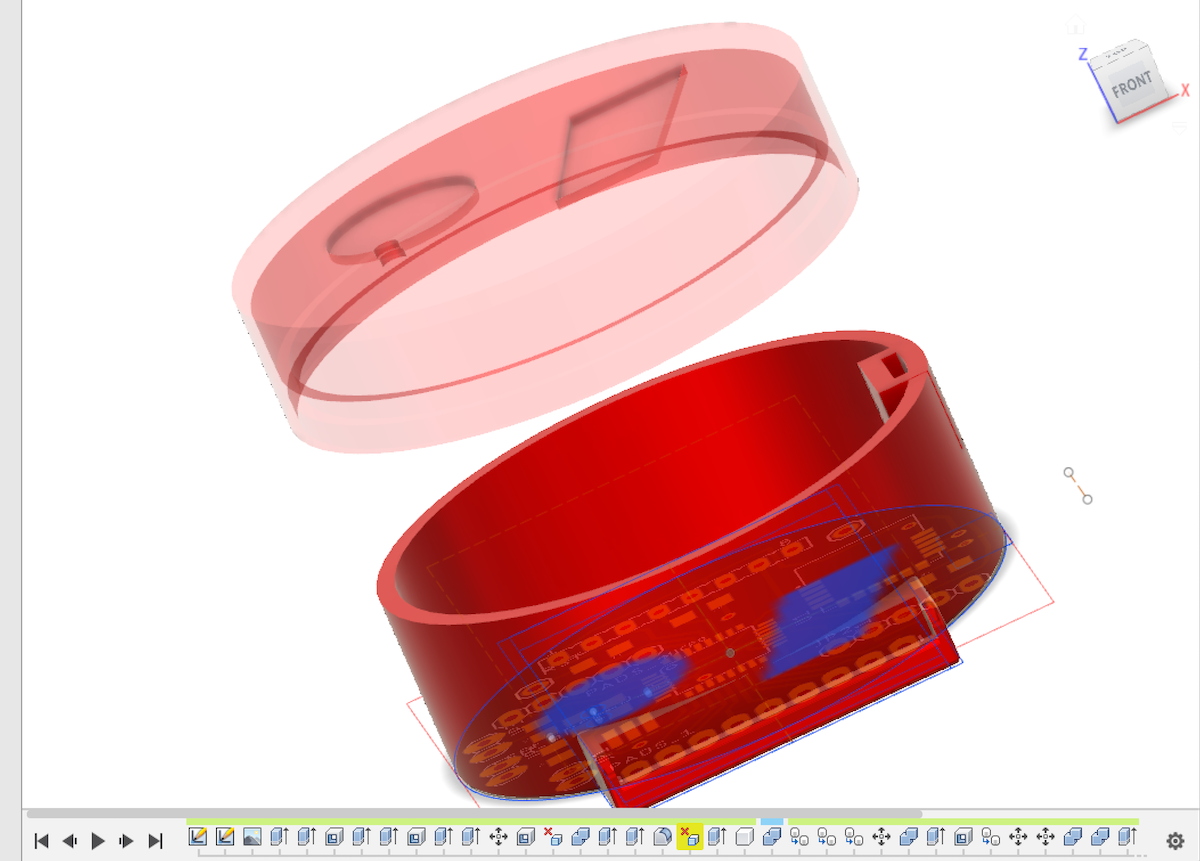
Next I made a shell of my cilinder, but keeping the top solid.
To make sure the whole cilinder would not slide over my watch case, I had to ad some form of legs inside my cover to stop at the edge of my watch case.
I decided to extract another cilinder from my watch circle from the sketch, but only making it 1 mm high and then making a shell out of it off about 1 mm width. So I ended up with a small ring that would fit exactly on top of my watch cover.
I combined the ring and cover on about a 1 mm height, giving me the stop at the edge of my watch inside my cover.
 For esthetics reasons I extracted the TIKTOK markings . and , from the sketch and combined them with the cover by extracting them from a fraction of a mm of the top of the cover.
Last I extracted also two small cilinders of 1 mm each right above where my LEDs of my microcontroller board are.
Maybe I can connect some form of light guidance to this in the future, for example with glass fiber. But that will be after the Fabacademy course due to time constraints.
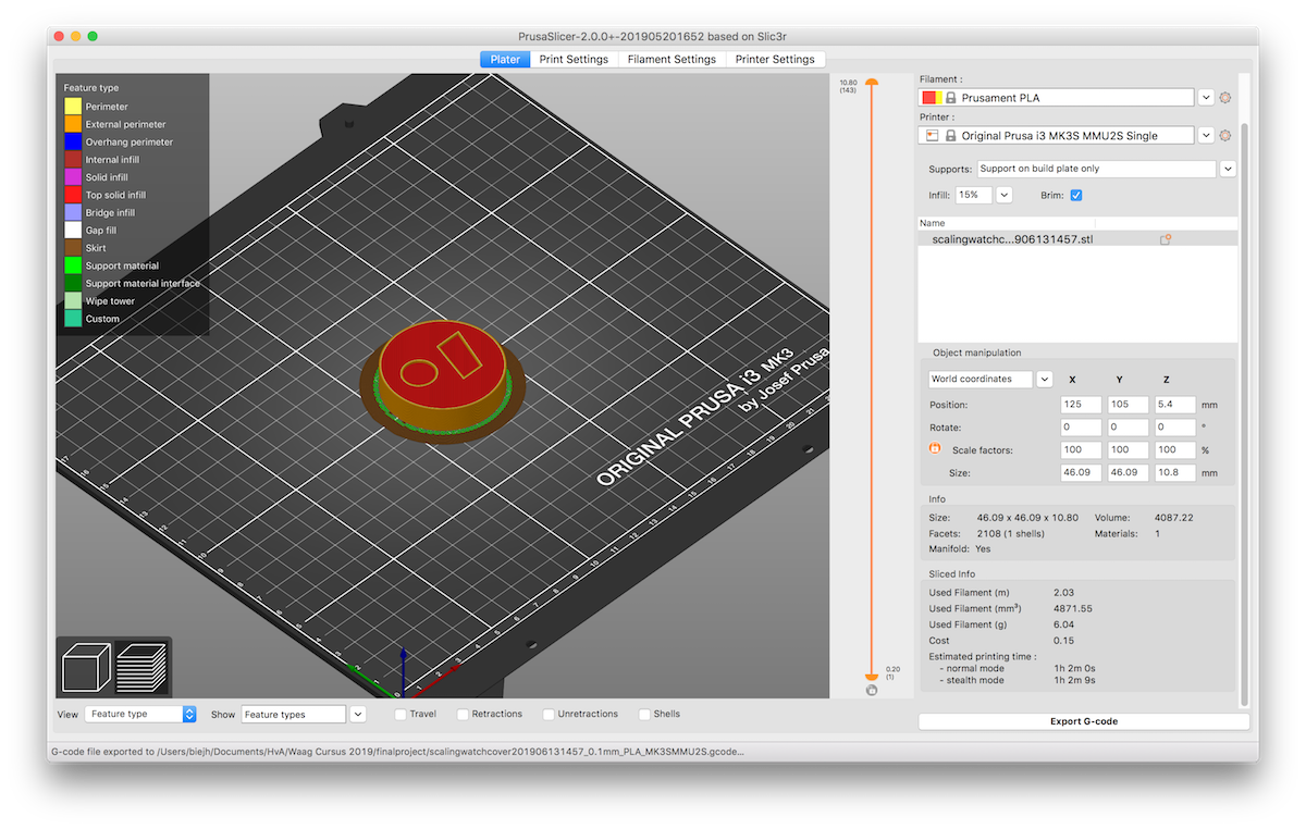
I exported the cover to an STL, and imported it in a new piece of software Prusa Slicer
Due to the Ultimaker not being available I had to switch to the Prusa i3 MK3S MMU2S.
This is the improved prusa MK3S, having a module that allowes to print with different filament at the same time!
I am not using different filament, I just want to quickly print this cover with one color.
But the new module does mean I have to use Prusa Slicer instead of Cura.
If provides pretty much the same settings options as Cura, only with the addition of the extra filament.
Also it has a beginner mode, making it easy for me to use.
I used the following settings:
- filament: Prusament PLA (red)
- printer: Prusa i3 MK3S MMU2S Single
- supports: supports on build plate only
- brim: yes
- infill 15%
I cleaned the board, loaded the filament in the first hole of the new module (the Prusa auto graps the filament, when you load in the hole), and started the print.
As with the Ultimaker the first print failed, now the brim was wrapping upwards.
I cancelled the job and started a new one again.
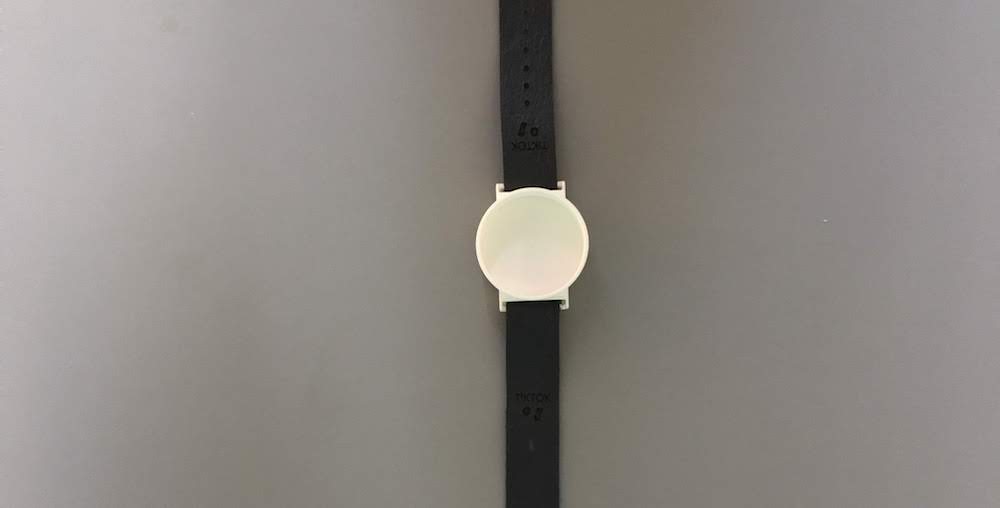
Now everything went fine and after an hour I had a big red cover, and trying to fit it on the watch case made a beautifull snapping sound!
Chosing a band type and size
Watch bands come in different shapes and sizes. I searched different watch band shops as https://www.dehorlogebandenspecialist.nl and https://www.horlogebanden.com/ for what available types and sizes are. I found there is a wide range of widths, starting at 8mm till 30mm. Most available bands are around 20mm and 24mm. So for now I will use a bind width of 24mm. A common, but big size, this allows me to easily try out different bands, and to keep my watch big. Further for quick prototyping I have velcro band and rubber bands that I can quickly fix to the watch body.
Connecting the band to the watch body
Then I could chose a band connector to the watch body. I know there are magnet connectors, slide in mechanism and pushpin axels.A simple Google search for watch band connectors shows allready many different types. I figured I should not try to invent the wheel on every part of the watch, so I went with the most common, the push pin. The push pin also comes in different sizes for different band widths. Since I use a band width of 24mm, my push pin should be at least 24mm. To be at the save side I want to use a pushpin of 26mm and let is rest a little deeper in my watch, since 3D prints arent always that stirdy. But time will tell if I really need to take this drastic measure.
Connecting the band to the watch body part 2
During the molding and casting week I decided the pushpin connector will probably be to fragile to use on a daily base.
Therefor I edited my 3D design to have slots where the watch band can go through.
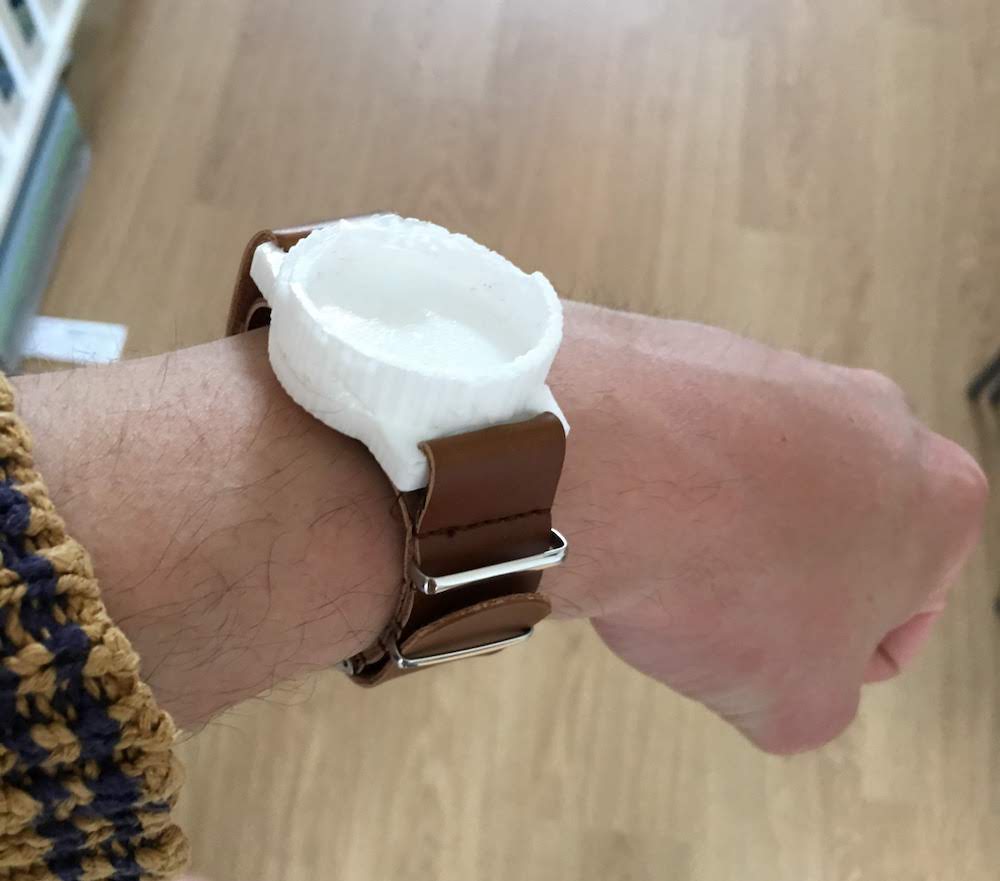
For the watchbands I ordered a leather and nylon band from China (Ali Express).
A few weeks after casting the mold the bands arrived, and I was able to test the result.
The slots fit perfectly with the ordered bands!
I need to do-over my mold to have a nice plastic mount, but with this first prototype I proved to myself this type of casing can work.
Creating a leather arm band
After discussing with Micky, I really wanted to create my own leather arm band.
I experimented with two small pieces of leather (thank you Micky) to create the TIKTOK arm band strap.
In Adobe Illustrator I designed the armband.
Looking at similar bands, I decided my dimensions.
Dimensions:
- lenght: 420 mm
- width: 22 mm
- holes length: 120 mm
- holes diameter/width: 2.2 mm
I created a rectangle of 420 by 22 mm, and modified the top corner with the Direct Selection tool (white pointer) to give it a round finish.
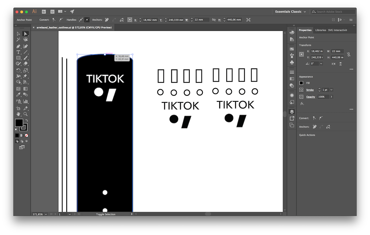
Next I drew some circles at one side for the holes for the pin of the arm band.
And I created a small rectangle at the other side of the rectangle for the position of the pin.
Last I though it would be nice to decorate the band with engravings of the TIKTOK logo, so I places a few logo’s on it.
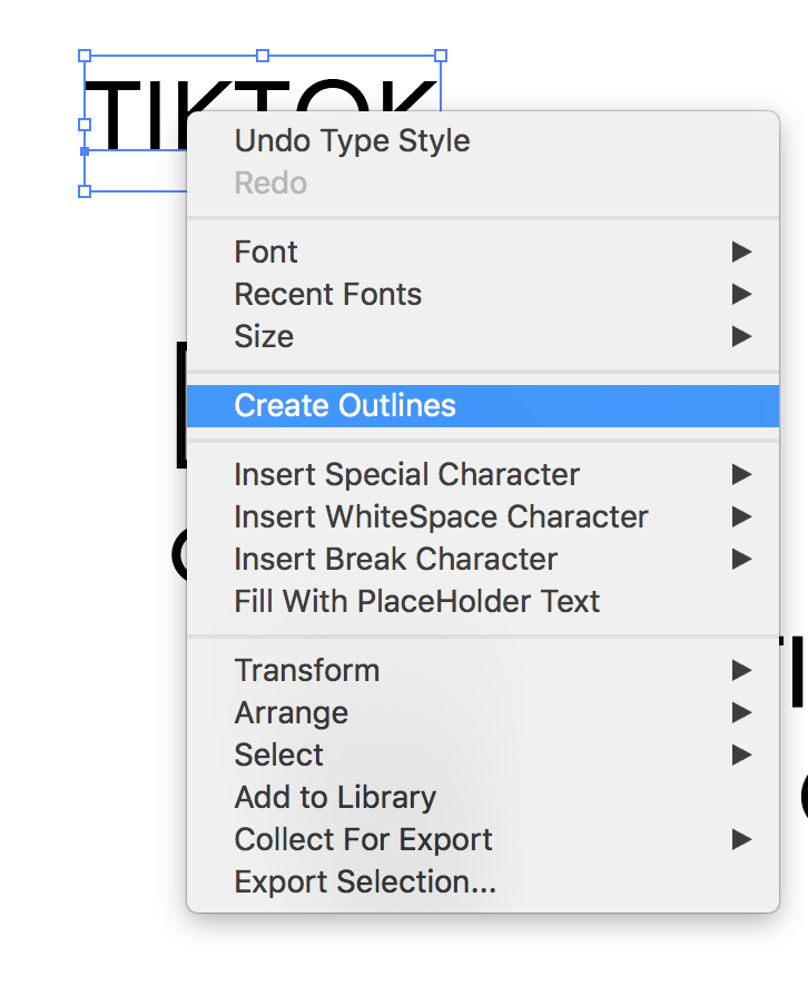
Note that when you want to laser cut text, you should first make vectors out of the text.
This also saves you hasle with transfering the design to another computer that does not have the font you use.
You can create a vector out of you text by right clicking your text and selecting the option, create outlines.
Next to the band, I created two small test designs, as you can also see in the picture.
I saved the Illustrator file as .ai and .dxf and copied them to the laser computer.
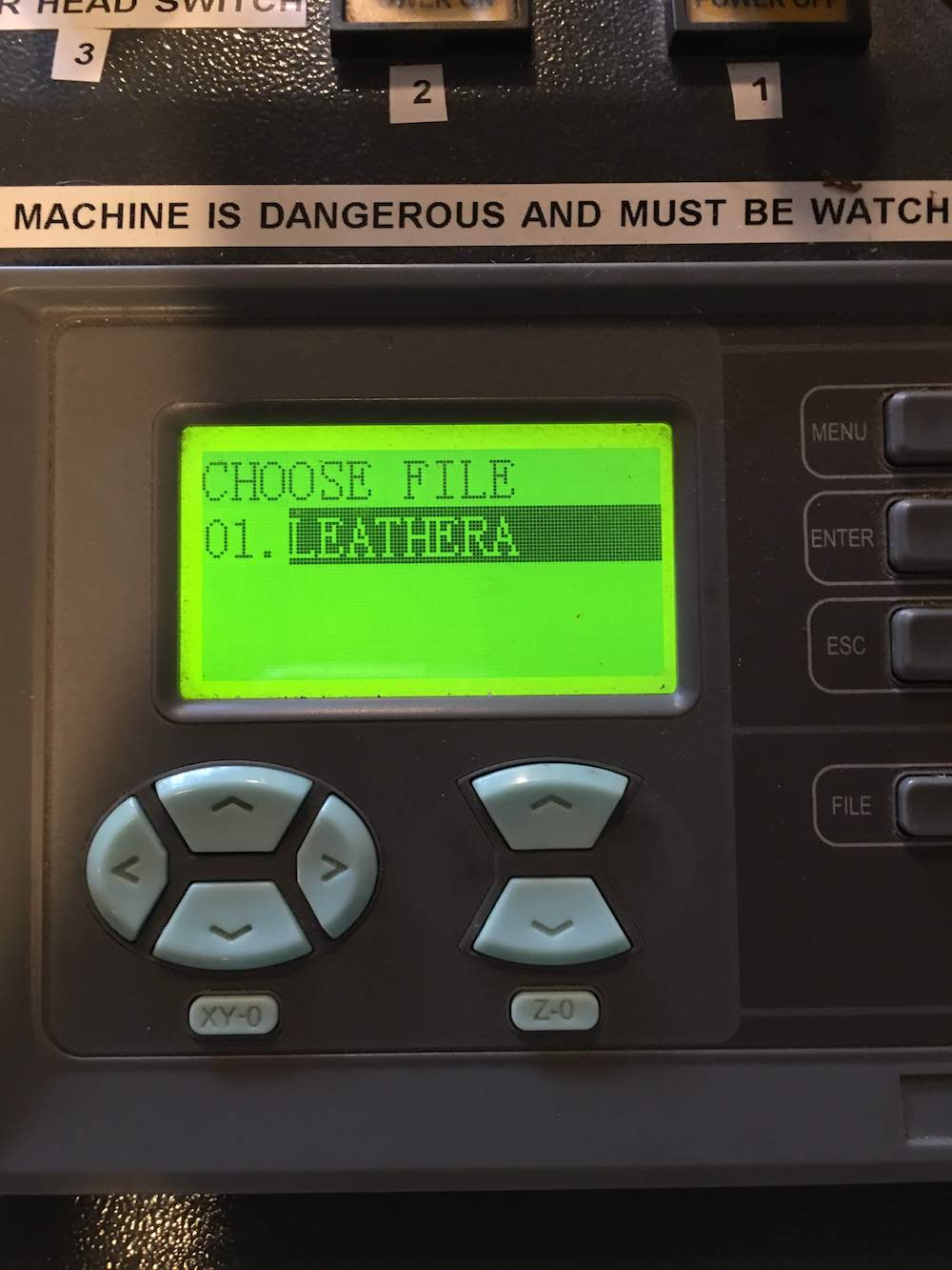
I took my laser manual I made in week 4 and started the laser software, and imported my design.
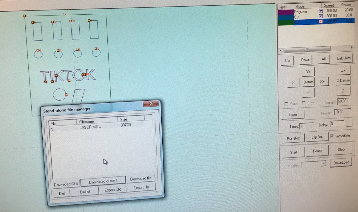
I selected the test cut piece and gave each item a color, and assigned to each color different settings.
Since I had not cut with leather before, I did not know the correct laser speed and power combination.
I had 5 circles, and for each one I selected a different cutting setting.
For example I started with:
- speed: 500, power: 10
- speed: 400, power: 10
- speed: 300, power: 10
- speed: 200, power: 10
- speed: 100, power: 10
I worked my way up to a higher power, and ended up selecting the cutting for speed: 300 and power 30.
Next I tried engraving with the same systematic approach, using the circles as a start.
After finding a nice engraved circle I tried to engrave the TIKTOK logo on the test piece.
I ended up selecting for the engraving:
- speed: 100, power: 20
Higher powers looked to burned for my tast, and higher speeds actually spoiled some engraving outside the desired area.
Last I tried the cutout settings around my engraving to cutout the test piece.
I found that my previous selected power and speed combination did cut through the material, but left some thin lines of fabric connected, giving a rough uneven look when releasing the piece from the leather.
After some trying with larger speeds, I concluded I had to use: - speed: 80, power: 50
I think this big difference between a larger square and a small circle has to do with the laser slowing down when reachting a corner, and needing a certain lenght to get up to speed. The circle was simply to small for the laser to actually reach the speed 300, but with the bigger square I was able to reach this speed.
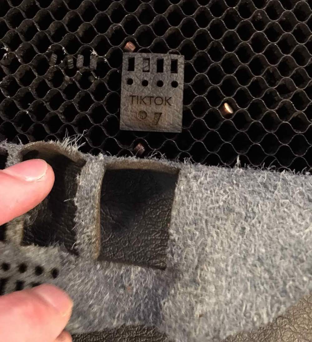
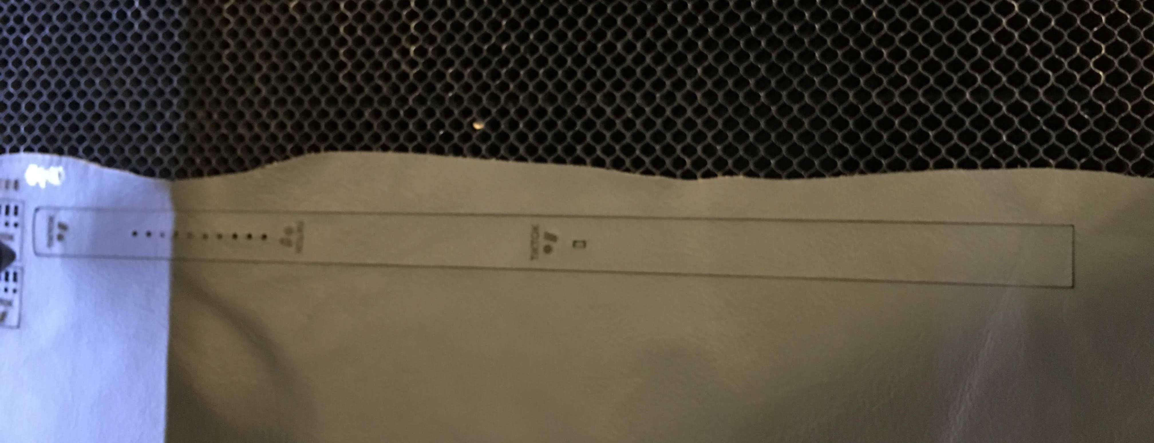
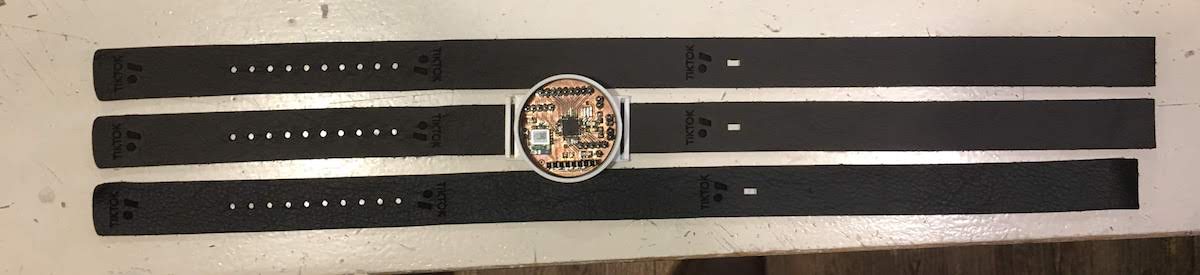
After finding the correct settings, which took me 1,5 hours I had to try on my actual design.
And… Succes! While I only needed one, I made 3 pieces to have some spares.
Time management.
I find this task a really nice example of my planning and triage, I had to keep my design simple to finish in time and almost finished exactly at the desired time. The leather band is a nice addition, but should take me to much time. Therefor I allowed me to take 5 hours to make the band.
- 2 hours design
- 2 hours cutting
- 1 hour finishing Also I would save this activity for the final days, since, if I could not find the time, I would make a sticker on the vynil cutter.
Thirsday I had to make my band on the laser cutter.
From 13:00 the device was reserved, so I had to finish it before that time.
I decided to take the time from 9.30 till 11.00 to design the band and test cuts in Illustrator,
and cut from 11:00 till 13:00 different band versions.
I finished my cut at 13.15.
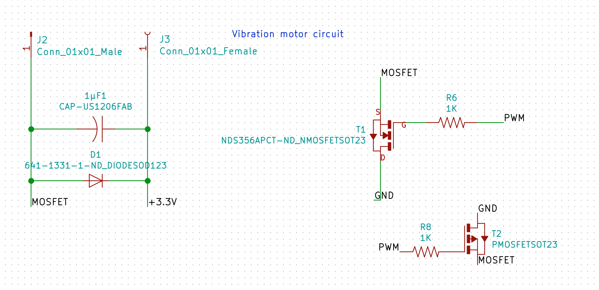
Vibration motor
Accelermeter, detecting taps
For my final board I use the MPU-6050 that I also used in the input week.
I wanted to use this board to detect taps.
The MPU-6050 does not have dedicated algorithms for detecting taps,
therefor we create a basic implementation on the Atmega using a threshold.
struct
{
  byte x: 1;
  int xIntensity;
  byte y: 1;
  int yIntensity;
  byte z: 1;
  int zIntensity;
  long last;
  long current;
} peak;

...

 AcX = abs(AcX);
    xNorm = (AcX * alpha) + (xNorm * (1 - alpha));
    AcX = abs(AcX - xNorm);
    xBuf[0] = xBuf[1];
    xBuf[1] = xBuf[2];
    xBuf[2] = AcX;
    if (xBuf[1] > TAP_MIN_THRESHOLD && xBuf[0]*TAP_SENSITIVITY_LEVEL < xBuf[1] && xBuf[1] > xBuf[2]*TAP_SENSITIVITY_LEVEL) {
      peak.x = 1;
      peak.xIntensity = xBuf[1];
      peak.current = previousRead;
    }

 ...

 //handle peaks
    if ((peak.x > 0 || peak.y > 0 || peak.z > 0) &&  peak.current - peak.last > 50) {
      //tap detected, send package over serial
      int intensity = (peak.xIntensity + peak.yIntensity + peak.zIntensity)/3/100;
      byte pattern[4];
      pattern[0] = intensity;//intensity
      pattern[1] = 0x0A;//duration
      if ((peak.current - peak.last) > 1000) {
              pattern[2] = 0x00;//max pause reached
      } else {
             pattern[2] = ((peak.current - peak.last) / 10); //pause
      }
      pattern[3] = 0xFF;//end

      bleSerial.write(pattern, 4);
      Serial.write(pattern, 4);

      peak.last = peak.current;

      vibrate(pattern);
    }
    //reset peak detection
    peak.x = 0;
    peak.xIntensity = 0;
    peak.y = 0;
    peak.yIntensity = 0;
    peak.z = 0;
    peak.zIntensity = 0;
The code loads a measurement of one axis, in this example the X axis.
Next it makes the value absolute, making sure we only work with positive values.
Then I normalise the value by substracting a running average (the alpha calculation) of the previous values.
Having a normalized X value I store it in a buffer with 2 previous measurements.
Then there is an if statement with peak detection above a threshold.
I compare the 2nd measurement with the first and 3rd measurement and see if it is 8 times higher (TAP_SENSITIVITY_LEVEL).
I determined this sensitivity level by tapping a lot of times on the device and next to the device.
Funny note, without this sensitivity threshold, I would many many peaks when the washing machine is on that is 5 meters away from the table!
So when the 2nd value is higher than the two other values, I count it as a peak, and store this in a struct.
After repeating these steps for the Y and Z axis I check the peak struct if a peak is found.
When found I calculate the average intensity by combining the 3 axis intensity values.
Then I create a package in a byte array containing my new package protocol:
- byte intensity
- byte duration, now default 0x0A (15, what translates to 15x10=150 ms)
- byte pause, either a value lower than 1000 ms or 0
- byte endbit 0xFF
I send this over the software serial to the BLE device, that sends it to the smartphone.
Also for debug I send it to my Serial
To notify the user, I also vibrate the pattern.
Last I reset the peak struct and start the loop over.
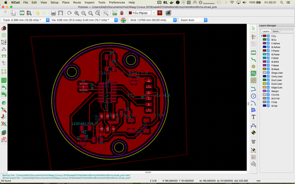
Board design
The board for my smarband builds on the knowledge I gained in the past weeks.
In week 5 I learned how to mill a board.
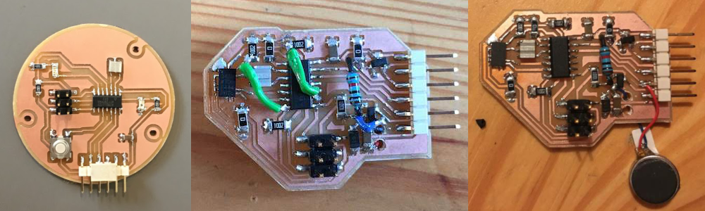
In week 7 , week 11 and week 12, I learned how to design a board with input and output devices.
Further in these weeks I evolved my design towards my smart band board design. With each new board I added functionality I needed for my final project.
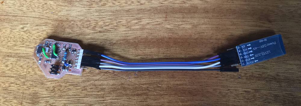
In week 14 I further explored the capabilities of my board by adding a Bluetooth module over Serial.
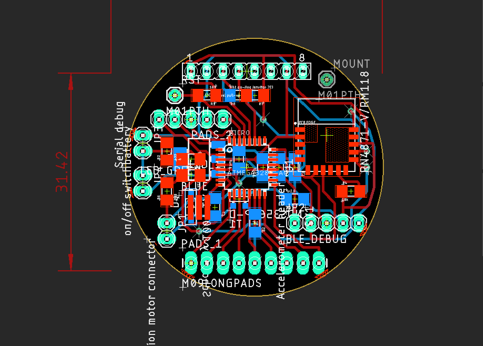
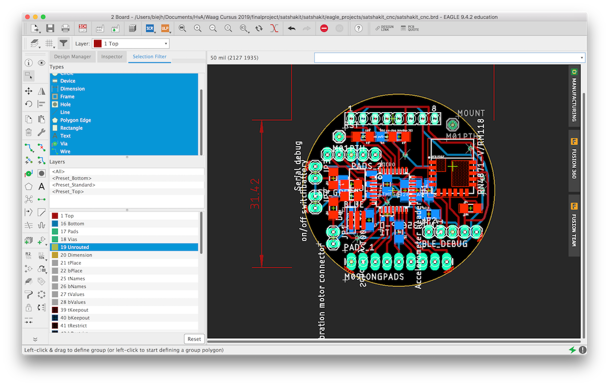
For my final board design I want to create a round board with a onboard Bluetooth module,
and expansion headers for an I2C accelerometer and serial communication.
Further I want it to have an on/off button, indicator LEDs, and the possibility for adding a battery module.
I want to make the board as small as possible.
I want to try to use both sides of the board as much as possible.
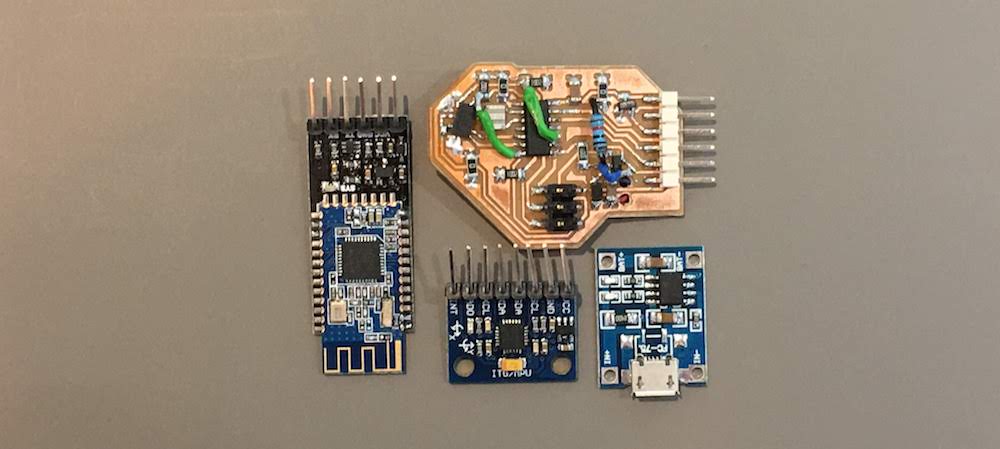
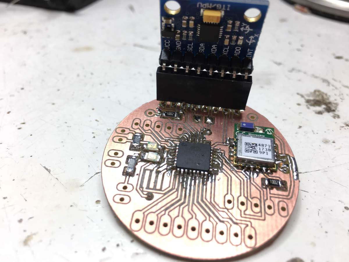
To get animpression of how the board will look I stacked all my modules on top of eachother
My first sketch I made in week 1 still resembles these requirements.
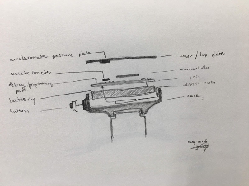
Now understanding better what components I am able to use, I could make my new board.
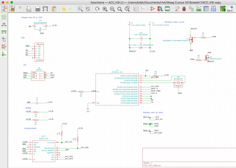
EAGLE
Having decided I want to make a double sided board, I also want to try out a new design tool.
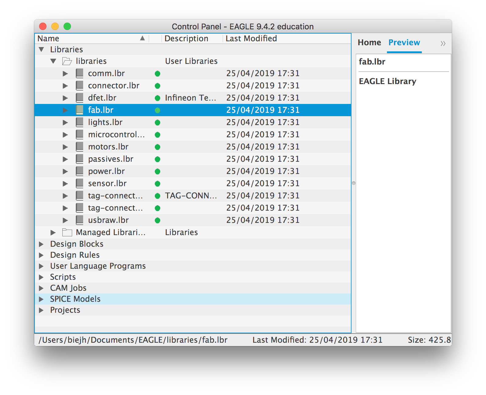
I installed Autodesk EAGLE and downloaded the FabAcademy components library.
You can import the files by copying them to “$HOME/Documents/EAGLE/libraries”.
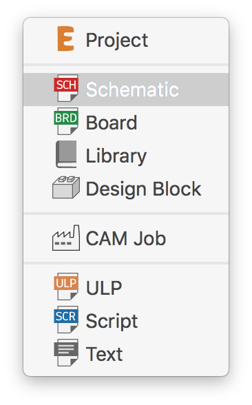
Next, use the “File->New” menu to start a new project and create a new schematic.
I started by downloading the Satshakit schematics.
The Satshakit is an Arduino Uno compatible board design, based on the Atmel Atmega 328p.
Defining components, connecting components, linking wires, all goes pretty much the same as in KiCad. The biggest difference is that in KiCad the options are on the right, in EAGLE on the left.
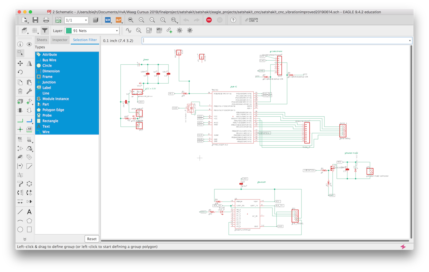
For some advice on how to use EAGLE, I searched around on the Fabacademy website and got some usefull tips from Jimena Galvesparedes. I modified the Satshakit by making it a 3.3V board, adding the RN4871 Bleutooth chip and the vibration motor circuit.
Bluetooth board RN4871
The Bluetooth board I will be using for my new board is the Microchip RN4871. It is a very tiny BLE 4.2 board, that allows me to further shrink my design.
The datasheet can be found here.
Although the board is part of the FabAcademy inventory, its schematic and footprint are not part of the design files.
They can be found for both KiCad as EAGLE on https://www.snapeda.com/parts/RN4871-V/RM118/Microchip/view-part/?ref=digikey.
Next up is connecting the board.
I connected the wires as specified in the datasheet.
Battery management
For connecting and charging the battery with my module I encountered some difficulties.
I received a battery charging module from Henk, but that does not provide an output to connect to your board.
Also I found that the charging module provided up to 4,7V, while this is to low for my voltage converter to 3.3V.
It really was a bummer that I could not use this board for my design and I had to drop onboard battery managment.
3.3V
During development, I discovered I used the wrong 3.3V converter.
The one I use only supports up to 100mA, while my board will use more due to the combination of the components and the vibration motor.
I switched the LM3480IM3-3.3/NOPBCT-ND for the ZLDO1117G33DICT-ND, that will support up to 1A.
Its datasheet can be found here
The biggest difference between the two components is the footprint: SOT223 instead of SOT23.
Next I noticed I did not included a capacitor from the raw voltage to the GND, thus I also included that.
MOSFET wrongly connected
Despite my efforts in week 12, I still connected my MOSFET wrong in my new board.
This resulted in a short circuit, the device kept drawing 2.5V and 1A, instead of 5V and about 0.06A.
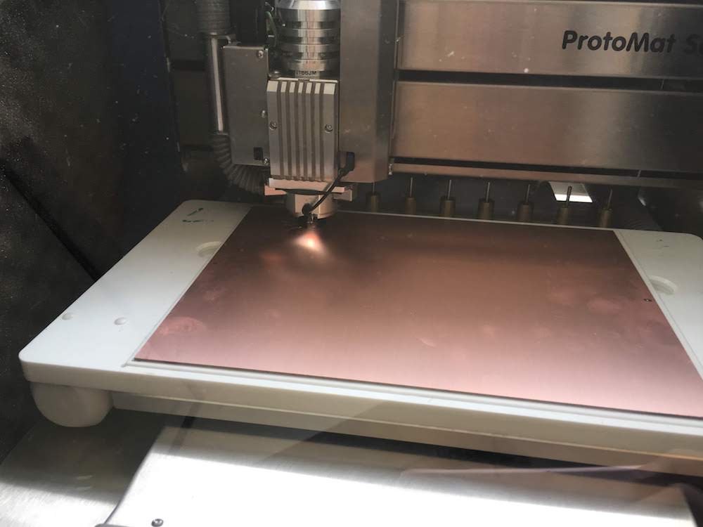
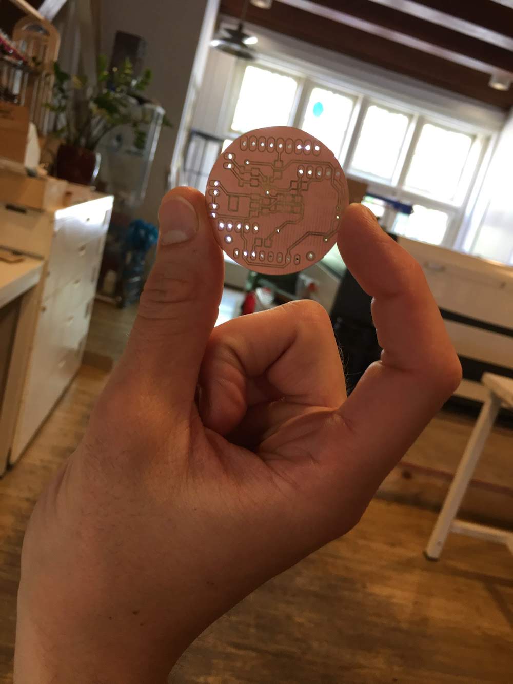
Milling the board
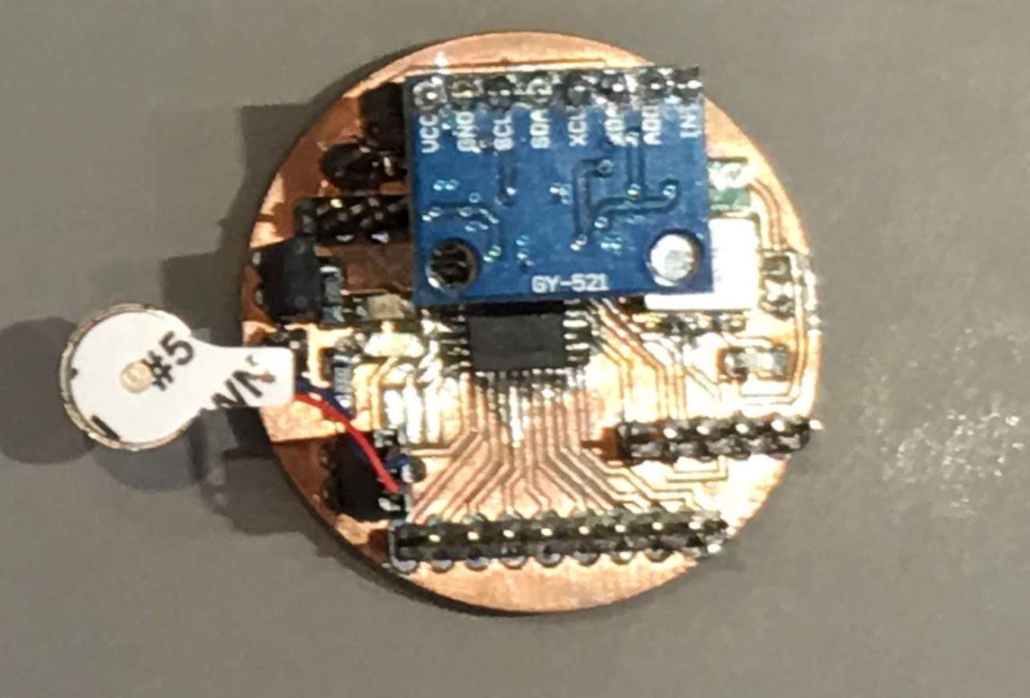
I milled my board on the Protomat S62, a PCB mill we have a the Amsterdam University of Applied Sciences Makerlab.
Since I had not used the device before, I decided to first explore its capabilities by making a test cut.
While doing this I learned how the device worked, and directly explained two of my students how the device works.
Honestly, most of the thinking was done for me, Fabacademy student and college Loes Bogers explored how to use the device and wrote a manual explaining all the steps. Thank you again Loes!
Burning the bootloader - Chip not responding
Arduino: 1.8.8 (Mac OS X), Board: "ATmega328 on a breadboard (8 MHz internal clock)"

/Applications/Arduino.app/Contents/Java/hardware/tools/avr/bin/avrdude -C/Applications/Arduino.app/Contents/Java/hardware/tools/avr/etc/avrdude.conf -v -patmega328p -cusbtiny -e -Ulock:w:0x3F:m -Uefuse:w:0x05:m -Uhfuse:w:0xDA:m -Ulfuse:w:0xE2:m

avrdude: Version 6.3-20171130
         Copyright (c) 2000-2005 Brian Dean, http://www.bdmicro.com/
         Copyright (c) 2007-2014 Joerg Wunsch

         System wide configuration file is "/Applications/Arduino.app/Contents/Java/hardware/tools/avr/etc/avrdude.conf"
         User configuration file is "/Users/biejh/.avrduderc"
         User configuration file does not exist or is not a regular file, skipping

         Using Port                    : usb
         Using Programmer              : usbtiny
avrdude: usbdev_open(): Found USBtinyISP, bus:device: 020:015
         AVR Part                      : ATmega328P
         Chip Erase delay              : 9000 us
         PAGEL                         : PD7
         BS2                           : PC2
         RESET disposition             : dedicated
         RETRY pulse                   : SCK
         serial program mode           : yes
         parallel program mode         : yes
         Timeout                       : 200
         StabDelay                     : 100
         CmdexeDelay                   : 25
         SyncLoops                     : 32
         ByteDelay                     : 0
         PollIndex                     : 3
         PollValue                     : 0x53
         Memory Detail                 :

                                  Block Poll               Page                       Polled
           Memory Type Mode Delay Size  Indx Paged  Size   Size #Pages MinW  MaxW   ReadBack
           ----------- ---- ----- ----- ---- ------ ------ ---- ------ ----- ----- ---------
           eeprom        65    20     4    0 no       1024    4      0  3600  3600 0xff 0xff
           flash         65     6   128    0 yes     32768  128    256  4500  4500 0xff 0xff
           lfuse          0     0     0    0 no          1    0      0  4500  4500 0x00 0x00
           hfuse          0     0     0    0 no          1    0      0  4500  4500 0x00 0x00
           efuse          0     0     0    0 no          1    0      0  4500  4500 0x00 0x00
           lock           0     0     0    0 no          1    0      0  4500  4500 0x00 0x00
           calibration    0     0     0    0 no          1    0      0     0     0 0x00 0x00
           signature      0     0     0    0 no          3    0      0     0     0 0x00 0x00

         Programmer Type : USBtiny
         Description     : USBtiny simple USB programmer, https://learn.adafruit.com/usbtinyisp
avrdude: programmer operation not supported

avrdude: Using SCK period of 10 usec
avrdude: AVR device initialized and ready to accept instructions

Reading | ################################################## | 100% 0.00s

avrdude: Device signature = 0x000000 (retrying)

Reading | ################################################## | 100% 0.00s

avrdude: Device signature = 0x000000 (retrying)

Error while burning bootloader.
Reading | ################################################## | 100% 0.00s

avrdude: Device signature = 0x000000
avrdude: Yikes!  Invalid device signature.
         Double check connections and try again, or use -F to override
         this check.


avrdude done.  Thank you.
This should be ATMEGA328P: 0x1E950F not 0x000000
I analyzed my traces and solder points.
Together with Henk I found 2 solder points that were connected to a copper area. This should not result in a short circuit, but still, unwanted.
Next I found that I had my MOSFET orientation wrong in the schematic.
Last I found that I had my pins reversed. In stead of having the SCK, MISO and MOSI on the left of my headers, they were on the right!
Afer rechecking with AVRDUDE, I could confirm that my chip was detected.
I burned the bootloader via the Arduino IDE:
/Applications/Arduino.app/Contents/Java/hardware/tools/avr/bin/avrdude -C/Applications/Arduino.app/Contents/Java/hardware/tools/avr/etc/avrdude.conf -v -patmega328p -cusbtiny -e -Ulock:w:0x3F:m -Uefuse:w:0x05:m -Uhfuse:w:0xDA:m -Ulfuse:w:0xE2:m

avrdude: Version 6.3-20171130
         Copyright (c) 2000-2005 Brian Dean, http://www.bdmicro.com/
         Copyright (c) 2007-2014 Joerg Wunsch

         System wide configuration file is "/Applications/Arduino.app/Contents/Java/hardware/tools/avr/etc/avrdude.conf"
         User configuration file is "/Users/biejh/.avrduderc"
         User configuration file does not exist or is not a regular file, skipping

         Using Port                    : usb
         Using Programmer              : usbtiny
avrdude: usbdev_open(): Found USBtinyISP, bus:device: 020:025
         AVR Part                      : ATmega328P
         Chip Erase delay              : 9000 us
         PAGEL                         : PD7
         BS2                           : PC2
         RESET disposition             : dedicated
         RETRY pulse                   : SCK
         serial program mode           : yes
         parallel program mode         : yes
         Timeout                       : 200
         StabDelay                     : 100
         CmdexeDelay                   : 25
         SyncLoops                     : 32
         ByteDelay                     : 0
         PollIndex                     : 3
         PollValue                     : 0x53
         Memory Detail                 :

                                  Block Poll               Page                       Polled
           Memory Type Mode Delay Size  Indx Paged  Size   Size #Pages MinW  MaxW   ReadBack
           ----------- ---- ----- ----- ---- ------ ------ ---- ------ ----- ----- ---------
           eeprom        65    20     4    0 no       1024    4      0  3600  3600 0xff 0xff
           flash         65     6   128    0 yes     32768  128    256  4500  4500 0xff 0xff
           lfuse          0     0     0    0 no          1    0      0  4500  4500 0x00 0x00
           hfuse          0     0     0    0 no          1    0      0  4500  4500 0x00 0x00
           efuse          0     0     0    0 no          1    0      0  4500  4500 0x00 0x00
           lock           0     0     0    0 no          1    0      0  4500  4500 0x00 0x00
           calibration    0     0     0    0 no          1    0      0     0     0 0x00 0x00
           signature      0     0     0    0 no          3    0      0     0     0 0x00 0x00

         Programmer Type : USBtiny
         Description     : USBtiny simple USB programmer, https://learn.adafruit.com/usbtinyisp
avrdude: programmer operation not supported

avrdude: Using SCK period of 10 usec
avrdude: AVR device initialized and ready to accept instructions

Reading | ################################################## | 100% 0.00s

avrdude: Device signature = 0x1e950f (probably m328p)
avrdude: erasing chip
avrdude: Using SCK period of 10 usec
avrdude: reading input file "0x3F"
avrdude: writing lock (1 bytes):

Writing | ################################################## | 100% 0.00s

avrdude: 1 bytes of lock written
avrdude: verifying lock memory against 0x3F:
avrdude: load data lock data from input file 0x3F:
avrdude: input file 0x3F contains 1 bytes
avrdude: reading on-chip lock data:

Reading | ################################################## | 100% 0.00s

avrdude: verifying ...
avrdude: 1 bytes of lock verified
avrdude: reading input file "0x05"
avrdude: writing efuse (1 bytes):

/Applications/Arduino.app/Contents/Java/hardware/tools/avr/bin/avrdude -C/Applications/Arduino.app/Contents/Java/hardware/tools/avr/etc/avrdude.conf -v -patmega328p -cusbtiny -Uflash:w:/Users/biejh/Documents/Arduino/hardware/breadboard/avr/bootloaders/atmega/ATmegaBOOT_168_atmega328_pro_8MHz.hex:i -Ulock:w:0x0F:m

avrdude: Version 6.3-20171130
         Copyright (c) 2000-2005 Brian Dean, http://www.bdmicro.com/
         Copyright (c) 2007-2014 Joerg Wunsch

         System wide configuration file is "/Applications/Arduino.app/Contents/Java/hardware/tools/avr/etc/avrdude.conf"
         User configuration file is "/Users/biejh/.avrduderc"
         User configuration file does not exist or is not a regular file, skipping

         Using Port                    : usb
         Using Programmer              : usbtiny
avrdude: usbdev_open(): Found USBtinyISP, bus:device: 020:025
         AVR Part                      : ATmega328P
         Chip Erase delay              : 9000 us
         PAGEL                         : PD7
         BS2                           : PC2
         RESET disposition             : dedicated
         RETRY pulse                   : SCK
         serial program mode           : yes
         parallel program mode         : yes
         Timeout                       : 200
         StabDelay                     : 100
         CmdexeDelay                   : 25
         SyncLoops                     : 32
         ByteDelay                     : 0
         PollIndex                     : 3
         PollValue                     : 0x53
         Memory Detail                 :

                                  Block Poll               Page                       Polled
           Memory Type Mode Delay Size  Indx Paged  Size   Size #Pages MinW  MaxW   ReadBack
           ----------- ---- ----- ----- ---- ------ ------ ---- ------ ----- ----- ---------
           eeprom        65    20     4    0 no       1024    4      0  3600  3600 0xff 0xff
           flash         65     6   128    0 yes     32768  128    256  4500  4500 0xff 0xff
           lfuse          0     0     0    0 no          1    0      0  4500  4500 0x00 0x00
           hfuse          0     0     0    0 no          1    0      0  4500  4500 0x00 0x00
           efuse          0     0     0    0 no          1    0      0  4500  4500 0x00 0x00
           lock           0     0     0    0 no          1    0      0  4500  4500 0x00 0x00
           calibration    0     0     0    0 no          1    0      0     0     0 0x00 0x00
           signature      0     0     0    0 no          3    0      0     0     0 0x00 0x00

         Programmer Type : USBtiny
         Description     : USBtiny simple USB programmer, https://learn.adafruit.com/usbtinyisp
avrdude: programmer operation not supported

avrdude: Using SCK period of 10 usec
Writing |  ***failed;
################################################## | 100% 0.03s

avrdude: 1 bytes of efuse written
avrdude: verifying efuse memory against 0x05:
avrdude: load data efuse data from input file 0x05:
avrdude: input file 0x05 contains 1 bytes
avrdude: reading on-chip efuse data:

Reading | ################################################## | 100% 0.00s

avrdude: verifying ...
avrdude: WARNING: invalid value for unused bits in fuse "efuse", should be set to 1 according to datasheet
This behaviour is deprecated and will result in an error in future version
You probably want to use 0xfd instead of 0x05 (double check with your datasheet first).
avrdude: 1 bytes of efuse verified
avrdude: reading input file "0xDA"
avrdude: writing hfuse (1 bytes):

Writing | ################################################## | 100% 0.01s

avrdude: 1 bytes of hfuse written
avrdude: verifying hfuse memory against 0xDA:
avrdude: load data hfuse data from input file 0xDA:
avrdude: input file 0xDA contains 1 bytes
avrdude: reading on-chip hfuse data:

Reading | ################################################## | 100% 0.00s

avrdude: verifying ...
avrdude: 1 bytes of hfuse verified
avrdude: reading input file "0xE2"
avrdude: writing lfuse (1 bytes):

Writing | ################################################## | 100% 0.01s

avrdude: 1 bytes of lfuse written
avrdude: verifying lfuse memory against 0xE2:
avrdude: load data lfuse data from input file 0xE2:
avrdude: input file 0xE2 contains 1 bytes
avrdude: reading on-chip lfuse data:

Reading | ################################################## | 100% 0.00s

avrdude: verifying ...
avrdude: 1 bytes of lfuse verified

avrdude done.  Thank you.

avrdude: AVR device initialized and ready to accept instructions

Reading | ################################################## | 100% 0.00s

avrdude: Device signature = 0x1e950f (probably m328p)
avrdude: NOTE: "flash" memory has been specified, an erase cycle will be performed
         To disable this feature, specify the -D option.
avrdude: erasing chip
avrdude: Using SCK period of 10 usec
avrdude: reading input file "/Users/biejh/Documents/Arduino/hardware/breadboard/avr/bootloaders/atmega/ATmegaBOOT_168_atmega328_pro_8MHz.hex"
avrdude: writing flash (32652 bytes):

Writing | ################################################## | 100% 0.00s

avrdude: 32652 bytes of flash written
avrdude: verifying flash memory against /Users/biejh/Documents/Arduino/hardware/breadboard/avr/bootloaders/atmega/ATmegaBOOT_168_atmega328_pro_8MHz.hex:
avrdude: load data flash data from input file /Users/biejh/Documents/Arduino/hardware/breadboard/avr/bootloaders/atmega/ATmegaBOOT_168_atmega328_pro_8MHz.hex:
avrdude: input file /Users/biejh/Documents/Arduino/hardware/breadboard/avr/bootloaders/atmega/ATmegaBOOT_168_atmega328_pro_8MHz.hex contains 32652 bytes
avrdude: reading on-chip flash data:

Reading | ################################################## | 100% 0.00s

avrdude: verifying ...
avrdude: 32652 bytes of flash verified
avrdude: reading input file "0x0F"
avrdude: writing lock (1 bytes):

Writing | ################################################## | 100% 0.01s

avrdude: 1 bytes of lock written
avrdude: verifying lock memory against 0x0F:
avrdude: load data lock data from input file 0x0F:
avrdude: input file 0x0F contains 1 bytes
avrdude: reading on-chip lock data:

Reading | ################################################## | 100% 0.00s

avrdude: verifying ...
avrdude: 1 bytes of lock verified

avrdude done.  Thank you.
After burning the bootloader, I tried to upload a Sketch via the FTDI controller. This resulted in upload errors and AVRDUDE telling me the device is out of sync.
To test if the Serial interface could be used at al, I uploaded my SerialTest sketch from week 12 via de SPI interface.
/Applications/Arduino.app/Contents/Java/arduino-builder -dump-prefs -logger=machine -hardware /Applications/Arduino.app/Contents/Java/hardware -hardware /Users/biejh/Library/Arduino15/packages -hardware /Users/biejh/Documents/Arduino/hardware -tools /Applications/Arduino.app/Contents/Java/tools-builder -tools /Applications/Arduino.app/Contents/Java/hardware/tools/avr -tools /Users/biejh/Library/Arduino15/packages -built-in-libraries /Applications/Arduino.app/Contents/Java/libraries -libraries /Users/biejh/Documents/Arduino/libraries -fqbn=breadboard:avr:atmega328bb -ide-version=10808 -build-path /var/folders/cf/kkh_r72x0jq1wqb573gs9w980000gs/T/arduino_build_346184 -warnings=none -build-cache /var/folders/cf/kkh_r72x0jq1wqb573gs9w980000gs/T/arduino_cache_943339 -prefs=build.warn_data_percentage=75 -prefs=runtime.tools.avrdude.path=/Applications/Arduino.app/Contents/Java/hardware/tools/avr -prefs=runtime.tools.avrdude-6.3.0-arduino14.path=/Applications/Arduino.app/Contents/Java/hardware/tools/avr -prefs=runtime.tools.arduinoOTA.path=/Applications/Arduino.app/Contents/Java/hardware/tools/avr -prefs=runtime.tools.arduinoOTA-1.2.1.path=/Applications/Arduino.app/Contents/Java/hardware/tools/avr -prefs=runtime.tools.avr-gcc.path=/Applications/Arduino.app/Contents/Java/hardware/tools/avr -prefs=runtime.tools.avr-gcc-5.4.0-atmel3.6.1-arduino2.path=/Applications/Arduino.app/Contents/Java/hardware/tools/avr -verbose /Users/biejh/Documents/HvA/Waag Cursus 2019/week16/SerialCommunicationTestFastResponse/SerialCommunicationTestFastResponse.ino
/Applications/Arduino.app/Contents/Java/arduino-builder -compile -logger=machine -hardware /Applications/Arduino.app/Contents/Java/hardware -hardware /Users/biejh/Library/Arduino15/packages -hardware /Users/biejh/Documents/Arduino/hardware -tools /Applications/Arduino.app/Contents/Java/tools-builder -tools /Applications/Arduino.app/Contents/Java/hardware/tools/avr -tools /Users/biejh/Library/Arduino15/packages -built-in-libraries /Applications/Arduino.app/Contents/Java/libraries -libraries /Users/biejh/Documents/Arduino/libraries -fqbn=breadboard:avr:atmega328bb -ide-version=10808 -build-path /var/folders/cf/kkh_r72x0jq1wqb573gs9w980000gs/T/arduino_build_346184 -warnings=none -build-cache /var/folders/cf/kkh_r72x0jq1wqb573gs9w980000gs/T/arduino_cache_943339 -prefs=build.warn_data_percentage=75 -prefs=runtime.tools.avrdude.path=/Applications/Arduino.app/Contents/Java/hardware/tools/avr -prefs=runtime.tools.avrdude-6.3.0-arduino14.path=/Applications/Arduino.app/Contents/Java/hardware/tools/avr -prefs=runtime.tools.arduinoOTA.path=/Applications/Arduino.app/Contents/Java/hardware/tools/avr -prefs=runtime.tools.arduinoOTA-1.2.1.path=/Applications/Arduino.app/Contents/Java/hardware/tools/avr -prefs=runtime.tools.avr-gcc.path=/Applications/Arduino.app/Contents/Java/hardware/tools/avr -prefs=runtime.tools.avr-gcc-5.4.0-atmel3.6.1-arduino2.path=/Applications/Arduino.app/Contents/Java/hardware/tools/avr -verbose /Users/biejh/Documents/HvA/Waag Cursus 2019/week16/SerialCommunicationTestFastResponse/SerialCommunicationTestFastResponse.ino
Using board 'atmega328bb' from platform in folder: /Users/biejh/Documents/Arduino/hardware/breadboard/avr
Using core 'arduino' from platform in folder: /Applications/Arduino.app/Contents/Java/hardware/arduino/avr
Warning: Board breadboard:avr:atmega328bb doesn't define a 'build.board' preference. Auto-set to: AVR_ATMEGA328BB
Detecting libraries used...
/Applications/Arduino.app/Contents/Java/hardware/tools/avr/bin/avr-g++ -c -g -Os -w -std=gnu++11 -fpermissive -fno-exceptions -ffunction-sections -fdata-sections -fno-threadsafe-statics -Wno-error=narrowing -flto -w -x c++ -E -CC -mmcu=atmega328p -DF_CPU=8000000L -DARDUINO=10808 -DARDUINO_AVR_ATMEGA328BB -DARDUINO_ARCH_AVR -I/Applications/Arduino.app/Contents/Java/hardware/arduino/avr/cores/arduino -I/Applications/Arduino.app/Contents/Java/hardware/arduino/avr/variants/standard /var/folders/cf/kkh_r72x0jq1wqb573gs9w980000gs/T/arduino_build_346184/sketch/SerialCommunicationTestFastResponse.ino.cpp -o /dev/null
/Applications/Arduino.app/Contents/Java/hardware/tools/avr/bin/avr-g++ -c -g -Os -w -std=gnu++11 -fpermissive -fno-exceptions -ffunction-sections -fdata-sections -fno-threadsafe-statics -Wno-error=narrowing -flto -w -x c++ -E -CC -mmcu=atmega328p -DF_CPU=8000000L -DARDUINO=10808 -DARDUINO_AVR_ATMEGA328BB -DARDUINO_ARCH_AVR -I/Applications/Arduino.app/Contents/Java/hardware/arduino/avr/cores/arduino -I/Applications/Arduino.app/Contents/Java/hardware/arduino/avr/variants/standard -I/Applications/Arduino.app/Contents/Java/hardware/arduino/avr/libraries/SoftwareSerial/src /var/folders/cf/kkh_r72x0jq1wqb573gs9w980000gs/T/arduino_build_346184/sketch/SerialCommunicationTestFastResponse.ino.cpp -o /dev/null
Using cached library dependencies for file: /Applications/Arduino.app/Contents/Java/hardware/arduino/avr/libraries/SoftwareSerial/src/SoftwareSerial.cpp
Generating function prototypes...
/Applications/Arduino.app/Contents/Java/hardware/tools/avr/bin/avr-g++ -c -g -Os -w -std=gnu++11 -fpermissive -fno-exceptions -ffunction-sections -fdata-sections -fno-threadsafe-statics -Wno-error=narrowing -flto -w -x c++ -E -CC -mmcu=atmega328p -DF_CPU=8000000L -DARDUINO=10808 -DARDUINO_AVR_ATMEGA328BB -DARDUINO_ARCH_AVR -I/Applications/Arduino.app/Contents/Java/hardware/arduino/avr/cores/arduino -I/Applications/Arduino.app/Contents/Java/hardware/arduino/avr/variants/standard -I/Applications/Arduino.app/Contents/Java/hardware/arduino/avr/libraries/SoftwareSerial/src /var/folders/cf/kkh_r72x0jq1wqb573gs9w980000gs/T/arduino_build_346184/sketch/SerialCommunicationTestFastResponse.ino.cpp -o /var/folders/cf/kkh_r72x0jq1wqb573gs9w980000gs/T/arduino_build_346184/preproc/ctags_target_for_gcc_minus_e.cpp
/Applications/Arduino.app/Contents/Java/tools-builder/ctags/5.8-arduino11/ctags -u --language-force=c++ -f - --c++-kinds=svpf --fields=KSTtzns --line-directives /var/folders/cf/kkh_r72x0jq1wqb573gs9w980000gs/T/arduino_build_346184/preproc/ctags_target_for_gcc_minus_e.cpp
Compiling sketch...
/Applications/Arduino.app/Contents/Java/hardware/tools/avr/bin/avr-g++ -c -g -Os -w -std=gnu++11 -fpermissive -fno-exceptions -ffunction-sections -fdata-sections -fno-threadsafe-statics -Wno-error=narrowing -MMD -flto -mmcu=atmega328p -DF_CPU=8000000L -DARDUINO=10808 -DARDUINO_AVR_ATMEGA328BB -DARDUINO_ARCH_AVR -I/Applications/Arduino.app/Contents/Java/hardware/arduino/avr/cores/arduino -I/Applications/Arduino.app/Contents/Java/hardware/arduino/avr/variants/standard -I/Applications/Arduino.app/Contents/Java/hardware/arduino/avr/libraries/SoftwareSerial/src /var/folders/cf/kkh_r72x0jq1wqb573gs9w980000gs/T/arduino_build_346184/sketch/SerialCommunicationTestFastResponse.ino.cpp -o /var/folders/cf/kkh_r72x0jq1wqb573gs9w980000gs/T/arduino_build_346184/sketch/SerialCommunicationTestFastResponse.ino.cpp.o
Compiling libraries...
Compiling library "SoftwareSerial"
Using previously compiled file: /var/folders/cf/kkh_r72x0jq1wqb573gs9w980000gs/T/arduino_build_346184/libraries/SoftwareSerial/SoftwareSerial.cpp.o
Compiling core...
Using precompiled core: /var/folders/cf/kkh_r72x0jq1wqb573gs9w980000gs/T/arduino_cache_943339/core/core_breadboard_avr_atmega328bb_51f02b7210b938436b779d1c032618e1.a
Linking everything together...
/Applications/Arduino.app/Contents/Java/hardware/tools/avr/bin/avr-gcc -w -Os -g -flto -fuse-linker-plugin -Wl,--gc-sections -mmcu=atmega328p -o /var/folders/cf/kkh_r72x0jq1wqb573gs9w980000gs/T/arduino_build_346184/SerialCommunicationTestFastResponse.ino.elf /var/folders/cf/kkh_r72x0jq1wqb573gs9w980000gs/T/arduino_build_346184/sketch/SerialCommunicationTestFastResponse.ino.cpp.o /var/folders/cf/kkh_r72x0jq1wqb573gs9w980000gs/T/arduino_build_346184/libraries/SoftwareSerial/SoftwareSerial.cpp.o /var/folders/cf/kkh_r72x0jq1wqb573gs9w980000gs/T/arduino_build_346184/arduino_cache_943339/core/core_breadboard_avr_atmega328bb_51f02b7210b938436b779d1c032618e1.a -L/var/folders/cf/kkh_r72x0jq1wqb573gs9w980000gs/T/arduino_build_346184 -lm
/Applications/Arduino.app/Contents/Java/hardware/tools/avr/bin/avr-objcopy -O ihex -j .eeprom --set-section-flags=.eeprom=alloc,load --no-change-warnings --change-section-lma .eeprom=0 /var/folders/cf/kkh_r72x0jq1wqb573gs9w980000gs/T/arduino_build_346184/SerialCommunicationTestFastResponse.ino.elf /var/folders/cf/kkh_r72x0jq1wqb573gs9w980000gs/T/arduino_build_346184/SerialCommunicationTestFastResponse.ino.eep
/Applications/Arduino.app/Contents/Java/hardware/tools/avr/bin/avr-objcopy -O ihex -R .eeprom /var/folders/cf/kkh_r72x0jq1wqb573gs9w980000gs/T/arduino_build_346184/SerialCommunicationTestFastResponse.ino.elf /var/folders/cf/kkh_r72x0jq1wqb573gs9w980000gs/T/arduino_build_346184/SerialCommunicationTestFastResponse.ino.hex
Using library SoftwareSerial at version 1.0 in folder: /Applications/Arduino.app/Contents/Java/hardware/arduino/avr/libraries/SoftwareSerial
/Applications/Arduino.app/Contents/Java/hardware/tools/avr/bin/avr-size -A /var/folders/cf/kkh_r72x0jq1wqb573gs9w980000gs/T/arduino_build_346184/SerialCommunicationTestFastResponse.ino.elf
Sketch uses 2790 bytes (9%) of program storage space. Maximum is 30720 bytes.
Global variables use 132 bytes of dynamic memory.
/Applications/Arduino.app/Contents/Java/hardware/tools/avr/bin/avrdude -C/Applications/Arduino.app/Contents/Java/hardware/tools/avr/etc/avrdude.conf -v -patmega328p -cusbtiny -Uflash:w:/var/folders/cf/kkh_r72x0jq1wqb573gs9w980000gs/T/arduino_build_346184/SerialCommunicationTestFastResponse.ino.hex:i

avrdude: Version 6.3-20171130
         Copyright (c) 2000-2005 Brian Dean, http://www.bdmicro.com/
         Copyright (c) 2007-2014 Joerg Wunsch

         System wide configuration file is "/Applications/Arduino.app/Contents/Java/hardware/tools/avr/etc/avrdude.conf"
         User configuration file is "/Users/biejh/.avrduderc"
         User configuration file does not exist or is not a regular file, skipping

         Using Port                    : usb
         Using Programmer              : usbtiny
avrdude: usbdev_open(): Found USBtinyISP, bus:device: 020:014
         AVR Part                      : ATmega328P
         Chip Erase delay              : 9000 us
         PAGEL                         : PD7
         BS2                           : PC2
         RESET disposition             : dedicated
         RETRY pulse                   : SCK
         serial program mode           : yes
         parallel program mode         : yes
         Timeout                       : 200
         StabDelay                     : 100
         CmdexeDelay                   : 25
         SyncLoops                     : 32
         ByteDelay                     : 0
         PollIndex                     : 3
         PollValue                     : 0x53
         Memory Detail                 :

                                  Block Poll               Page                       Polled
           Memory Type Mode Delay Size  Indx Paged  Size   Size #Pages MinW  MaxW   ReadBack
           ----------- ---- ----- ----- ---- ------ ------ ---- ------ ----- ----- ---------
           eeprom        65    20     4    0 no       1024    4      0  3600  3600 0xff 0xff
           flash         65     6   128    0 yes     32768  128    256  4500  4500 0xff 0xff
           lfuse          0     0     0    0 no          1    0      0  4500  4500 0x00 0x00
           hfuse          0     0     0    0 no          1    0      0  4500  4500 0x00 0x00
           efuse          0     0     0    0 no          1    0      0  4500  4500 0x00 0x00
           lock           0     0     0    0 no          1    0      0  4500  4500 0x00 0x00
           calibration    0     0     0    0 no          1    0      0     0     0 0x00 0x00
           signature      0     0     0    0 no          3    0      0     0     0 0x00 0x00

         Programmer Type : USBtiny
         Description     : USBtiny simple USB programmer, https://learn.adafruit.com/usbtinyisp
avrdude: programmer operation not supported

avrdude: Using SCK period of 10 usec
avrdude: AVR device initialized and ready to accept instructions

Reading | ################################################## | 100% 0.00s

avrdude: Device signature = 0x1e950f (probably m328p)
avrdude: NOTE: "flash" memory has been specified, an erase cycle will be performed
         To disable this feature, specify the -D option.
avrdude: erasing chip
avrdude: Using SCK period of 10 usec
avrdude: reading input file "/var/folders/cf/kkh_r72x0jq1wqb573gs9w980000gs/T/arduino_build_346184/SerialCommunicationTestFastResponse.ino.hex"
avrdude: writing flash (2790 bytes):

Writing | ################################################## | 100% 3.34s

avrdude: 2790 bytes of flash written
avrdude: verifying flash memory against /var/folders/cf/kkh_r72x0jq1wqb573gs9w980000gs/T/arduino_build_346184/SerialCommunicationTestFastResponse.ino.hex:
avrdude: load data flash data from input file /var/folders/cf/kkh_r72x0jq1wqb573gs9w980000gs/T/arduino_build_346184/SerialCommunicationTestFastResponse.ino.hex:
avrdude: input file /var/folders/cf/kkh_r72x0jq1wqb573gs9w980000gs/T/arduino_build_346184/SerialCommunicationTestFastResponse.ino.hex contains 2790 bytes
avrdude: reading on-chip flash data:

Reading | ################################################## | 100% 2.24s

avrdude: verifying ...
avrdude: 2790 bytes of flash verified

avrdude done.  Thank you.
Now when testing the serial, everything worked, and I knew I had a working chip that I could program va SPI and debug over Serial.
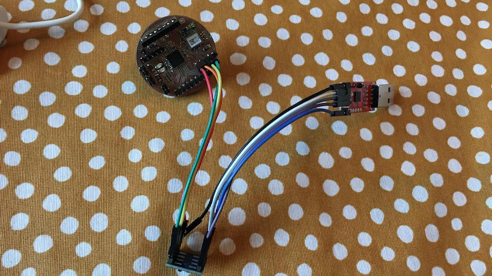
Testing the Bluetooth board
Next up was the testing of the Bluetooth board.
My new board had special debug headers for the Bluetooth board, that I connected my FTDI controller to.
The board uses 3.3v, so I used a 5v to 3.3v converter to convert the VCC and TX pin of my FTDI controller.
I download the “RN4870/71 Bluetooth® Low Energy Module User’s Guide” and looked up the specific serial commands I need.
From the manual on page 12 I learned the device is by default a pipe directly transfering received data:
The RN4870/71 operates in two modes: Data mode (default) and Command mode. When RN4870/71 is connected to another BLE device and is in Data mode, the RN4870/71 acts as a data pipe: any serial data sent into RN4870/71 UART is trans- ferred to the connected peer device via Transparent UART Bluetooth service. When data is received from the peer device over the air via Transparent UART connection, this data outputs directly to UART.
On page 13, we see we can connect over serial using the following settings:
- Baud Rate: 115200
- Data Bits: 8
- Parity: None
- Stop Bits: 1
- Flow Control: Disabled
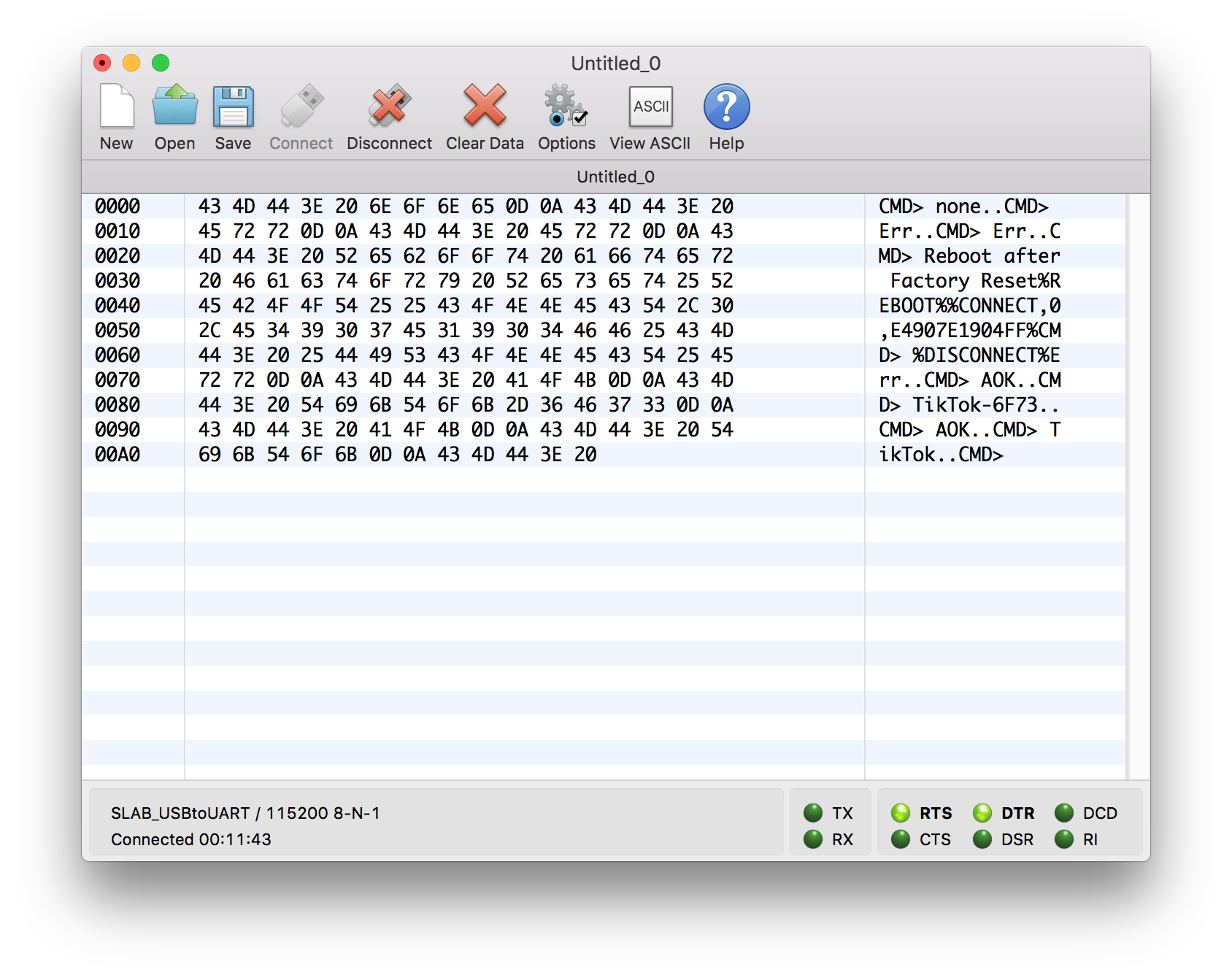
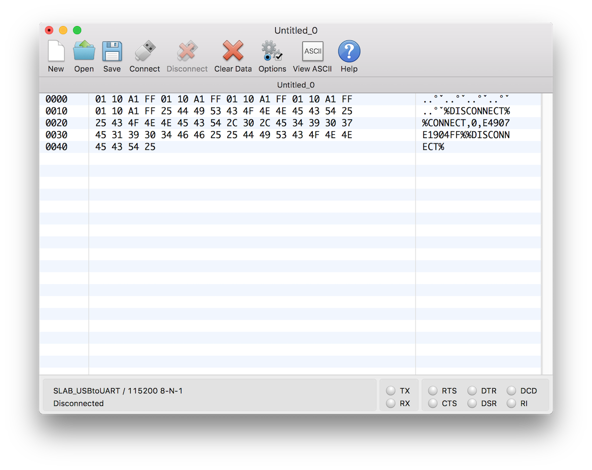
I copied these settings to CoolTerm and directly got response when starting the device.
In the manual on page 15, we find that commands can be send in ASCII and always end with a CR (Cariage Return). To start communicating with the chip over serial you first need to activate “Command mode”. This can be done by sending:
$$$
When the device is in Command Mode it sends the response:
CMD>
Next with the SN command, I set the name to “TikTok”:
SN,TikTok
When askin the name with the GN command, I received “TikTok” as name.
With the D command we get some default settings information of the device:
CMD> BTA=D88039FA6F73
Name=TikTok
Connected=no
Authen=2
Features=0000
Services=00
With V we get the firmware version on the device
CMD> RN4871 V1.18.3 4/14/2016 (c)Microchip Technology Inc
At the website of Microchip, we find the latest firmware ie 1.30. I am a bit behind. Still we have enough basic functionality to continue without updating the firmware.
Android app
Inweek 14 I added a Bluetooth board to my microcontroller and was able to communicate with my iPhone and a Serial Bluetooth app with the microcontroller.
In week 16 I expanded this functionality by creating a custom app.
It is based on the BLEArduino app, but I had to expand its functionality to be able to send and receive data with my board new board.
This because in week 16 I used the HM-10 module and I now use the Microchip RN4871. Also I did not refined the user interface.
Bluetooth app enhauncements
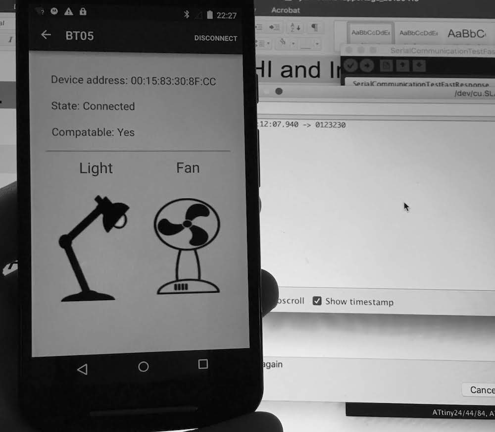
I tested connection with the module, by downloading the Microchip Bluetooth Smart Discovery app
With this app I could not connect to the device.
I tried to connect with the device via my own Android app created in week16, and this worked! I directly got a connection and saw the connect and disconnect messages in the Cool Term app.
However I was not able to send and receive data from my app.
To further get my apps working I read on page 59 of the manual, how to get the Transparent UART functionality for BLE working.
I had to type the following commands over serial:
$$$
+
SS,C0
R,1
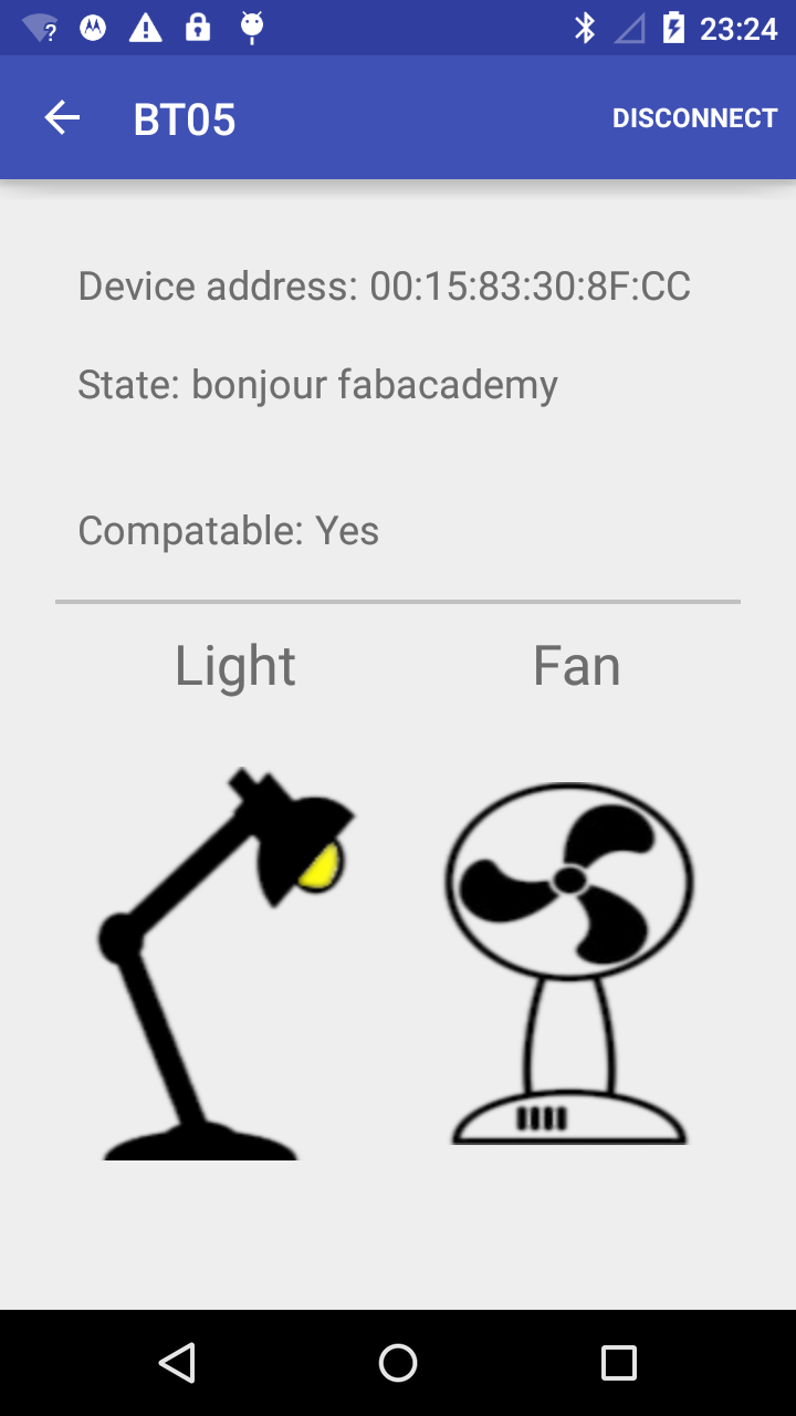
Now I could see the GATT services, communicate and properly connect with most apps.
Only not my Android app, this was because it was only looking for the GATTs from the HM10 device, not the RN4871.
I looked up the specific UUID’s on page 65 in the manual and added them to my Android app.
    public static String RF4871_RX_TX = "49535343-FE7D-4AE5-8FA9-9FAFD205E455"; //the service
    public static String RF4871_TX = "49535343-1E4D-4BD9-BA61-23C647249616"; // the characteristics
    public static String RF4871_RX = "49535343-8841-43F4-A8D4-ECBE34729BB3"; // the characteristics
Fail with setting the UUID HEX codes for the new GATT
At first my changes did not had any effect.
Only after a few hours tweeking and trying out different combinations, I found that somehow the HEX codes in Android are case sensitive!
This is clearly a bug, HEX codes should be either all upper case or it should not matter.
After setting the HEX values to lower case sending of the data worked.
public static String RF4871_RX_TX = "49535343-FE7D-4AE5-8FA9-9FAFD205E455".toLowerCase();
Fail, not able to receive values
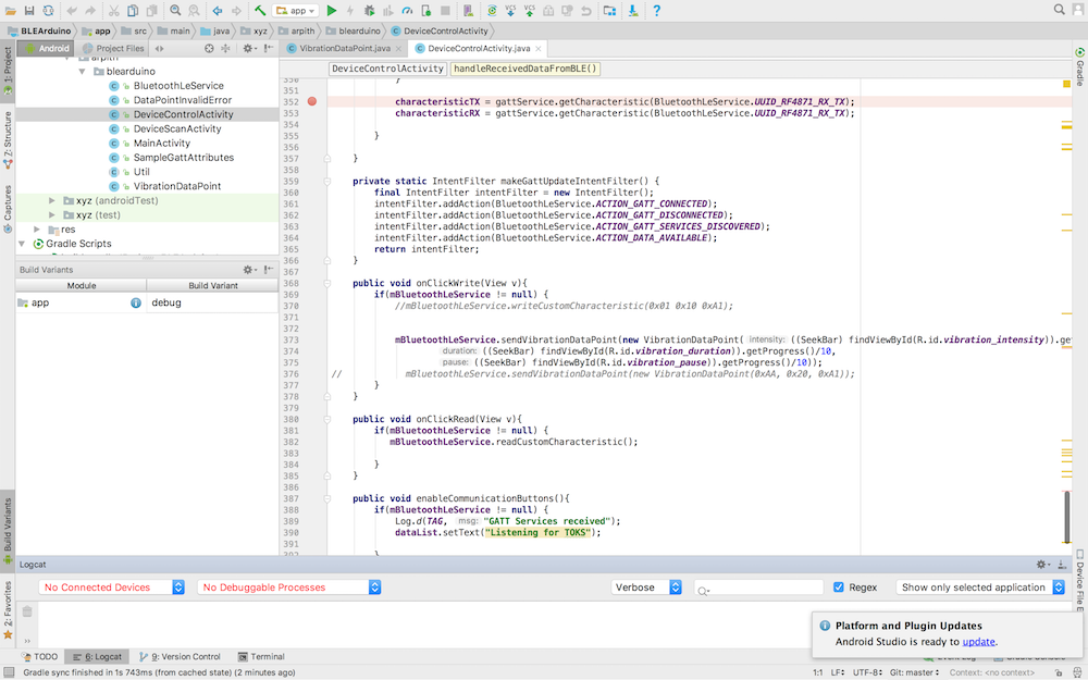
Next, I was not able to receive values from the BLE chip on my app.
As I looked at the received services, and read about the service, I thought that maybe I used the wrong approach in Android.
I found this great simple tutorial on all about circuits and implemented it in my BLE app.
But, when asking the Android Bluetooth service if data was available, I kept receiving the message that this GATT was not available.
When I looked at the logs, I noticed I sometimes tried to ask to fast for this data, so before the Bleutooth service was finished with connecting and gathering the available services.
Since the Bleutooth service tells us when it is finished gathering BLE services, I used that listener to tell me when I could start gathering data.
    ...
    } else if (BluetoothLeService.ACTION_GATT_SERVICES_DISCOVERED.equals(action)) {
        //enable communication buttons.
        enableCommunicationButtons();
    }

    ...

 	public void enableCommunicationButtons(){
		 if(mBluetoothLeService != null) {
		     Log.d(TAG, "GATT Services received, you can start listening");
		 }
	 }
Still the receiving of the data gave no result, but at least I now had no errors.
I went back to my old code for my MH10 BLE device and looked at how I received data via that device.
I did it not by directly requesting available data, but by setting a notification.
Both approaches should work according to the documentation in the Microchip R4871 manual, but I thought that maybe it is an Android thing why it does not work via the new approach.
I modified the code to activate the notification. And I started receiving the values.
    public void readCustomCharacteristic() {
        if (mBluetoothAdapter == null || mBluetoothGatt == null) {
            Log.w(TAG, "BluetoothAdapter not initialized");
            return;
        }
        /*check if the service is available on the device*/
        BluetoothGattService mCustomService = mBluetoothGatt.getService(UUID.fromString(SampleGattAttributes.RF4871_RX_TX));
        if(mCustomService == null){
            Log.w(TAG, "Custom BLE Service not found");
            return;
        }
        /*get the read characteristic from the service*/
        BluetoothGattCharacteristic mReadCharacteristic = mCustomService.getCharacteristic(UUID.fromString(SampleGattAttributes.RF4871_TX));
        if(mBluetoothGatt.readCharacteristic(mReadCharacteristic) == false){
            Log.w(TAG, "Failed to read characteristic, setting notification");
            setCharacteristicNotification(mReadCharacteristic, true);
        }
    }
    /**
     * Enables or disables notification on a give characteristic.
     *
     * @param characteristic Characteristic to act on.
     * @param enabled If true, enable notification.  False otherwise.
     */
    public void setCharacteristicNotification(BluetoothGattCharacteristic characteristic,
                                              boolean enabled) {
        if (mBluetoothAdapter == null || mBluetoothGatt == null) {
            Log.w(TAG, "BluetoothAdapter not initialized");
            return;
        }
        mBluetoothGatt.setCharacteristicNotification(characteristic, enabled);

        if ( UUID.fromString(SampleGattAttributes.RF4871_TX).equals(characteristic.getUuid())) {
            BluetoothGattDescriptor descriptor = characteristic.getDescriptor(
                    UUID.fromString(SampleGattAttributes.CLIENT_CHARACTERISTIC_CONFIG));
            descriptor.setValue(BluetoothGattDescriptor.ENABLE_NOTIFICATION_VALUE);
            mBluetoothGatt.writeDescriptor(descriptor);
        }
    }
Note that I kept the CLIENT_CHARACTERISTIC_CONFIG. This is a special descriptor telling the Bluetooth service the BLE service is a custom service, not defined in the BLE documention. Read more about this and GATT atributes on this Oreilly page.
After receiving the data I processed it to my new protocol containing 4 bytes:
- intensity of the vibration (desired values between 10 and 100)
- duration of the vibration
- pause after vibration
- end bit 0xFF
If the received message is a complete message, I search for the end bit (0xFF) and then gather the intensity, duration and pause data to pass it to the next class.
    private void broadcastUpdate(final String action,final BluetoothGattCharacteristic characteristic) {
        final Intent intent = new Intent(action);
        final byte[] data = characteristic.getValue();

        if(data != null && data.length >= 4){

            for(int i=0; i< data.length; i++){
                if(data[i] == (byte)0xFF && i-3 >= 0){
                    intent.putExtra(EXTRA_DATA, new byte[]{data[i-3],data[i-2], data[i-1]});
                }
            }
        }
        sendBroadcast(intent);
    }
At the next class I process it to an Object, that makes more sense for the application and programmer:
    void handleReceivedDataFromBLE(byte[] data){
        VibrationDataPoint vdp = new VibrationDataPoint(data);
        ...
    }
I designed the VibrationDataPoint class to know about bytes and integers, making it easier to work in Android.
public class VibrationDataPoint {
    private int intensity; //between 10 and 1000
    private int duration; //between 10 and 1000ms
    private int pause; //between 10 and 1000ms

    public VibrationDataPoint(int intensity, int duration, int pause){
        this.intensity = intensity;
        this.duration = duration;
        this.pause = pause;
    }

    public VibrationDataPoint(byte[] dataPoint){
        if(dataPoint.length == 3) {
            setIntensity(((int)dataPoint[0]& 0xFF)*10);
            setDuration(((int)dataPoint[1]& 0xFF)*10);
            setPause(((int)dataPoint[2]& 0xFF)*10);
        }else{
            throw new DataPointInvalidError();
        }
    }

    ...

    public byte[] toByteArray(){
        return new byte[]{(byte)intensity, (byte)duration, (byte)pause};
    }
Interface
My app still had the basic interface, so I modified the interface to match with my new TIKTOK brand.
I created a theme with MaterialPalette.com and the main colors to match my hardware: red, black, white and grey.
<?xml version="1.0" encoding="utf-8"?>
<!-- Palette generated by Material Palette - materialpalette.com/red/grey -->
<resources>
<color name="primary">#F44336</color>
<color name="primary_dark">#D32F2F</color>
<color name="primary_light">#FFCDD2</color>
<color name="accent">#9E9E9E</color>
<color name="primary_text">#212121</color>
<color name="secondary_text">#757575</color>
<color name="icons">#FFFFFF</color>
<color name="divider">#BDBDBD</color>
</resources>
Next I opened the activity_control.xml file, my main screen layout, and placed slider components (Seekbar) for setting the TIK (vibration pattern). To let the components match with my new color theme I created a theme in the values folder defined in the styles.xml Here I gave the app its new colors, and de seekbar and the buttons the correct colors and dimensions.
<resources>
    <!-- Base application theme. -->
    <style name="AppTheme" parent="Theme.AppCompat.Light.DarkActionBar">
        <!-- Customize your theme here. -->
        <item name="colorPrimary">@color/primary</item>
        <item name="colorPrimaryDark">@color/primary_dark</item>
        <item name="colorAccent">@color/accent</item>
    </style>

    <style name="Seekbar" parent="Base.Widget.AppCompat.SeekBar">
        <item name="android:maxHeight">5dp</item>
        <item name="android:splitTrack">false</item>
        <item name="android:progressDrawable">@drawable/custom_seekbar</item>
        <item name="android:thumb">@drawable/custom_thumb</item>
    </style>

    <style name="Button" parent="Widget.AppCompat.Button">
        <item name="android:background">@color/primary</item>
        <item name="android:textAppearance">@style/textButton</item>
        <item name="android:minHeight">60dip</item>
        <item name="android:minWidth">88dip</item>
        <item name="android:focusable">true</item>
        <item name="android:clickable">true</item>
        <item name="android:gravity">center_vertical|center_horizontal</item>
    </style>

    <style name="textButton" parent="TextAppearance.AppCompat.Widget.Button">
        <item name="android:textColor">@color/icons</item>
    </style>
</resources>
Last in the screen editor I assigned the new styles to the specific components.

To be able to use the new Seekbar values for our TIK I collected the values in the DeviceControlActivity class before I send the TIK to the microcontroller.
    public void onClickWrite(View v){
        if(mBluetoothLeService != null) {
            mBluetoothLeService.sendVibrationDataPoint(
            	new VibrationDataPoint(((SeekBar) findViewById(R.id.vibration_intensity)).getProgress()/10,
                    ((SeekBar) findViewById(R.id.vibration_duration)).getProgress()/10,
                    ((SeekBar) findViewById(R.id.vibration_pause)).getProgress()/10));
        }
    }
And when the app receives a TOK it displays the result on the screen instead of only in the log files.
    void handleReceivedDataFromBLE(byte[] data){
        VibrationDataPoint vdp = new VibrationDataPoint(data);
        Log.d(TAG, "Received vibration data= " + vdp.toString());

        dataList.append("\nTOK: "+System.currentTimeMillis()+" "+ vdp.toString());

    }