
Week 3. Computer Aided Design
3. Computer Aided design
Assignment
“Model (raster, vector, 2D, 3D, render, animate, simulate, …) a possible final project, and post it on your class page.”
Files
The file of the workshop Fusion360. (3.3mb so hosted in Surfdrive)
The final project file of my Fusion360 design
openSCAD cilindrical gates design
SVG of prototype
openSCAD final 3D design with servo
openSCAD 2D design
SVG millable 2D design
Software
OpenSCAD
OpenJSCAD
Fusion360
Adobe Illustrator CC 2018
Hardware
Macbook Pro 15 inch, 2016 version
Experience with design tools
I allready have some experience with design tools.
In the past is experimented with Blender, 3DsMax, and in the distand past with Rhino and Autocat.
I do not consider myself a master of these tools, but I played enough with them to know that I do not enjoy long sessions of 3D designing on the computer. If I want to crate a 3D shape I rather use clay than Blender or 3DsMax. Still for simple 3D shapes, or rather shapes with straight edges I like digital tools over clay.
An example of a simple 3D form can be seen in the interactive 3D flow I created in 3DsMax for an interactive window prototype
In vector graphics tools have much experience with Adobe Illustrator and Inkscape. I am not a power user, but know my way around both tools very well. I have been working with both tools for about 15 years, but only using them for occasional design things, like vector art, floorplan, poster, and vynil cutting designs. I really love the scalability of vector graphics and the ease of creating designs. I do often experience difficulties with Inkscape on the Mac. Often Inkscape will not install or start after an OS update. Also the libraries (which are the power functions of Inkscape) often are made for only one OS, Linux, and theorethically they can work on OSX, but in reality they often do not install or crash during use. These negative experiences have made me shift back to Illustrator the past years, which almost always runs smooth on my Mac. For this course I again tried to use/install inkscape. Starting the current version of Inkscape that I had on my computer gave boot errors, so I had to install a new version. With Homebrew Inkscape could not install, because it needed an outdated C version (cxx11). Macports did try to install Inkscape, but only after using the sudo command and after installing a complete new version of the X11 environment, next to my existing X11 environment allready on my computer. Still that was not enough, also Macports failed at its attempt to install Inkscape
Error: Failed to activate gdk-pixbuf2: command execution failed
Error: See /opt/local/var/macports/logs/_opt_local_var_macports_sources_rsync.macports.org_release_tarballs_ports_graphics_gdk-pixbuf2/gdk-pixbuf2/main.log for details.
Error: Follow https://guide.macports.org/#project.tickets to report a bug.
Error: Processing of port inkscape failed

With pixel drawing tools I have even more experience than with vector tools. I use Adobe Photoshop since version 4 and the Gimp since 2005. I currently use the software only to edit existing images, since I create most of my images using vector drawing tools. I can recommend both drawing tools, once you get to know them they are equal in usage, and I really like the customisability of the Gimp with its plugins. Currently Photoshop is my main go-to drawing tool, since it comes with the computer of my work.
Fusion360
Fusion 360 workshop notes
At the Waag Society on Thirdsay January 31st we had a great workshop about Fusion360 by Mauro Jannone.
Mauro gave an intense workshop, and it was tough to keep up with the pace.
I was familier with most words and options from other 3D design tools, but the ease and speed which you can use Fusion360 blew me away!
Topics we discussed:
- creating 2D sketch
- creating 3D object from a 2D sketch
- patch mode
- sculpt mode
I explain the most basic aspects of these topics using my final project.
Mashup result of the Fusion 360 workshop
Installing Fusion360
- Fusion360 for the Mac can be found in the Apple Mac store
- When starting the app, you have to login with your autodesk account that as a Fusion360 license.
If you do not have a valid license Fusion360 will crash.
Go to the website, and aquire a Fusion360 student licence or at least a 30 day trial license.
The website lists there are some issues with aquiering a student license, so first start with a 30 day trial to be able to directly start. - After receiving a license restart the Fusion360 app and you are good to go.
About the student license
When aquiering a student license via the Autodesk website. you need to list your learning facility in their native name. Mine, The Waag Society, wasn’t recognised, but my work: Amsterdam University of Applied Sciences was (I had to use the native, Dutch, name).
Note that you can have to wait several hours, even days untill you license is activated. My license took a day to activate.
Drawing impression of project before you start
When you have Fusion360 installed, make sure you start by thinking about what you want to do.
I advice to first create a few sketches of the 2D and or 3D object you want to create in your modeling tool.
Having your idea in front of you allows you to create an overview and to define what components you need to create.
For example my final project. I sketched different views of my idea: a topview, sideview and decomposed view.
These views allowed me to think about what aspects are needed and realistic.
Consider these sketches always an impression, and the final product will probably be different to better fit the used materials as hardware or production techniques.
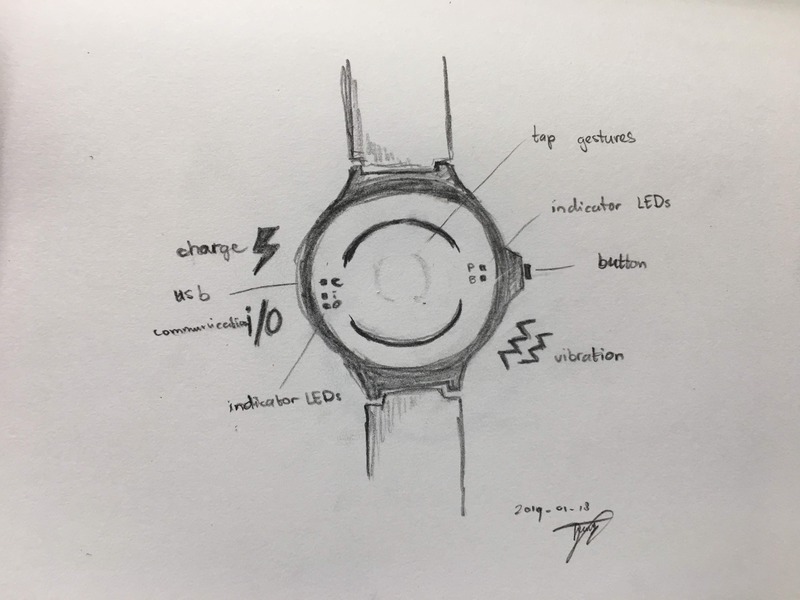
Topview of accessible smartwatch concept
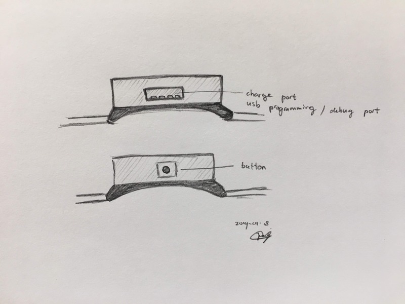
Sideview of accessible smartwatch concept
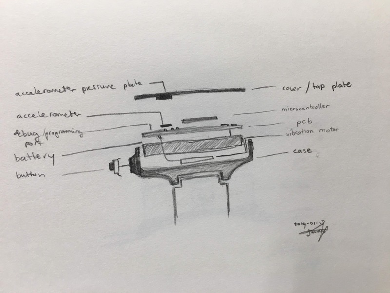
Decomposed view with components of accessible smartwatch concept
With my current sketches I defined the following components:
- round body (hollow cilinder)
- attached to the body on two sides (solid cube with cut out)
- attached to the mount a watch band (solid long cube)
- to the side of the body a button holder (hollow cube)
- on top of the body a round cover (solid cilinder)
Having decomposed your object in different basic shapes you can start defining your order.
The list I composed is order in my order of creation.
Next you can define your measures. What diameter should your circle be? And what height your box? I defined my measures for most basic components.
When you have sketched your idea, defined how you are going to create it and what sizes you are going to use, you are ready to create your actual shapes in your modeling tool.
Creating 2D project file (sketch) in Fusion360
With Fusion (as most modeling tools) you can create first a 2D shape to later create a 3D shape out of.
If you have created an impression and defined your components and dimensions, you can store your dimension in Fusion before you create your shapes. Using variables in Fusion360 allows you to later create components that would follow these exact measurements. Also this way you can later adapt the size variables in your design if something should be bigger or smaller.
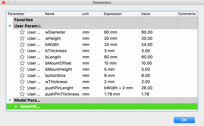 The first itteration of my variables for my smartwatch
After defining your variables, you can create your 2D shapes using your components list.
Keep in mind to create a 2D sketch in such a way that it will be easy to create a 3D object from it in Fusion360, so work in a top down view.
Then create your components as squares and circles and adjust their size to the defined variables.
Use the option ‘sketch dimension’
select the border of the component you want to assign a variable to
and instead of typing in a number, type the variable name.
Since you allready created your variable, Fusion360 will recognise it and auto-suggest the variable.
You can see if your variable works by adjusting the variable size in the properties menu.
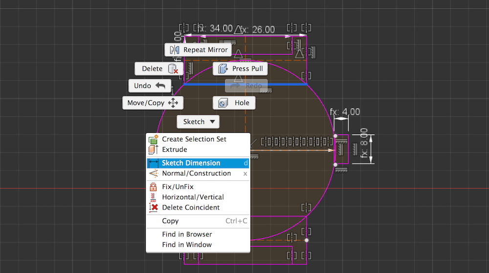
Sketch Dimension menu
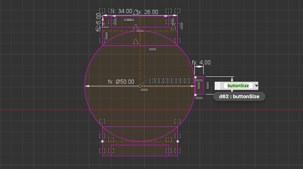
Sketch Dimension variable
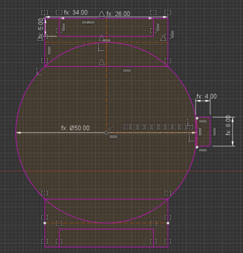 2D sketch of smart watch body
My top down view of an empty body shape, that should be simple to produce, normal looking, but sturdy in design. A band is tipically connected to two sides of the watch body.
To create two identical components (in my case band connectors), you first created one connector and use the mirror function to mirror the component to the desired location.
Be sure to select the full component that you want to mirror.
Then you select a mirror line. In my example you see a dotted mirror line I created in my circle to allow me to mirror my connector square.
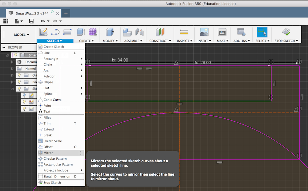
Mirror function in menu
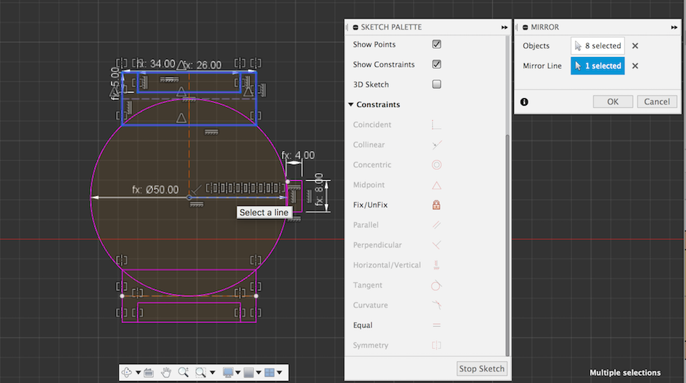
Mirror function applied
Combining shapes with constraints
You can create complex shapes by combining simple shapes.
You can ‘glue’ them together using a feature called constraints.
For example I glued a box with two corners to a cirle using the coincident constraint.
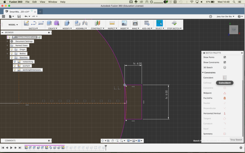
Be aware! Constraints can lead to a difficult to change shape.
You will notice this when you try to add more constriants to a shape, or the change a shape it size.
You will receive errors about to many constraints.
Most of these issues can be resolved by checking the contraints of all shapes involved.
Every time it will probably be different constraint, but at least you now know what to look for.
Examples:
I had once the dimension of the circle was set and therefor did not allowed the circle to scale to the new constraints. After removing the circle dimension everything worked.
An other time I had to many midpoints.
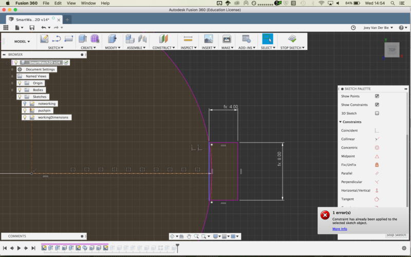
A constraint error
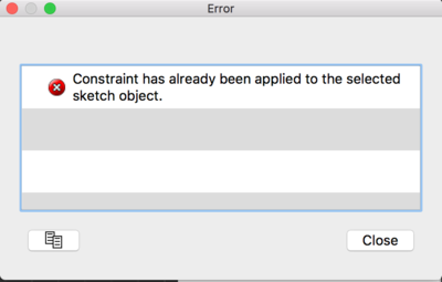
An expanded constraint error
Dimension issues with Fusion360
I noticed I made my 2D sketch far from the center of the axis. When I moved my sketch to the center and after restartion Fusion360 I lost my indicators of the dimensions. The strange thing is my dimensions are not applied anymore, so if I change them in my parameters it does not change in my sketch. I am also not able to apply dimensions again to my existing sketch objects. New objects did accept dimensions, so I knew it has something to do with the sketch object. I tried several things, like removing all constraints resizing, uncoupling the objects, nothing helped. In the end I recreated the entire sketch for the second time, this time because I know what I had to do I created my 2D sketch within 10 minutes instead of 3 hours!
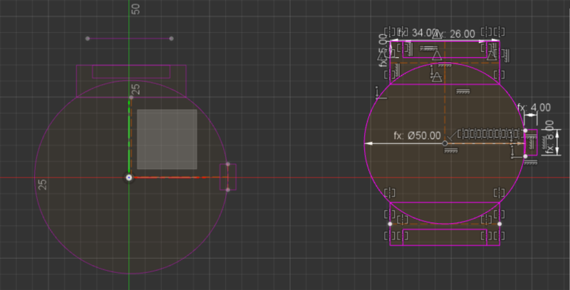 The two 2D bodies, one without working dimensions and a new one with
Creating 3D object in Fusion360
I created a 3D object by extruding, cutting and making holes from my 2D sketch.
I could easily extrude the watch body from my 2D sketch using the extrude function. The height was specified with the watch height parameter.
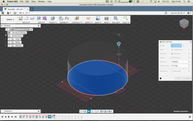
Extrude watch body
Now the body is a solid cilinder, to make it an empty cilinder with only a wall I used the shell function. The wall thickness was specified with a parameter.
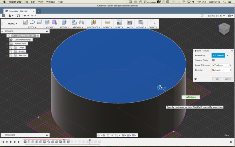
Shell watch body
Then extruding the mounts and joining them to the body using the join option in the extrude pane.
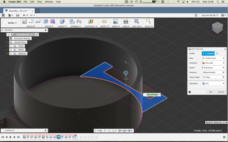 Extrude watch mounts
For cutting the holes in the mount, I first cut one hole, and than duplicating the feature with a rectangle pattern to cut the remaining 3 holes.
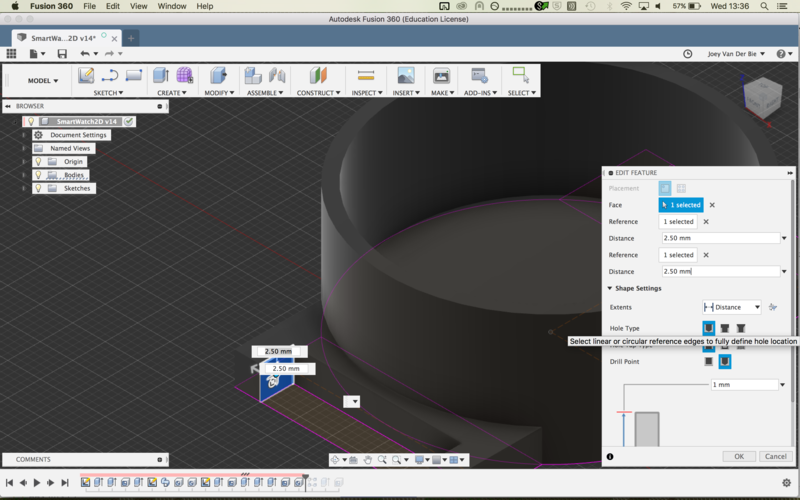
Cut 1 hole
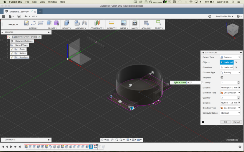
Cut 3 remaining holes using the feature as a pattern
Then I created the button mount. By applying an offset half the watchbody height and using symetric extruding I got the right shape in the middle of the body. Then making a shell out of it. The wholes for the button I could not create at this moment, since I do not know which type of butten I am currently using.
Last I created the cover for the watch body, again by extruding the watch body circle, but with an offset of 2 times the watch body height and a thickness of 2 mm. Than at the bottom of the cover and outside shell of 2mm to make a tight fitting cover.
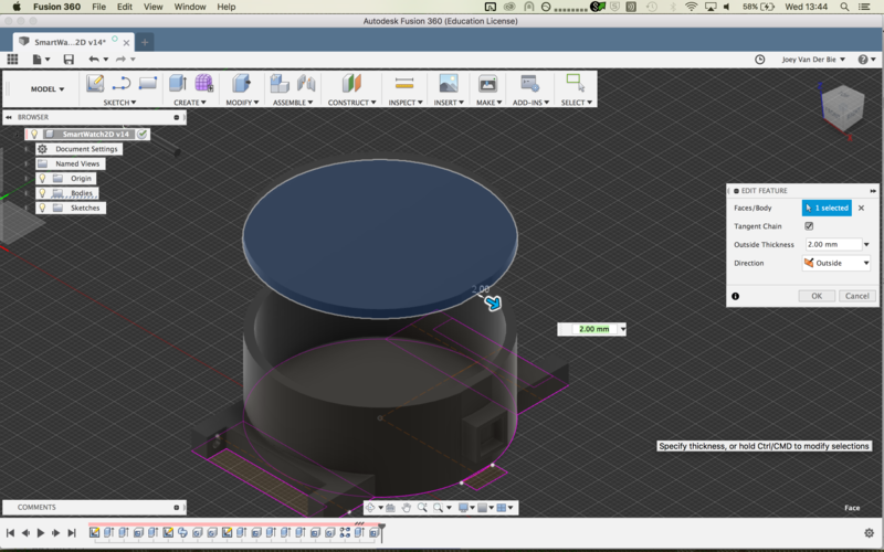
The cover of the watch body
Fusion360 made it all really easy and I encountered no problems, how hard I tried. The workshop of Mauro really had a great effect on my speed and efficiency of working. Because of by dimensions issue I created the body almost fully twice, but the second time took me only 2 hours!
Notes:
- For my 3D object I am currently asuming it will be 3D printed. If I create a wood model out of it, I will (have to) redesign the shape and variables. I had to make one important decision, the thickness of the wall of my main watch body. I guessed a sturdy but not overdone thickness of 2mm is sufficient for a 3D print. But is it? I hope to have the answer in a few weeks when we arrive at the 3D printin.
- If you compare my 3D object with my paper sketch, you notice I did not made it smooth. After observing existing smartwatches, I noticed this smooth design is not needed, and might even be less functional than a clear straight desing. So better to first try a straight desing and refine it when needed.
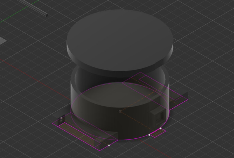 The 3D object created from 2D sketch
Creating patterns
Creating pattern out of 3D shape.
First time worked as a charm,
second time I tried a more complex shape, one created out of combined 3D objects.
I was not able to use this shape as a pattern.
Mauro explained this can happen when the shapes are overlapping and or not properly joined.
Unfortunately I did not found out what was my specific problem, so my only option was to try again with a new shape.
And with the new shape everything worked, and I was able to create a nice pot.
Sculpting mode - Digital Clay
In Fusion360 you can mold your own shapes as digital clay with the sculpting mode. This is a great option, only also difficult. It it very easy to overlap points resulting in impossible shapes, which you cannot 3D print for example. The trick is to switch between different views with the options, command + 1, command + 2 and command + 3. The first command shows you the boundaries of all the vector points, the third command a rendered view and the second command a combined view. In the boundaries view you can quickly see how points overlap, while in the third view you see your actual result. Mauro made is easy for us to tell us to start with as few points as possible and only add complexity (more points) at the specific place where it is needed. I was allready familier with this type of working with 3DsMax and it felt very natural and I did not encounter any more problems.
OpenSCAD and OpenJSCAD
I week 15 for the machine building assignment I designed the 20 marble gates in a new 3D designin tool I had not tried for a real project: OpenSCAD.
I switched to a simple and small CAD design tool OpenSCAD. It is a function representation design tool, meaning you write code to model your design.
It reminds me of the 3D objects I made in Processing during my Masters, and I am curious how fast it will allow me to design a complex shape.
OpenSCAD can be downloaded from http://www.openscad.org.
Or install on a Mac via MacPorts:
$ sudo port install openscad
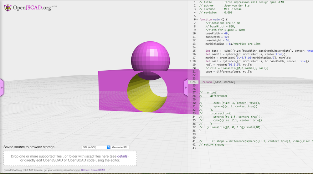
While waiting for OpenSCAD to install you can try out its brother: OpenJSCAD, a online browser version of the modeling tool.
It is almost the same in functionality, not in code. Documentation can be found at https://openjscad.org/dokuwiki/doku.php.
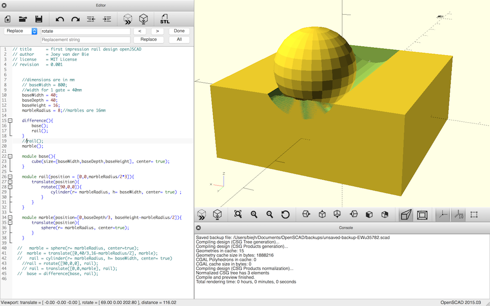
To create a shape in OpenSCAD: start the application and start defining the shape function with its parameters.
The list of functions available can be found at http://www.openscad.org/cheatsheet/index.html.
I tried to translate the OpenJScad code to OpenSCAD code, but as can be seen in the code the basic idea and parameters are the same, but the whole code structure is different.
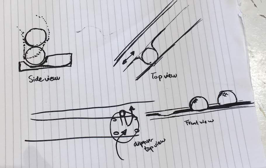
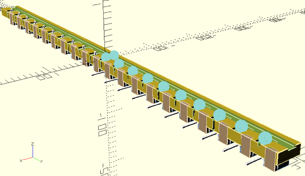
For the rail design I created a test with 2 time gates. I made the design modulair and parametric. This allowed me to first design one time gate module, which I call a cell.
To create multiple cells I can call the cell() function and move (translate) the cell to the correct position.
Also for the rails I created a rail() module, that I used for both the rail as for the gates.
The dimensions I used were:
- rail width 16 mm
- rail depth 8 mm
- gate depth 8.1 mm
- base width 40 mm
- cell size 40 mm
After designing the first cells I had to conclude that the design in its current form was unmillable given the time. I used cilinders and substracted them from the base (cube) using the function difference() to create nice rails. Unfortunately milling these shapes will take up a lot of time.
Adobe Illustrator - intermezzo
To quickly resolved my issues with the 3D not-millable design by thinking in cubes.
I modified my design to use cubes in stead of cilinders and made a 2D topview design in Illustrator that we could use to mill.
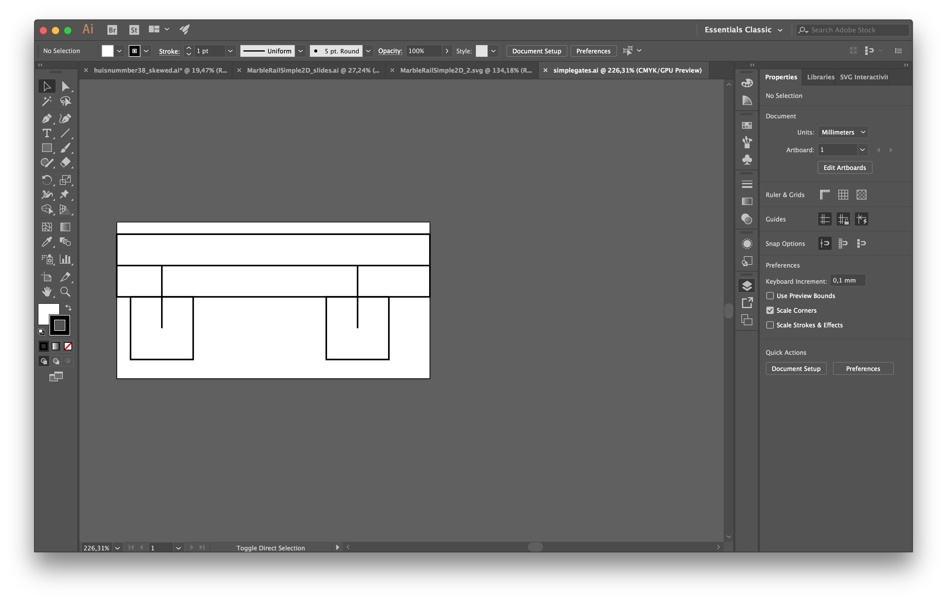
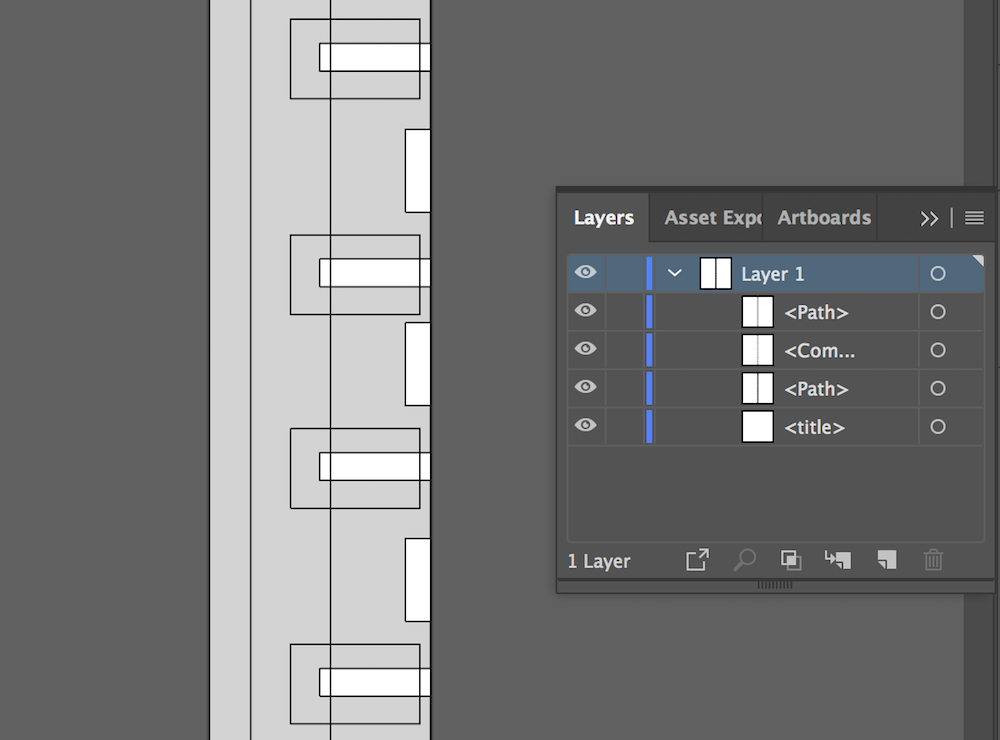
Illustrator is a vector drawing tool. The great things about vector tools is that your desing is rendered instead of stored in pixels, this makes removes scaling issues as blurring or artifacts that do accur in pixel based drawing tools as Adobe Photshop and Microsoft Paint.
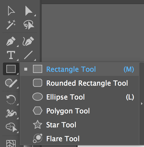
For this desing I used the “Rectangle tool”, it allows you to quickly create 2D boxes, squares or rectangles.
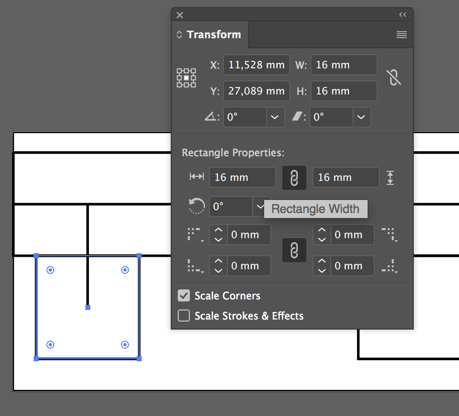
You can click and drag with the mouse to create the correct rectangle shape, but I like to click and change the dimensions in the dimensions section.
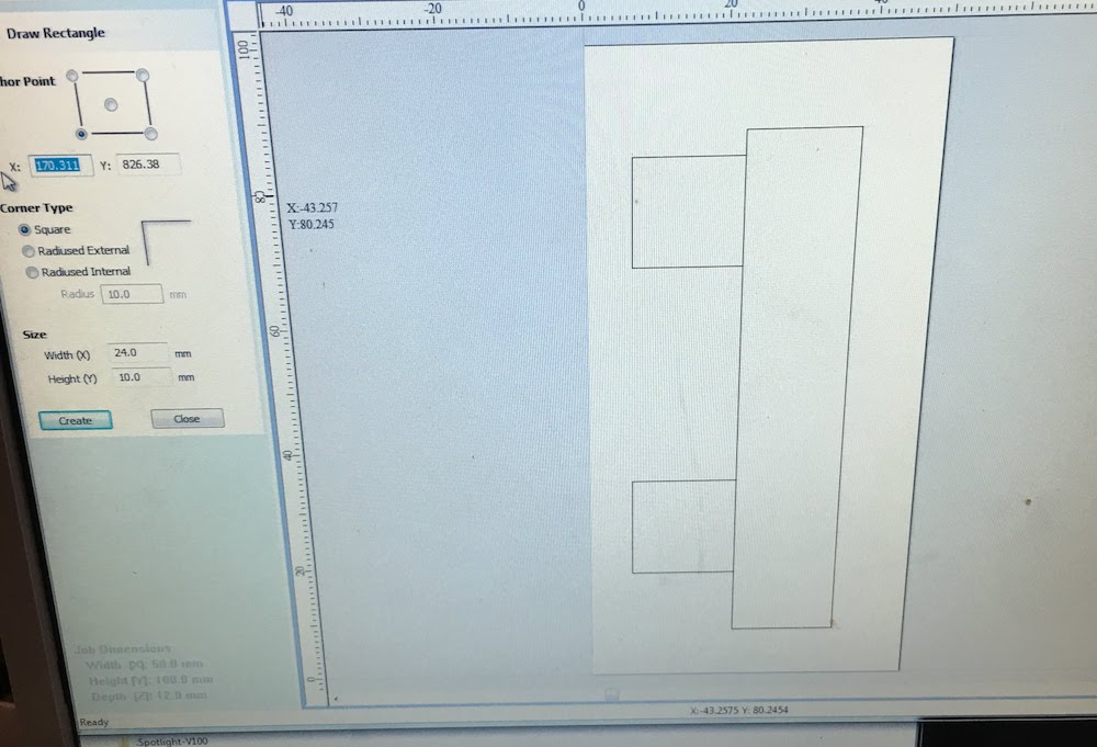
For example, for this test I made the marble gates 16 by 16 mm, exactly one marble wide.
 I alligned the rectangles by moving them via the Transform window.
This allows me to place them pixel perfect.
I tried to align shapes in Illustrator in the past using the alignment option, but noticed in the Computer Controlled Machining week thatthe aligned of the shapes is not pixel perfect.
Adding a servo to the rail
After milling a succesfull first test, we decided it would be nicer if the marbles would be more visible, and the gates should be a little more deeper than the rails. I made the rail a little less wide and deep to allow the marbles to be more visible.
Also when placing the servo near the gate, I concluded the gate needs a cutout for the servo arm.
With a saw and chisel I created a cutout to test with the servo.
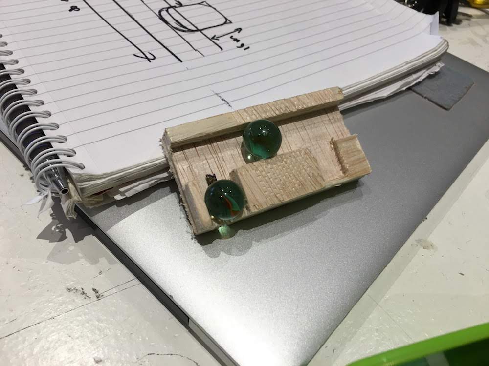
I further enhanced my digital design to allow for a servo mount to be added to the base later.
First priority this week is the gate, the servo is in a week from now.
To create the optimal mount I had to create a servo module, representing the servo in the digital space.
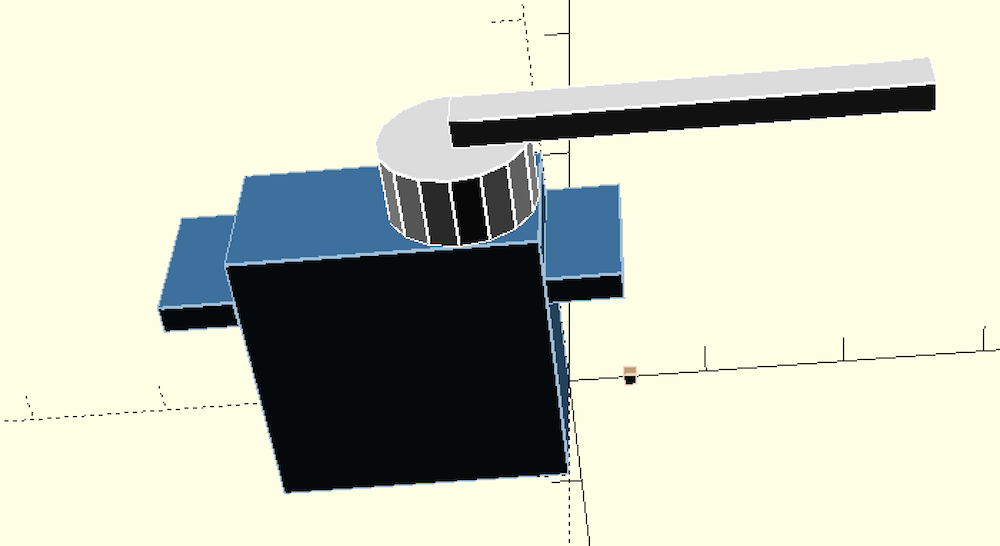
With the color() function I added colors to make the different components more distinct. Combining everything together our digital rail design with servo’s looks pretty impressive.
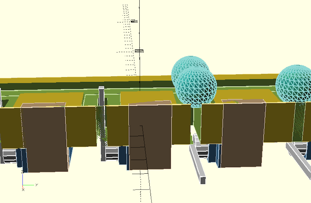
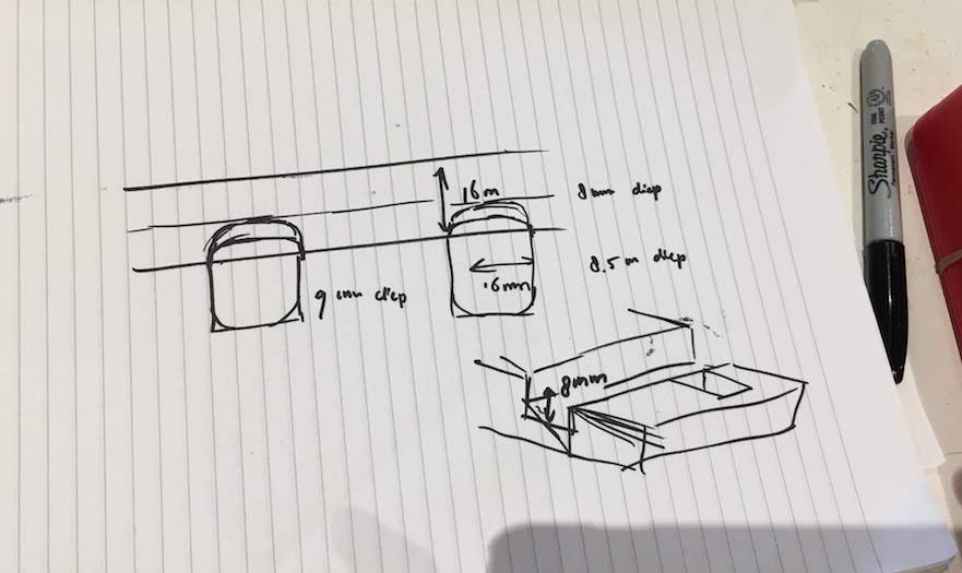
I adjusted the first desing to the final design with the following parameters:
- rail width 14 mm
- rail depth 6 mm
- gate depth 6.2 mm
- base width 800 mm
- cell size 39 mm
- servo cutout width 5 mm
- servo cutout depth 16 mm + 7 mm (1 marble + 1/2 a rail width)
From 3D to 2D in openSCAD
Having decided on the final design I tried to transfer the 3D design to a 2D design and vectors to be able to mill it.
This was more difficult in openSCAD than anticipated.
I had to replace all 3D functions for 2D functions. e.g. replace cube for sqaure.
Also I had to modify the 3D translate() and the rotate() functions to fit the 2D actions.
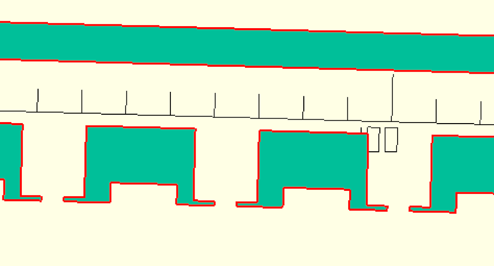
Last in exporting the design to SVG I had to conclude the software would join all the shapes, creating one big blob.
I tried to unjoin this in Illustrator, but was unsuccessfull.
My sollution was to export each object as an idividual SVG and combine these files in Illustrator to one file.
Also the size is different when exporting, the width was 14 mm instead of 40mm , by adjusting the size in Illustrator you get a correct size SVG.
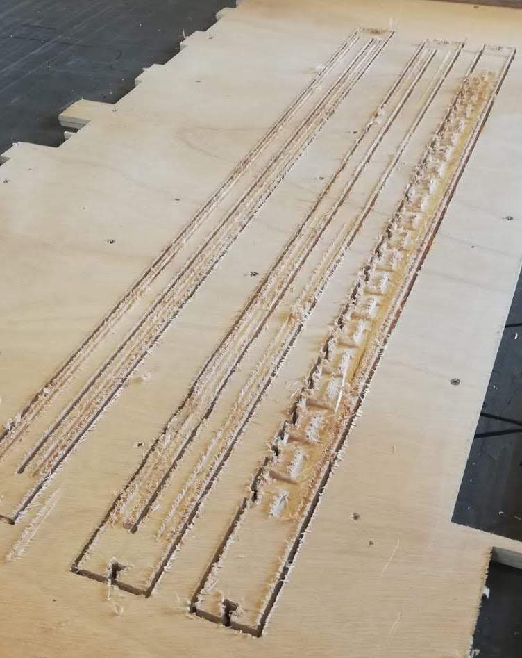
I shared the SVG with the team, and Anne added the connectors of Micky’s frame and Rutger milled the rails, this is teamwork!
Projection?
I later learned openSCAD has a projection function, which should allow you to project a 3D shape to 2D.
You can use the projection() function by placing it in front of the shap you draw.
It does inpact other functions, for example join or difference.
So I was only able to place the projection function at the start of my drawing, before the difference function.
Resulting in exactly the same unmillable 2D blob I had when trying to export to vector.
Final project research choices
The great thing about trying to create your final project in different tools is that you are confronted with different design decisions. This week it was all about exact measurements, and I had to consider al the exact shapes and sizes, e.g. diameter of watch, watchband type and size.
Chosing a band type and size
Watch bands come in different shapes and sizes. I searched different watch band shops as https://www.dehorlogebandenspecialist.nl and https://www.horlogebanden.com/ for what available types and sizes are. I found there is a wide range of widths, starting at 8mm till 30mm. Most available bands are around 20mm and 24mm. So for now I will use a bind width of 24mm. A common, but big size, this allows me to easily try out different bands, and to keep my watch big. Further for quick prototyping I have velcro band and rubber bands that I can quickly fix to the watch body.
Connecting the band to the watch body
Then I could chose a band connector to the watch body. I know there are magnet connectors, slide in mechanism and pushpin axels.A simple Google search for watch band connectors shows allready many different types. I figured I should not try to invent the wheel on every part of the watch, so I went with the most common, the push pin. The push pin also comes in different sizes for different band widths. Since I use a band width of 24mm, my push pin should be at least 24mm. To be at the save side I want to use a pushpin of 26mm and let is rest a little deeper in my watch, since 3D prints arent always that stirdy. But time will tell if I really need to take this drastic measure.
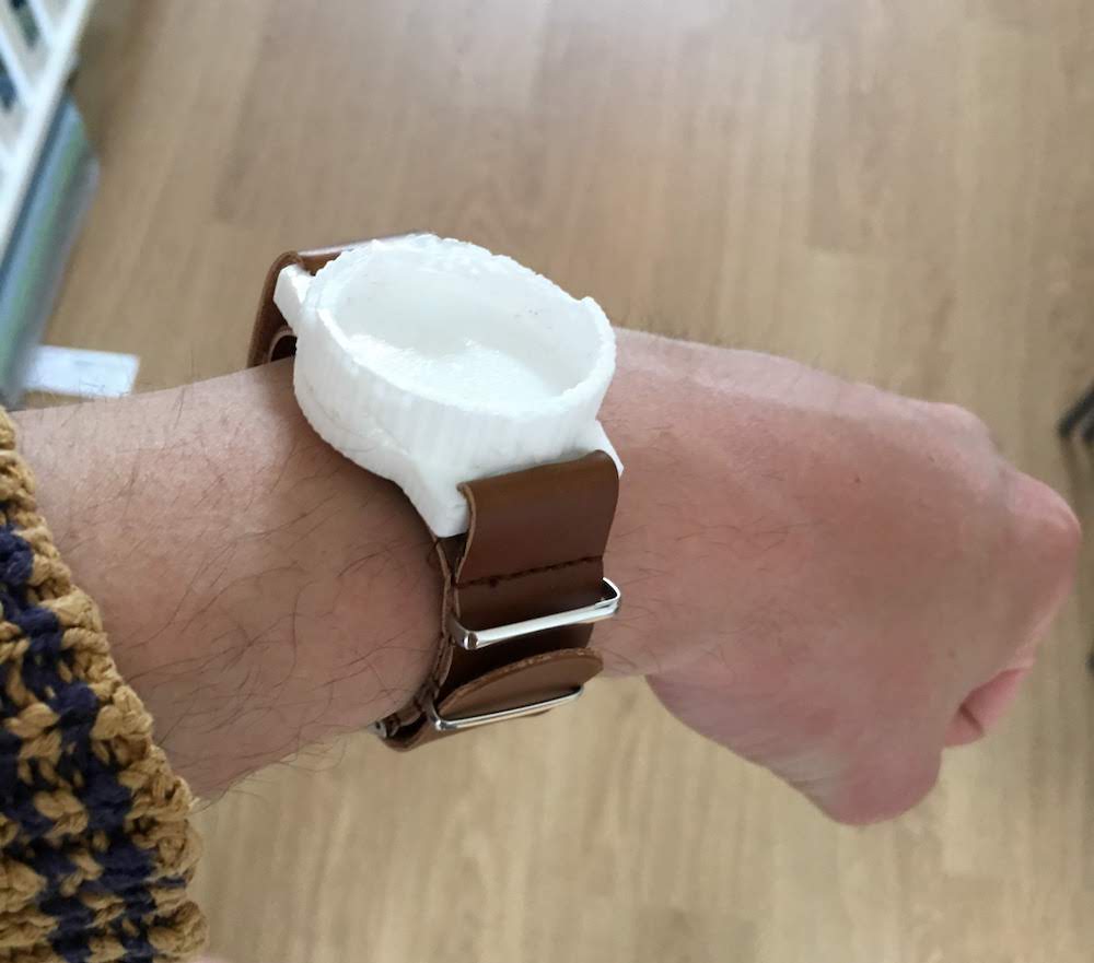
Connecting the band to the watch body part 2
During the molding and casting week I decided the pushpin connector will probably be to fragile to use on a daily base.
Therefor I edited my 3D design to have slots where the watch band can go through.
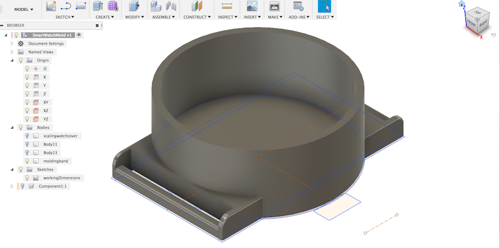
For the watchbands I ordered a leather and nylon band from China (Ali Express).
A few weeks after casting the mold the bands arrived, and I was able to test the result.
The slots fit perfectly with the ordered bands!
I need to do-over my mold to have a nice plastic mount, but with this first prototype I proved to myself this type of casing can work.
Failures
Combining shapes with constraints
You can create complex shapes by combining simple shapes.
You can ‘glue’ them together using a feature called constraints.
For example I glued a box with two corners to a cirle using the coincident constraint.
Be aware! Constraints can lead to a difficult to change shape.
You will notice this when you try to add more constriants to a shape, or the change a shape it size.
You will receive errors about to many constraints.
Most of these issues can be resolved by checking the contraints of all shapes involved.
Every time it will probably be different constraint, but at least you now know what to look for.
Examples:
I had once the dimension of the circle was set and therefor did not allowed the circle to scale to the new constraints. After removing the circle dimension everything worked.
An other time I had to many midpoints.
Dimension issues with Fusion360
I noticed I made my 2D sketch far from the center of the axis. When I moved my sketch to the center and after restartion Fusion360 I lost my indicators of the dimensions. The strange thing is my dimensions are not applied anymore, so if I change them in my parameters it does not change in my sketch. I am also not able to apply dimensions again to my existing sketch objects. New objects did accept dimensions, so I knew it has something to do with the sketch object. I tried several things, like removing all constraints resizing, uncoupling the objects, nothing helped. In the end I recreated the entire sketch for the second time, this time because I know what I had to do I created my 2D sketch within 10 minutes instead of 3 hours!
Fusion360 not working offline
Over the past weeks of using Fusion360, I have received more and more errors when trying to work offline.
Since May I have difficulties even booting the software, 9 out of 10 times it crashes before being fully loaded, and won’t even start when I am offline.
Also I have version issues when working offline, sometimes it appears that when I load my creating after working offline, I have lost my last edits!
These unrealiabilities have me moving away from Fusion and trying out other tools as openSCAD.
Not able to download FreeCAD
For the marble gates design I decided to create the first impression in FreeCAD.
It is my first time with FreeCAD, but having tried Fusion360 for several designs, it is time to try something new.
On the FreeCAD website we read FreeCAD has many features that I am now used to thanks to Fusion360: complex 3D shapes, parametric design, support for standard formats as obj, simulation and rendering.
Unfortunately at the time I needed FreeCAD, I was unable to download the software, even after multiple tries. The download is almost 600mb, but I never got further than 80mb. And after 1 hour of trying I decided to try a different design tool.
I was not able to determine if the failure to download the file was in due to my connection or the FreeCAD website.
Reflection
Reflecting on this week I am really impressed by how fast I could learn a new tool like Fusion360 or OpenSCAD.
The workshop by Mauro was great! Mauro had a high pace, but enough pauzes to give you confidence during the designing.
Also it was very complete, covering more than just te basics.
Having said that, during the weeks in Fabacademy I noticed to much issues with Fusio360 due to connection issues, making me less fond of the tool over time.
After having tried out OpenSCAD, I think that for most designs this simple 2D and 3D programming tool allows me to make and edit designs way faster, without having connections issues.
Fortunately I can continue using both, from OpenSCAD I can export my design and import in Fusion, allowing me to do complex tasks that are not easy to perform in OpenSCAD with Fusion360.
For my project is is great to finally see my design in 3D, giving me an impression if my idea is feasable and allowing me to think about complexity of fabrication.