
Week 5. Electronics Production
5. Electronics production
Software
Mods http://mods.cba.mit.edu Mods allows you to convert PNG images to instruction code (in RML-1) for the Roland MDX-20 mill. It is developed by MIT, available as an online tool, and can be extended using several mods.
Hardware
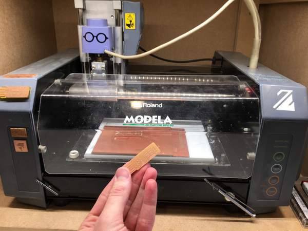
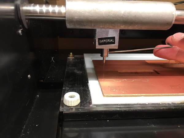
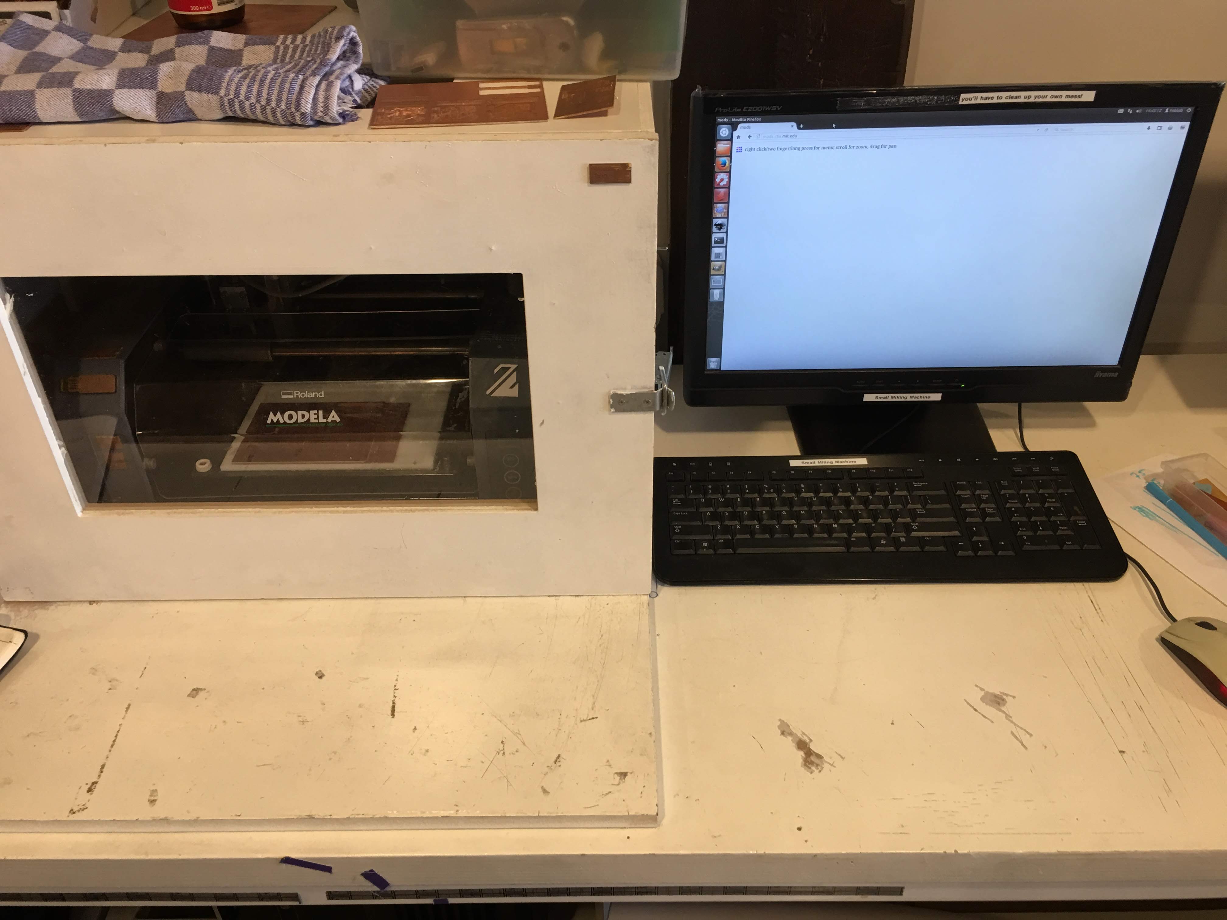
Roland Modella MDX-20 mill
The MDX-20 is a computer controlled milling machine that allow you to cut away small materials in 3 dimensions (x, y, z), but only from top to bottom, we call this 2,5D. It can work really precise and we will use it for milling coper plates to create our own PCB design.
The MDX-20 can be controlled via the computer using the Roland Machining Language (RML-1). These instructions can be created using Roland’s own software and FreeCAD, but we will be using Mods.
Source https://www.craftweeks.com/post/162856783101/mdx-15-20-faq
Roland MDX-20 user manual
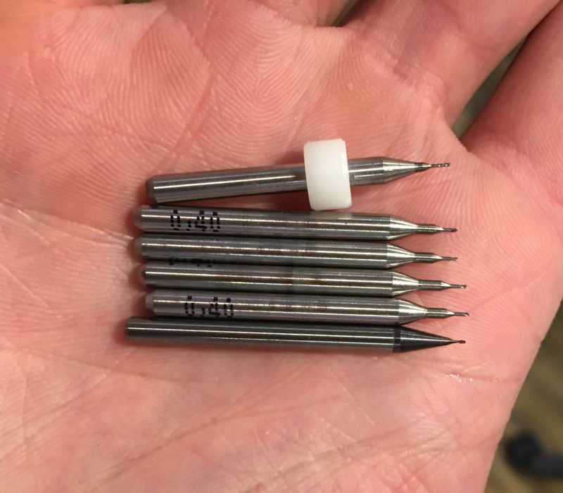
the mill bit for traces - mini end mills two flutes 0.40 mm 826
the mill bit for cutout - two flutes 0.8 mm
Multimeter
Knife
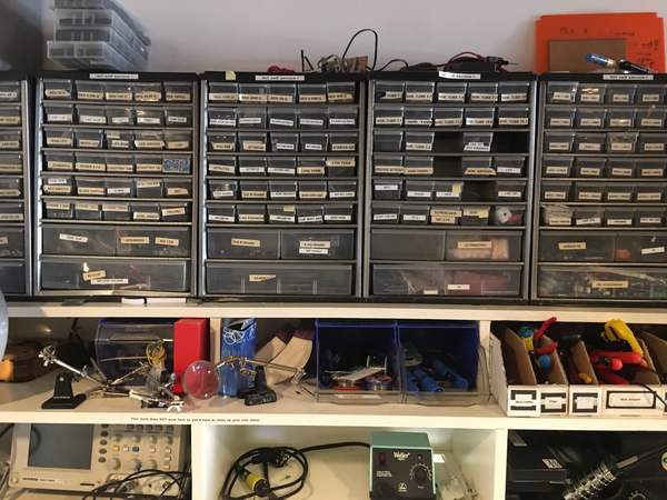
Anti static tweezers for electrical components
Solder iron
Solder tin
And various surface mounted components
Files
Traces file for FabTinyISP
Cutout file for FabTinyISP
Line test file for group assignment
Cut out file for group assignment
Before you start
- No long hair, sleeves etc. When soldering you can turn this on fire and when milling it can get stuck in the mill.
- Do not be static, you are working with sensitive electronics, static electricity can break it. Remove your static by touching a grounded metal, like a radiator or wear anti-static arm band.
- Provide good ventilation and work clean. You are working with potentially toxic material.
- Wash your hands after you finished your work.
What is a PCB
PCB stands for Printed Circuit Board. It is not always printed, it can also be edged or milled, but does provide the board with the circuit lines. This workshop will be focused on creating a circuit board using a milling machine.
Creating a circuit board using a milling machine
We are going to create a circuit board using the Roland Modella MDX-20 mill.
And a two flutes 0.4 mm mill bit for creating traces and a 0.8 mm mill bit for cutting the board.
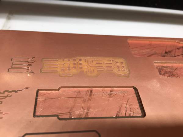
For the board it self we use copper plate FR-1. The base of this plate is made of 1.6 mm paper with a top copper layer of 35 micro meters. (link to specification of the FR-1 copper plate)[https://uk.rs-online.com/web/p/plain-copper-ink-resist-boards/4539057/]
The board we are going to mill is the FabTinyISP, a programming board that will allow us to program an Atmel micro controller via your computer.
Files can be found at the site of FabAcademy
Tracelines
-
Create or download your design.
You will need a PNG file that provides the circuit lines the mill needs to trace and a cutout file the mill needs to cut.
We are using the files from FabAcademy:


- Copy the files to an USB-stick.
- Start the computer that is controlling the milling machine and copy your files on the computer.
- Turn on the light of the milling case (top right switch at the outside of the case)
- Open de case around the mill and the cover of the mill, remove the screws that are attached to the base plate and take out the base plate.
-
If there are existing copper plates on the base, remove it using a scraper (spatula) Keep the “Do not use this layer” plate on the base plate.
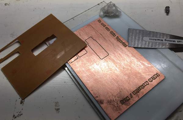
Make sure you leave a nice flat surface for you new copper plate.
If necessary use sticker remover solvent to clean the surfaces.
- Place your copper plate on the base copper plate using double sided tape. Spread the tape evenly and do not let the tape overlap.
Do not clamp the board to the milling machine, clamping could bend the board, resulting in errors in your milling, thus circuit.
Cover it with a cloth or towel and put a lot of pressure on it to make sure it is firmly attached to the base and leveled.
-
Place your plate back in the mill and attach the screws. Tighten them by hand, but not to tight.
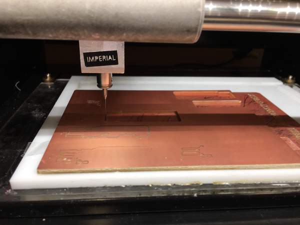
- Take a mill bit (in our case the 0.4mm) and place it in the mill head. Be careful! The bit is very delicate and sharp. Dropping the bit will break it and do not touch the pointy end.
Put the bit between two fingers and place it in the mill head. Tighten the screw on the right side of the head enough to hold the drill. -
Put your finger softly on the bit, unscrew the screw a little bit. And softly push the bit as high as possible and tighten the screw again.
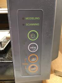
- After installing the bit, turn the machine on (on button). The drill head will move to the right and pause. The view button allows you to pause or resume the machine. This way during milling you can get an overview if everything is going as planned.
-
Press view button to get the machine out of pause state and in ready state for loading programming code.
- Go to the computer and load the mods application using URL http://mods.cba.mit.edu/
-
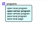
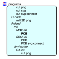
Press programs -> open server program and scroll to.
Roland
mill
MDX-20
PCB
- The program will load the software for the Roland MDX-20 mill. It will talk RML-1 code (X, Y, Z positions) to the mill.
The small modules on the bottom are modules that create the RML-1 code.
The modules on the top are the ones we are going to have interaction with, they allow you to configure the machine. Then you flow from the left to the right to load, convert and send your program to the mill.
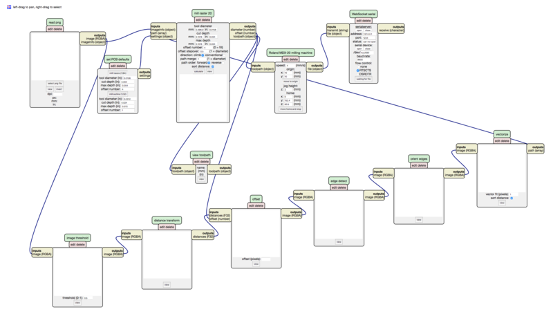
- We start with the most left module, it allows you to load a PNG image of a PCB design. It only supports PNG, because of the properties of the format (pixel perfect and retaining dimensions).
Load your traces PNG file. - Go to the “set PCB defaults” mod and press the “mill traces” button. This mod will be filled with the values for cut depth.
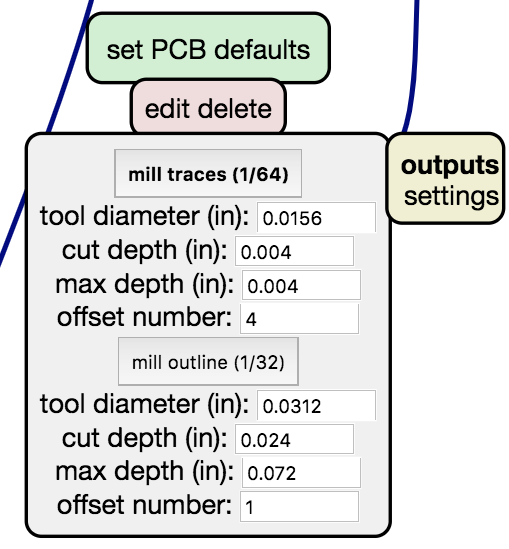
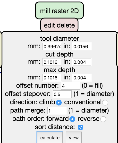
- Got the “mill raster 2D” mod and set the tool diameter to 0.4 mm.
If you see the inches translated different than the tool diameter in inch on the “set PCB defaults” mod, than copy this new value to the defaults mod.
Set the cut dept and max dept to 0.004 inch.
Set the offset number, this is an offset around a traceline. This offset tells the mill how much copper it needs to remove around the trace.
The number is the times of lines it will remove next to a trace. Setting it to 4 tells it to remove 4 drill head lines next to a trace.
The default number is 4. We will keep this as is.
Setting it to 0 will tell the mill to remove all coper that is not a trace line. - The offset stepover is a number between 0 and 1 and indicates the stepover width as a percentage of the drill diameter.
Set it to 0.5, so 50%, or half a mill width. Setting is to half will let the mill overlap its own trace by half, reducing the stress for the mill bit.
Recommended is to let the number of lines and offset in total add up to at least 1 mm, making it easier to solder. - Direction, always use climb, this will tell the drill to turn clockwise, reducing the stress on the bit and making sure it wont unscrew itself.
- Leave path merge, path order and sort distance as is.
-
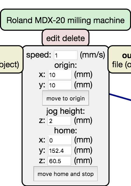
Go to the “Roland MDX-20 milling machine” mod.
Set the speed setting to 1 mm/s. The bits are very fragile, so slower speed means less stress on the bit.
This is speed of travel of the mill bit on the X and Y axis, not speed of rotation (speed of rotation is always the same on this mill).
The origin is the starting location of the mill.
The jog height (Z) to 2mm, this is the height the bit will lift when jumping from one trace to another trace.
- Go to the desktop and open the serialserver.sh file, select “open in terminal”. This will extend the USB port to a local web address for the software and tells you its server address (localhost/127.0.0.1) and port (in our case 1234).
- Go back to mods and to the “Websocket serial” mod. Make the address and port the same as the values given in the terminal
Keep usb to ttyUSB0,
baudrate to 9600,
and use RTSCTS. - Connect to the serial device by pressing the serial device: “open” button.
-
Then connect to the serial server, by pressing the “open” button at serialserver.
- Now it is time to calibrate the milling machine to the height an position of your board.
- Go back to the Roland MDX-20 milling machine mod and look at the origin values.
- For setting the origin we need to set the mill’s correct starting position, X,Y and Z. Setting the X and Y values first. This is the easiest when the mill bit is close to the plate. Press the down button on the device and keep pressing it till it is either a few millimeters above the plate or as low as possible. This adapts the Z axis of the mill. Press the up button to move it a little bit up, a few millimeters. The height should be at least a distance you want to mill later.
- Play with the origin X and Y values to move the mill bit to the left bottom position of your plate where you want to start drilling.
- Move the mill bit on the plate by:
Put your finger on the side of the bit and slowly untighten the screw, and let the bit slowly lower on top of the plate.
DO NOT tighten the screw yet. - Turn the mill bit base a little bit with your finger to remove the dust between the drill and the plate.
- Tighten the screw of the drill.
- Now the machine is ready to start milling. You need to send the instruction code (RML-1 code) to the mill. Go back to the “Mill raster 2D” mod and press the calculate G-Code button. You will see the bottom modules generating the code form he PNG.
- When it is finished it show an image with the lines it will drill.
The blue lines are the milling lines, the red lines the traveling lines (jog distances). The arrows indicate the direction.
You can check your outcome for faults. If you do not see blue lines, there will be no drilling.
Note that after every change you make in the mods you need to calculate the G-code again. - When everything checks out, you can place the cover back at the mill and close the mod.
- Take a picture of your settings, your origin and milling settings. This is because, sometimes the mill will have an error and will stop before it is ready milling, or you might have set milling depth not deep enough.
By knowing your values and origin you can restart the milling procedure and reuse you existing material. -
Go to the “WebSocket Serial” mod and press the “Send file” button.
This will start the mill.
- When the mill is done, it will move the plate to the start.
- Clean your plate using the vacuum cleaner.
Cutout
Cutout settings:
- speed: 4
- mill diameter: 0.8
- cut dept: 0.6
- max dept 1.8
- leave the other values to default.
We traced the lines, now it is time to cut out the board.
- Change the bit carefully with the 0.8 mm cut mill bit.
- Open the cutout PNG
- Press mill outline in the “Set PCB defaults” mod set the mill diameter to 0.8 and transfer inch values if needed
- Set the speed to 4
- Check max cut dept, it should not be to much beyond your PCB dept.
- Set the mill bit to your origin.
- Set Z axis on the mill by moving it up and lowering the bit on the plate. Make sure it is high enough to be able to reach the max cut depth.
- Press calculate button and you will see the new images
- When you rotate the image you see the amount of lines it needs to drill to fully drill through the board.
- When everything checks out, you can place the cover back at the mill and close the image.
- Take a picture of your settings, your origin and milling settings. This is because, sometimes the mill will have an error and will stop before it is ready milling, or you might have set milling depth not deep enough. By knowing your values and origin you can restart the milling procedure and reuse you existing material.
- Go to the “WebSocket Serial” mod and press the “Send file” button. This will start the mill.
- When the mill is done, it will move the plate to the start. Clean your plate using the vacuum cleaner.
- If you are finished with this board, but need to cut more boards only remove your cut out board from the base plate.
- If you are finished with all cuts: Turn off the mill.
- Unscrew the base plate and remove it from the mill
- Remove your copper plate using a scraper (spatula) Keep the “Do not use this layer” plate on the base plate.
- Further clean the mill with the vacuum cleaner, put back all the covers and turn off the computer.
Note: this is the only machine that is allowed to keep running unsupervised at the Waag.
Protip: when the machine is running you can press view to pause it in between.
When you press view again it will resume its state.
Reset the mill
To stop your cut and reset the memory in the mill:
- Press the view button on the mill to pause the mill.
- Press the cancel button on mods
- Press the up and down button together on the mill for at least 2 seconds
- Press the view button again, this mill should no go to his default position and stop.
Design rules for PCB production process
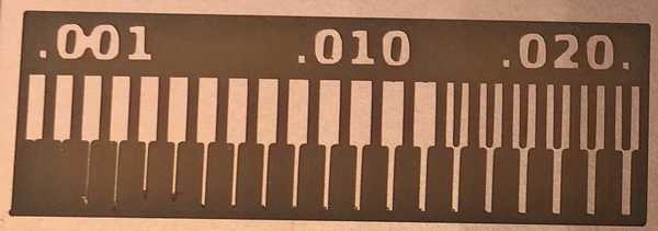
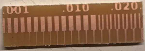
Circuit lines can only be fabricated until a certain thickness and distance of each other. Depending on your material and fabrication process the distance varies. With a PCB mill the range depends both on the mill and on the drill bit used.
To determine how small it can mill you can create a test board with the different line thicknesses and line distances.
 The linetest.png is an example of such a test board.
File provided was the correct size in mm, but the resolution is to high for this computer to run on mods.
We tried to correct the size using the Gimp setting it to 1000 PPI, but than the Gimp also changed the image mm size.
We tried scale and print size, both had the same effect. Because we did not wanted to change the size, only the pixels per inch we tried in illustrator.
In Illustrator we could resize using file->export->export as. change PPI.
We changed the file in Illustrator and copied it to the computer.
- Loaded mod software
- Selected linetestAnne.png file
- Mill traces button
- edited tool diameter 0.4 mm
- cut dept 0.10 and offset number to 4
- offset stepover 0.5
- loading sh file
- connecting to USB serial and server
- preff offset button and home button, nothing worked.
- We had to press the view button. The mill went automatically in. After pressing the view button the mill started following the commands send from the computer.
We changed the mill bit with the correct bit.
Placed the mill head ad the desired position.
Lowered the head and drill.
When calculating the file to G-code we saw that the end file looks strange.
Also it did not load the image.
We pressed the view button next to calculate and saw a very strange result.
We reloaded our settings via the “mill traces” button, changed the tool diameter to 0.4 mm again and changed the offset to 0.
We calculated the G-code again and looked at the new file.
It looked nice, we even peeked during the milling how it looked and it seemed ok.
We compared our result with the result Henk previously created and they looked pretty the same.
There was only difference in offset. Henk used an offset of 1 or 2.
We checked again and result was that we sometimes were pressing the wrong view button, a good example of group inefficiency.
Also there was an error in the mod software, which was resolved by reloading the software.
For the cutout we reloaded the browser to remove all the errors and start over.
We loaded the cutout file.
Pressed the mill outline button.
Checked the tool diameter 0.8 and cut dept.
set speed to 4.
Moved the drill to origin.
Placed the cutout bit in.
Calculated the the G-code and send the commands to the mill.
The result was a cutout that was too much on the inside.
We made the cutout file by making the tracelines file black.
We can think of two reasons why we cut at the inside:
- Either the black rectangle was to small
- Or the mill mills on the inside.
After looking at the PNG options we saw that we could invert images.
After inverting the image and looking at the calculated result we concluded we had to invert the cutout image.

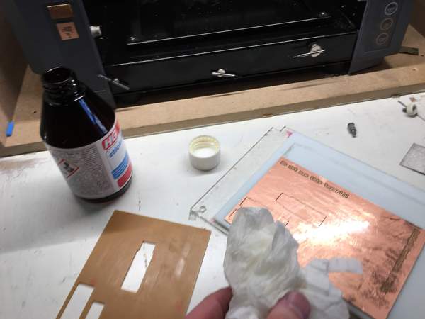
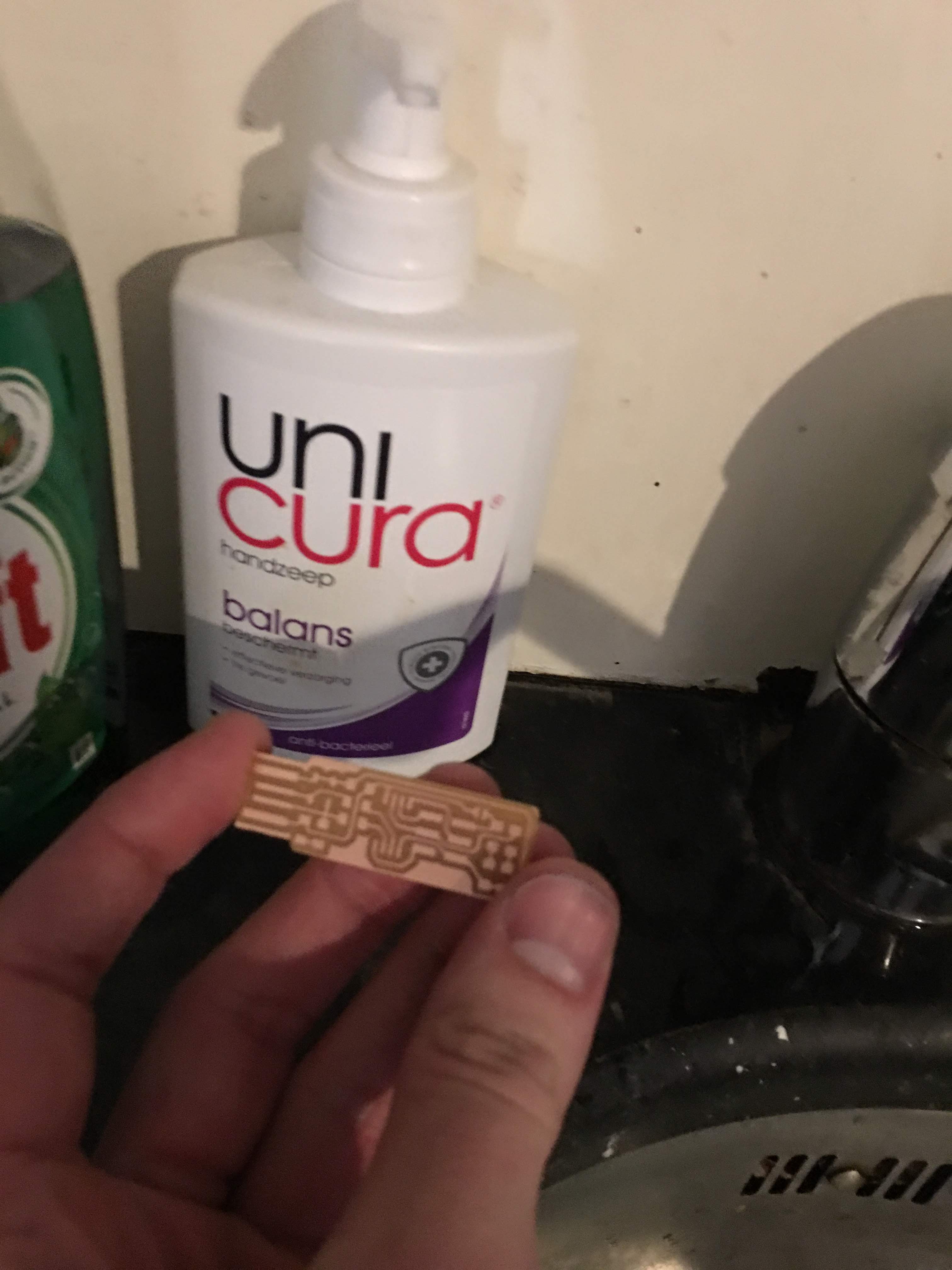
Cleaning the PCB
Clean your board using soap, any kind of soap will do, but try to use soap with a lot of added chemicals.
- Rub soap on the board
- Rinse with water, preferable distilled water.
- Dry the board.
- After cleaning do not touch the circuit again.
Hand soldering
There are different ways of soldering, we will discuss soldering by hand. But it is good to know there are also more production ready processes as reflow soldering, where you place your components, apply solder paste using a mold and solder all components by baking the components in a reflow oven. With hand soldering you can use clamps, but when applying surface mounted components it is easier to lay the board flat.
Before you start soldering do a dry run.
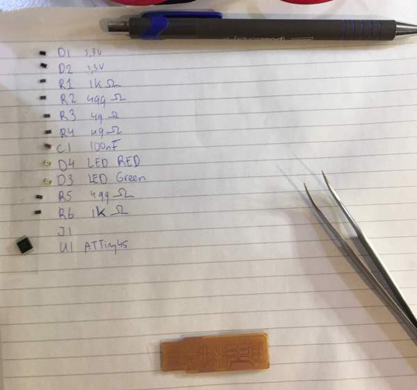
Get your components, use a tweezer to pick up the components and determine what your are going to place first and the position of the components.
Solder from low to high and from the center to the sides and consider harder to solder versus easy to solder components.
It can help to take a piece of paper and place the components in order of placement and write on the paper the component and identifier on your board design. Or event to print your board design and place the components on the print.
- Clean the board using soap and stick it to a surface your board can rest on using double sided tape.
- Get your solder iron and use a small tip that is fitted for SMD components.
- Turn the solder iron on and keep it on 70%. (Waag specific setting for the solder iron Weller WES51, look up the preferred heat for your solder. It will probably be around 300 degrees.)
- Clean your solder iron tip using a wet spons or by brushing the tip over special
- Place a little solder on the iron tip
- Place your tip at the place where you want to solder.
- Add a little solder to the place were the solder should be. (This is called wetting the board??)
- Wait until the solder starts flowing.
- “Glue” your component to the board by placing your component at the correct position and remove the iron. If it is not correctly placed, reheat the solder and move the component.
- When the component is placed correctly add the amount of solder needed and shortly wait till it is done flowing.
- Remove the tip and notice your solder drying as a shiny small blob. If it is not shiny, but grainy either your solder iron is not correctly calibrated, or you did not wait long enough for the solder to correctly flow.
- Repeat the soldering steps for the other legs of the components or new components.
- When finished soldering turn of the solder iron and check your board for shorts and wash your hands.
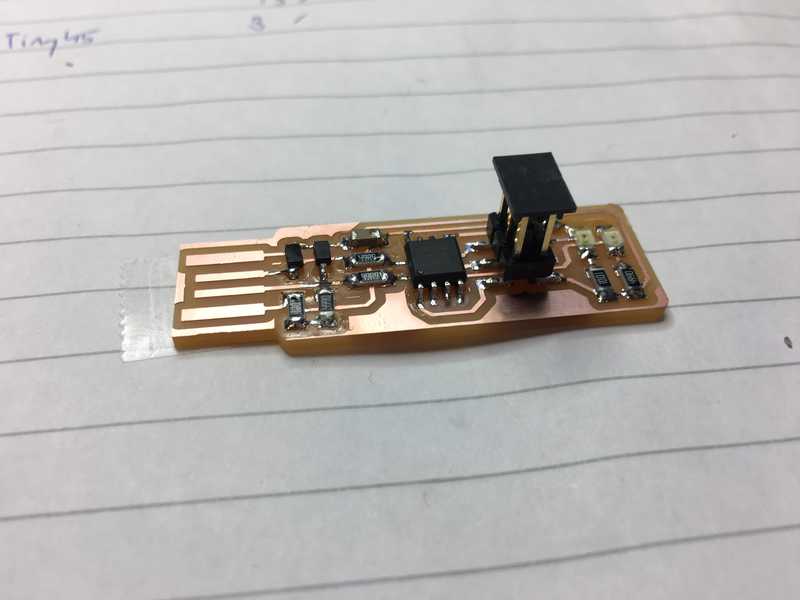
For the programming board I used the following steps. I worked from left to right and top to bottom in this case, in stead of from center to the corners. This is because, this board design allows for an easy flow from left to right and I am right handed. Also it allows me to first practice soldering with some easier components are resistors before getting to the ATTiny.
- Place the resistors.
- Place the diodes. Diodes have an orientation for their current flow, this is indicated with a small stripe at one side. The side with the stripe is the minus side. Make sure the side is in line with your design.
- Place the ATTiny45 by first ‘glueing’ one leg to the board and than solder the other legs to the board.
- Place the LEDs. Before placing the LED you should check if it is working and if it is the correct color. This LED has a green line that indicates the minus side. Use your multimeter to flow some current through the LED and check if it is working.
- Next I soldered the cut of the board together.
- Place the 6 header pins.
- Cut the extra copper from the USB connector tracelines and place solder on the tracelines to let is work with a USB plug. To make the solder on the tracelines working correctly I made it flat using a metal file.
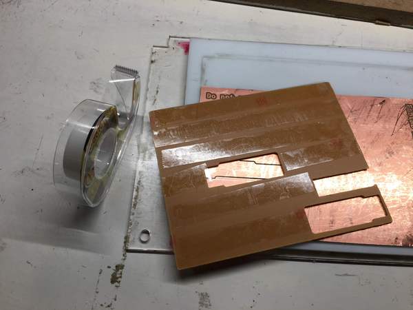
- I was now finished will soldering so I placed some tape at the bottom of the board to make the USB plug part thick enough for it to stick in a USB connector.
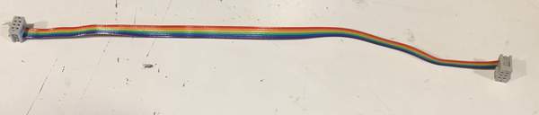
Creating a 6-pin connector ribbon cable
To be able to transfer data from a programmer to the newly created board we need a cable that connects the two. We are going to create 6-pin connector ribbon cable that can be used to connect two 6 pin male headers. For creating a 6-pin connector ribbon cable we need:
- a flat 6 lines ribbon cable
- 2 6-pin female ribbon cable connectors
- a bench press
- a wire cutter
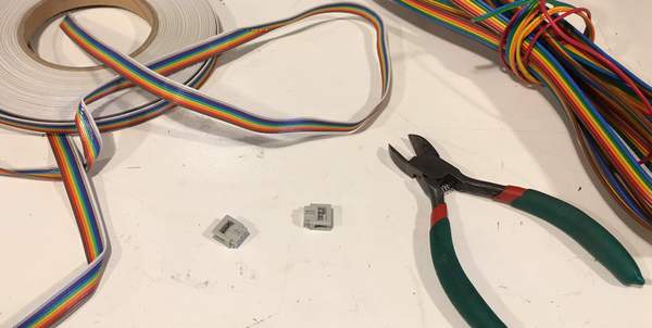
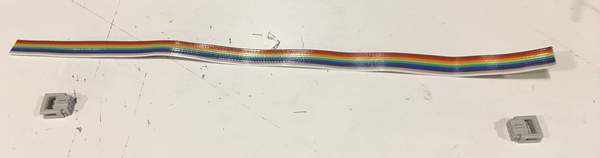
- Cut the cable in the correct length. Depending on your use case a length between 20 and 30 cm is most of the times fine. The longer the cable the most likely you get cable breaks. To short makes it difficult to connect two boards together. Note: In my case I had only 9 lines ribbon cable, so I first had to strip off 3 lines.
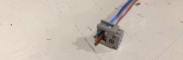
- Place your cable about in the header part that is made to connect a ribbon cable. Let it stick out a little bit for the connector to allow pressure.
- Make sure the cable is aligned with the blades and close the connector with your hands. Be careful with placing the connector, one it is in place it is difficult to remove. When trying to remove a connector, I often break the little legs.
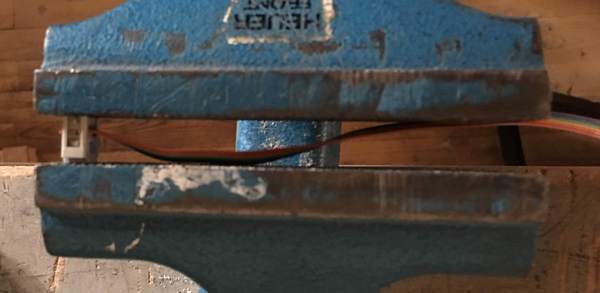
- Next put your connector with cable in the bench press, and slowly turn until the connector is fully closed. Check your connector against the light to see if it is fully closed.
- Repeat step 2 till 4 for the other end. But before you place the connector determine the orientation of your connector. Do you want the connectors to be mirrored or parallel. In my case they should be parallel.
Loading firmware on the board
When you finished soldering the board, you can load the firmware on the board. You need a programmer to be able to load your firmware on your board. For installing the firmware we followed the tutorial at: http://fab.cba.mit.edu/classes/863.16/doc/projects/ftsmin/index.html
- Connect your board with the programmer. Make sure you connect them in parallel.
- Download the firmware for the board and the software to use to upload the firmware from the site http://fab.cba.mit.edu/classes/863.16/doc/projects/ftsmin/index.html
- Configure the software for the correct chip: ATTiny45.
- Open a new Terminal and build the software.
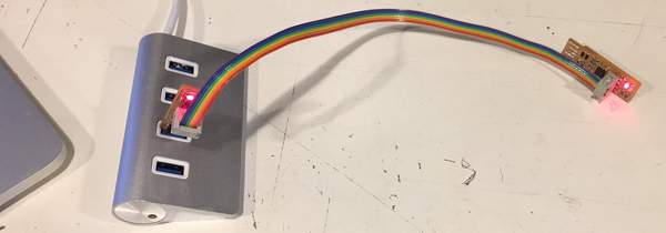
- Connect to programmer to your computer and start the software. Note: Our programmer was only USB-2 compatible, if you have a computer with only USB-3 ports you need to use a USB-hub.
- If everything went as plan, you see the firmware is uploaded to your new board with an output something like this.
C02KR0SBFFRP:fts_firmware_bdm_v1 biejh$ make flash
avrdude -p attiny45 -c usbtiny -P usb -e \
		-U flash:w:fts_firmware.hex

avrdude: AVR device initialized and ready to accept instructions

Reading | ################################################## | 100% 0.00s

avrdude: Device signature = 0x1e9206
avrdude: erasing chip
avrdude: reading input file "fts_firmware.hex"
avrdude: input file fts_firmware.hex auto detected as Intel Hex
avrdude: writing flash (2488 bytes):

Writing | ################################################## | 100% 2.65s

avrdude: 2488 bytes of flash written
avrdude: verifying flash memory against fts_firmware.hex:
avrdude: load data flash data from input file fts_firmware.hex:
avrdude: input file fts_firmware.hex auto detected as Intel Hex
avrdude: input file fts_firmware.hex contains 2488 bytes
avrdude: reading on-chip flash data:

Reading | ################################################## | 100% 4.00s

avrdude: verifying ...
avrdude: 2488 bytes of flash verified

avrdude: safemode: Fuses OK (H:FF, E:DF, L:62)

avrdude done.  Thank you.
If you receive an error there is something wrong. Check the correcting mistakes section.
- Next we set the fuses on the device to allow it to function as a USB connected device and later disable the reset pin. First we need to make sure everything works by running the command ‘make fuses’.
C02KR0SBFFRP:fts_firmware_bdm_v1 biejh$ make fuses
avrdude -p attiny45 -c usbtiny -P usb \
		-U lfuse:w:0xE1:m -U hfuse:w:0xDD:m \
		-U efuse:w:0xFF:m

avrdude: AVR device initialized and ready to accept instructions

Reading | ################################################## | 100% 0.01s

avrdude: Device signature = 0x1e9206
avrdude: reading input file "0xE1"
avrdude: writing lfuse (1 bytes):

Writing | ################################################## | 100% 0.01s

avrdude: 1 bytes of lfuse written
avrdude: verifying lfuse memory against 0xE1:
avrdude: load data lfuse data from input file 0xE1:
avrdude: input file 0xE1 contains 1 bytes
avrdude: reading on-chip lfuse data:

Reading | ################################################## | 100% 0.00s

avrdude: verifying ...
avrdude: 1 bytes of lfuse verified
avrdude: reading input file "0xDD"
avrdude: writing hfuse (1 bytes):

Writing | ################################################## | 100% 0.01s

avrdude: 1 bytes of hfuse written
avrdude: verifying hfuse memory against 0xDD:
avrdude: load data hfuse data from input file 0xDD:
avrdude: input file 0xDD contains 1 bytes
avrdude: reading on-chip hfuse data:

Reading | ################################################## | 100% 0.00s

avrdude: verifying ...
avrdude: 1 bytes of hfuse verified
avrdude: reading input file "0xFF"
avrdude: writing efuse (1 bytes):

Writing | ################################################## | 100% 0.00s

avrdude: 1 bytes of efuse written
avrdude: verifying efuse memory against 0xFF:
avrdude: load data efuse data from input file 0xFF:
avrdude: input file 0xFF contains 1 bytes
avrdude: reading on-chip efuse data:

Reading | ################################################## | 100% 0.00s

avrdude: verifying ...
avrdude: 1 bytes of efuse verified

avrdude: safemode: Fuses OK (H:FF, E:DD, L:E1)

avrdude done.  Thank you.
- Disconnect your board from the programmer and plug it in a USB port and check if the computer recognizes your board as a USBTiny. You can see the difference in your output without and with our USBTiny board.
C02KR0SBFFRP:fts_firmware_bdm_v1 biejh$ ioreg -p IOUSB
+-o Root  <class IORegistryEntry, id 0x100000100, retain 15>
  +-o Root Hub Simulation Simulation@14000000  <class AppleUSBRootHubDev$
    +-o Apple Internal Keyboard / Trackpad@14400000  <class AppleUSBDevi$
    +-o BRCM20702 Hub@14300000  <class AppleUSBDevice, id 0x10000364f, r$
    | +-o Bluetooth USB Host Controller@14330000  <class AppleUSBDevice,$
    +-o USB2.0 Hub@14200000  <class AppleUSBDevice, id 0x100003e10, regi$
    +-o USB3.0 Hub@14600000  <class AppleUSBDevice, id 0x100003e2a, regi$
C02KR0SBFFRP:fts_firmware_bdm_v1 biejh$ ioreg -p IOUSB
+-o Root  <class IORegistryEntry, id 0x100000100, retain 15>
  +-o Root Hub Simulation Simulation@14000000  <class AppleUSBRootHubDev$
    +-o Apple Internal Keyboard / Trackpad@14400000  <class AppleUSBDevi$
    +-o BRCM20702 Hub@14300000  <class AppleUSBDevice, id 0x10000364f, r$
    | +-o Bluetooth USB Host Controller@14330000  <class AppleUSBDevice,$
    +-o USB2.0 Hub@14200000  <class AppleUSBDevice, id 0x100003e10, regi$
    | +-o USBtinySPI@14210000  <class AppleUSBDevice, id 0x100004013, re$
    +-o USB3.0 Hub@14600000  <class AppleUSBDevice, id 0x100003e2a, regi$
- If everything worked reconnect your board to the programmer and run the command ‘make rstdisbl’ to disable the reset pin.
C02KR0SBFFRP:fts_firmware_bdm_v1 biejh$ make rstdisbl
avrdude -p attiny45 -c usbtiny -P usb \
		-U lfuse:w:0xE1:m -U hfuse:w:0x5D:m \
		-U efuse:w:0xFF:m

avrdude: AVR device initialized and ready to accept instructions

Reading | ################################################## | 100% 0.00s

avrdude: Device signature = 0x1e9206
avrdude: reading input file "0xE1"
avrdude: writing lfuse (1 bytes):

Writing | ################################################## | 100% 0.00s

avrdude: 1 bytes of lfuse written
avrdude: verifying lfuse memory against 0xE1:
avrdude: load data lfuse data from input file 0xE1:
avrdude: input file 0xE1 contains 1 bytes
avrdude: reading on-chip lfuse data:

Reading | ################################################## | 100% 0.00s

avrdude: verifying ...
avrdude: 1 bytes of lfuse verified
avrdude: reading input file "0x5D"
avrdude: writing hfuse (1 bytes):

Writing | ################################################## | 100% 0.01s

avrdude: 1 bytes of hfuse written
avrdude: verifying hfuse memory against 0x5D:
avrdude: load data hfuse data from input file 0x5D:
avrdude: input file 0x5D contains 1 bytes
avrdude: reading on-chip hfuse data:

Reading | ################################################## | 100% 0.00s

avrdude: verifying ...
avrdude: 1 bytes of hfuse verified
avrdude: reading input file "0xFF"
avrdude: writing efuse (1 bytes):

Writing | ################################################## | 100% 0.00s

avrdude: 1 bytes of efuse written
avrdude: verifying efuse memory against 0xFF:
avrdude: load data efuse data from input file 0xFF:
avrdude: input file 0xFF contains 1 bytes
avrdude: reading on-chip efuse data:

Reading | ################################################## | 100% 0.00s

avrdude: verifying ...
avrdude: 1 bytes of efuse verified

avrdude: safemode: Fuses OK (H:FF, E:5D, L:E1)

avrdude done.  Thank you.
- Last you can remove the solder bridge you put on the board to fuse two lines. You can desolder it (see correcting solder mistakes section), or carefully remove it with a knife.
Using solder as glue
- Place a little solder on the tip of the component you want to solder or on the part of the board you want to solder.
- Place the component at the desired place.
- Heat one leg with your solder iron and then let the little bit of solder dry.
- Your component is now not fully soldered, but connected to your board, making it easy to solder all the legs.
Correcting mistakes
You might made a solder mistake, placed a component in the wrong orientation, used a wrong or faulty component, a faulty wire, do not have a proper wire or USB connection.
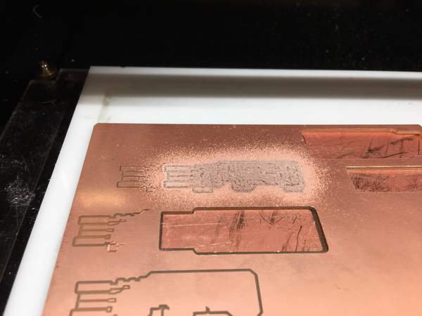
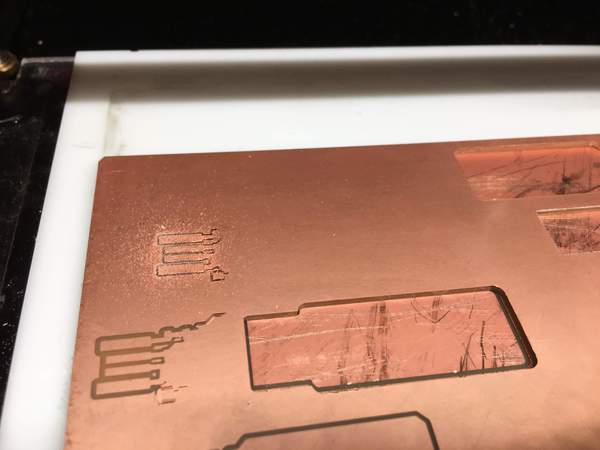
Milling but no trace lines
If your device is milling but you do not see the tracelines, there is an error. Check if you have the correct cut dept, you placed the mill bit correctly and if your bit is not broken. If this is all not the problem, you might have not placed your copper plate perfectly flat. In my case the copper plate was maybe a little bit bended because it had been placed and removed twice already. I maybe could have corrected this by putting more pressure on the plate when applying it to the bed.
Milling but lots of noise
If your mill is making more those than usual, it is an indication the drill bit is having to much pressure. This can be an incorrect cut dept, speed, or wrongly placed bit. I had this problem, and initially my problem was a speed of 1 instead of 4. we checked the pin placement, speed and cut dept, this all seems to be correct. Still the noise problem remained. We reset the device and recalculated the G-code, this did not work, we still got the high noise. I decided to still go ahead and ended up with a nice cut. In my case I remained with the question what caused the high noise.
Checking your circuit for faults
It might be that milling gave a small error in your circuit, or milling went fine, but you made an error in your circuit design.
- Take a look at your board, look if you see execs material that should not be there, if lines are connected that should not be connected, or if there are lines that are not connected at all (floating lines)
- Carefully remove the material that should not be there.
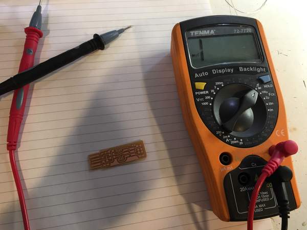
- If this checks out, use the multimeter to check for shorts (connections that should not be present) and floating lines ( lines that are not connected)
- Turn the multimeter on and place the setting to “beep”.
- The beep is when you have a connection between the + and -.
- For example you can check your longest traces of your board, or traces where you think might be something wrong.
Correcting solder mistakes
You might by accident have used to much solder, or soldered a part at a wrong place. Also with SMD components you might have made a short by letting solder flow under your component. You can remove solder by desolder wire or heat gun.
Using desolder wire
- Heat the solder with your solder iron.
- Place desolder wire at the solder and it will flow at the wire.
- If it does not stick to the wire, try adding a little more solder making it easier for the solder to attach to the wire. Be careful, do not do as I and let the wire slip on your board.
Using the heating gun to remove a component
Note that the tip of the heat gun falls of easily.
- Turn it on and wait till it is warm.
- Aim the tip of the heater at your component and wait till you see the solder is getting wet.
- Take your tweezer and remove the component that is wrongly placed.
- Place the heat gun back and turn it off.
Correcting board design mistakes
If you by made a circuit design mistake, try to correct is using wires. Use small wires, do not make them much longer than the distance, they need to bridge.
Error with compiling the firmware.
C02KR0SBFFRP:fts_firmware_bdm_v1 biejh$ make
avr-gcc -mmcu=attiny45 -Wall -DF_CPU=16500000UL -I. -funsigned-char -funsigned-bitfields -fpack-struct -fshort-enums -Os -Iusbdrv -c main.c -o main.o
make: avr-gcc: No such file or directory
make: *** [main.o] Error 1
In this case we were missing the avr-gcc. We check if the install went correctly, this was the case. Still the Terminal did not detect the software. In this case the terminal path settings were not updated. Closing and opening a new terminal window will allow the terminal to load the new path settings.
You can also add the new path to the avr-gcc manually, if your terminal still does not recognize the application after a restart, but for me opening a new terminal window did the trick.
C02KR0SBFFRP:fts_firmware_bdm_v1 biejh$ make
avr-gcc -mmcu=attiny45 -Wall -DF_CPU=16500000UL -I. -funsigned-char -funsigned-bitfields -fpack-struct -fshort-enums -Os -Iusbdrv -c main.c -o main.o
main.c:109:13: warning: always_inline function might not be inlinable [-Wattributes]
 static void delay ( void )
             ^
avr-gcc -mmcu=attiny45 -Wall -DF_CPU=16500000UL -I. -funsigned-char -funsigned-bitfields -fpack-struct -fshort-enums -Os -Iusbdrv -c usbdrv/usbdrv.c -o usbdrv/usbdrv.o
avr-gcc -mmcu=attiny45 -Wall -DF_CPU=16500000UL -I. -funsigned-char -funsigned-bitfields -fpack-struct -fshort-enums -Os -Iusbdrv -c usbdrv/oddebug.c -o usbdrv/oddebug.o
avr-gcc -x assembler-with-cpp -mmcu=attiny45 -Wall -DF_CPU=16500000UL -I. -funsigned-char -funsigned-bitfields -fpack-struct -fshort-enums -Os -Iusbdrv -c usbdrv/usbdrvasm.S -o usbdrv/usbdrvasm.o
avr-gcc -mmcu=attiny45 -o fts_firmware.elf main.o usbdrv/usbdrv.o usbdrv/oddebug.o usbdrv/usbdrvasm.o
avr-size -C --mcu=attiny45 fts_firmware.elf
AVR Memory Usage
----------------
Device: attiny45

Program:    2488 bytes (60.7% Full)
(.text + .data + .bootloader)

Data:         75 bytes (29.3% Full)
(.data + .bss + .noinit)


avr-objcopy -j .text -j .data -O ihex fts_firmware.elf fts_firmware.hex
Error with uploading the firmware
If you receive an error like this
C02KR0SBFFRP:fts_firmware_bdm_v1 biejh$ make flash
avrdude -p attiny45 -c usbtiny -P usb -e \
		-U flash:w:fts_firmware.hex
avrdude: Error: Could not find USBtiny device (0x1781/0xc9f)

avrdude done.  Thank you.

make: *** [flash] Error 1
The computer cannot detect your connected device. Debug advice: Check if your installed all the software, your board is properly connected, if the cables you are using are working and if your computer can detected the board. If everything on the computer and connected aspect checks out you are left with a hardware problem. Recheck if your board and programmer do not have any faulted connections or faulty components.
In our case the board was properly connected and we had no cable problems. We checked if the board was detected by the computer. It was not.
C02KR0SBFFRP:fts_firmware_bdm_v1 biejh$ ioreg -p IOUSB
+-o Root  <class IORegistryEntry, id 0x100000100, retain 15>
  +-o Root Hub Simulation Simulation@14000000  <class AppleUSBRootHubDev$
    +-o BRCM20702 Hub@14300000  <class AppleUSBDevice, id 0x100002b1a, r$
    | +-o Bluetooth USB Host Controller@14330000  <class AppleUSBDevice,$
    +-o Apple Internal Keyboard / Trackpad@14400000  <class AppleUSBDevi$
For us it turned out our board only works on USB-2 and our computer only had USB-3 ports. Using a USB-hub solved the problem.
C02KR0SBFFRP:fts_firmware_bdm_v1 biejh$ ioreg -p IOUSB
+-o Root  <class IORegistryEntry, id 0x100000100, retain 15>
  +-o Root Hub Simulation Simulation@14000000  <class AppleUSBRootHubDev$
    +-o Apple Internal Keyboard / Trackpad@14400000  <class AppleUSBDevi$
    +-o BRCM20702 Hub@14300000  <class AppleUSBDevice, id 0x10000364f, r$
    | +-o Bluetooth USB Host Controller@14330000  <class AppleUSBDevice,$
    +-o USB2.0 Hub@14200000  <class AppleUSBDevice, id 0x100003b1c, regi$
    | +-o USBtinySPI@14240000  <class AppleUSBDevice, id 0x100003b80, re$
    +-o USB3.0 Hub@14600000  <class AppleUSBDevice, id 0x100003b37, regi$