10. Molding and casting
This weeks group assignment is to review the safety data sheets for each of your molding and casting materials, then make and compare test casts with each of them. For the individual assignment of this week we should design a 3D mold around the stock and tooling that you’ll be using, mill it, and use it to cast parts
Files, planning and tools
This week I was away on a planned trip therefore it took me a bit longer to catch up.
Files
Planning
- Watching the lecture of Neil
- Getting the right information from the group for the group assignments
- Do some tests for casting materials myself
- Making a 3D design of the object I want to cast.
- Making the design for my mold
- Casting my mold.
- Trying out some tests for my final project.
Tools
- Shopbot
- Fushion 360
- Illustrator
- Partworks 3D
Link with final project
For this week I wanted to make a leaf, again. However different than the experiments in the other weeks for this week I wanted to create a mold that I can use for my final project. One of my ideas for my final project is to create leaves with glass fiber or PMMA inside the leaf. I will use this to light up each leaf and this way I don’t need any electronics inside the leaves. I hope to produce a more modular design this way.
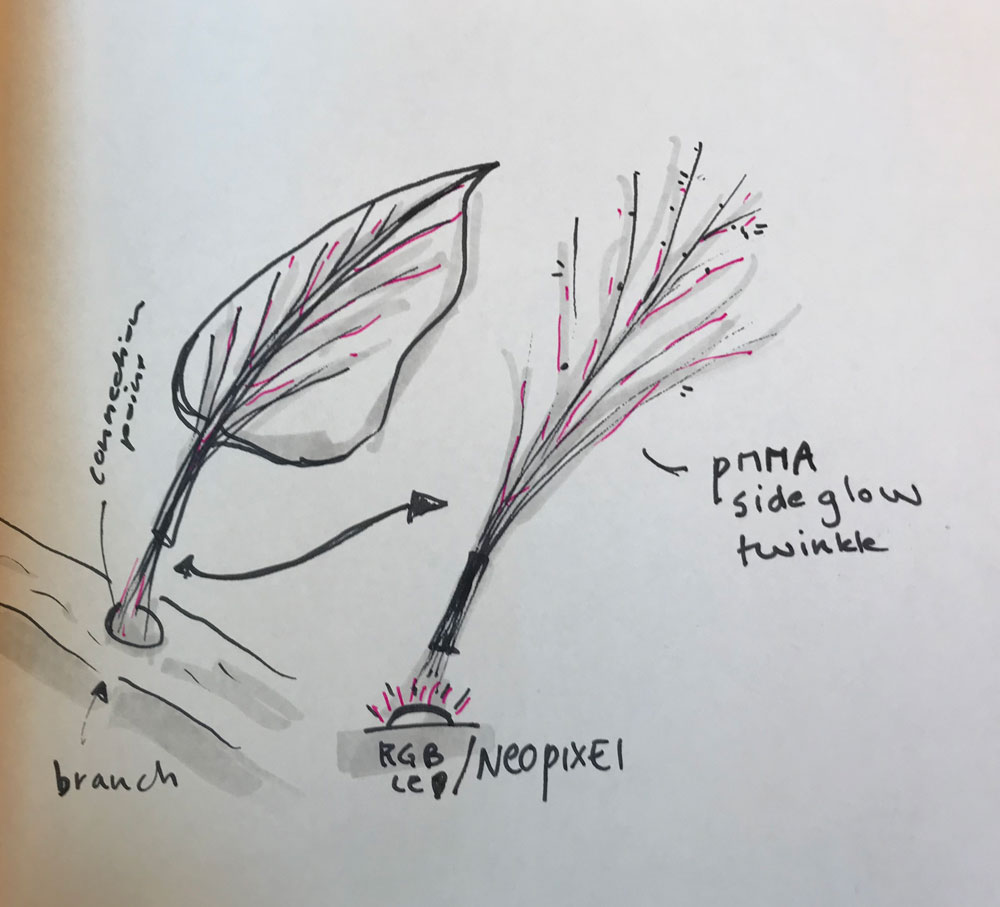 Each leaf will have PMMA fiber connection with RGB-LED
Research and inspiration
For this assignment I researched a lot on how to create veins in a 3D leaf. In the end this took too long for my 3D-skills to include. I also looked a lot into to documentation of Anne and to the tutorial from the Fabacademy on how to create and design the mold around my stock. I wanted to use the Fushion 360 CAM therefore I also looked into some tutorials how to use CAM and how it works. In the end I decided to use Partworks 3D instead mainly due to the amount of time I had.
Links used for design leaf
links used for mold design
links used for CAM
- Fusion 360 CAM for CNC Beginners
- Optimizing toolpath generation in Fusion 360 and HSM CAM by Autodesk
What we did – Group assignment step-by-step
As group assignment we had to read the safety instruction datasheet and we had to do some tests. I wasn’t there when the group did this assignment. Therefore I will cast two different material as test myself, Rutger helped me with the different tests and showed me the datasheets of the material used.
It’s always important to first read the datasheet to make sure you take the right safety preconditions. In the datasheets you can find the ‘Hazardous materials identification system’ (HMIS), this is a system that checks materials and gives information on four criteria: Health, Flammability, physical hazard and personal protection. More detailed information can found on the Wikipedia page HMIS-system.
 HMIS safety indication system
As you can see in this image for each of the specific criteria the HMIS gives information on the safety level from level 0: ‘Minimal Hazard’ to level 4: ‘Severe Hazard’. Based on these levels specific safety measure should be taken.
Datasheets
- Wikipedia on HMIS
- Chem Safety Pro on HMIS
- Smooth-on Vytaflex-50
- Smooth-on, Vytaflex-50 datasheet
- Silicones and more: Transparent 40
What I did – step-by-step
Step 1: Designing the leaf
The last couple of weeks I designed different leaves for the Fabacademy as practice for my final project. I could reuse some of these designs. However I also wanted to create a mold with a lot of detail and I wanted to create a more complex leaf-shape. My main goal way to add the veins in a 3D-model. I experimented with Illustrator and image trace.
 Image trace veins leaf
However I didn’t manage to combine this with my leaf design in Fushion due to my level of 3D design skills and the time I had. Therefore I decided to just design the leaf with the petiole without the veins. Keeping it simple. Steps I took.
- Use drawing from Illustrator file I previous used for the Input Devices week.
- Extrude the leaf.
- Image trace in Illustrator, save as DXF and extrude in Fushion, however this didn’t work. I made Fushion really slow and it didn’t have a nice extrude.
- Use the patch workspace to bend the leaf.
- Use a loft to create the petiole
- Combine the two.
- I made a nice 3D shape of a leaf however Henk mentioned I should make a mold that’s flat as that’s a lot easier. This was a shame because it took me a lot of time to design the leaf the way I wanted it to be and now I had to redesign it to make in simple while I didn’t have much time. So I decide to lay the leaf flat however the petiole still has a curve as it took me really long to create this design.
- The first extrude of the leaf is flat, I still had this leaf as a body. So I used this body as my leaf and combined it with the petiole I already designed.
- I had to change the angle of the petiole to make fit realistically with the flat leaf.
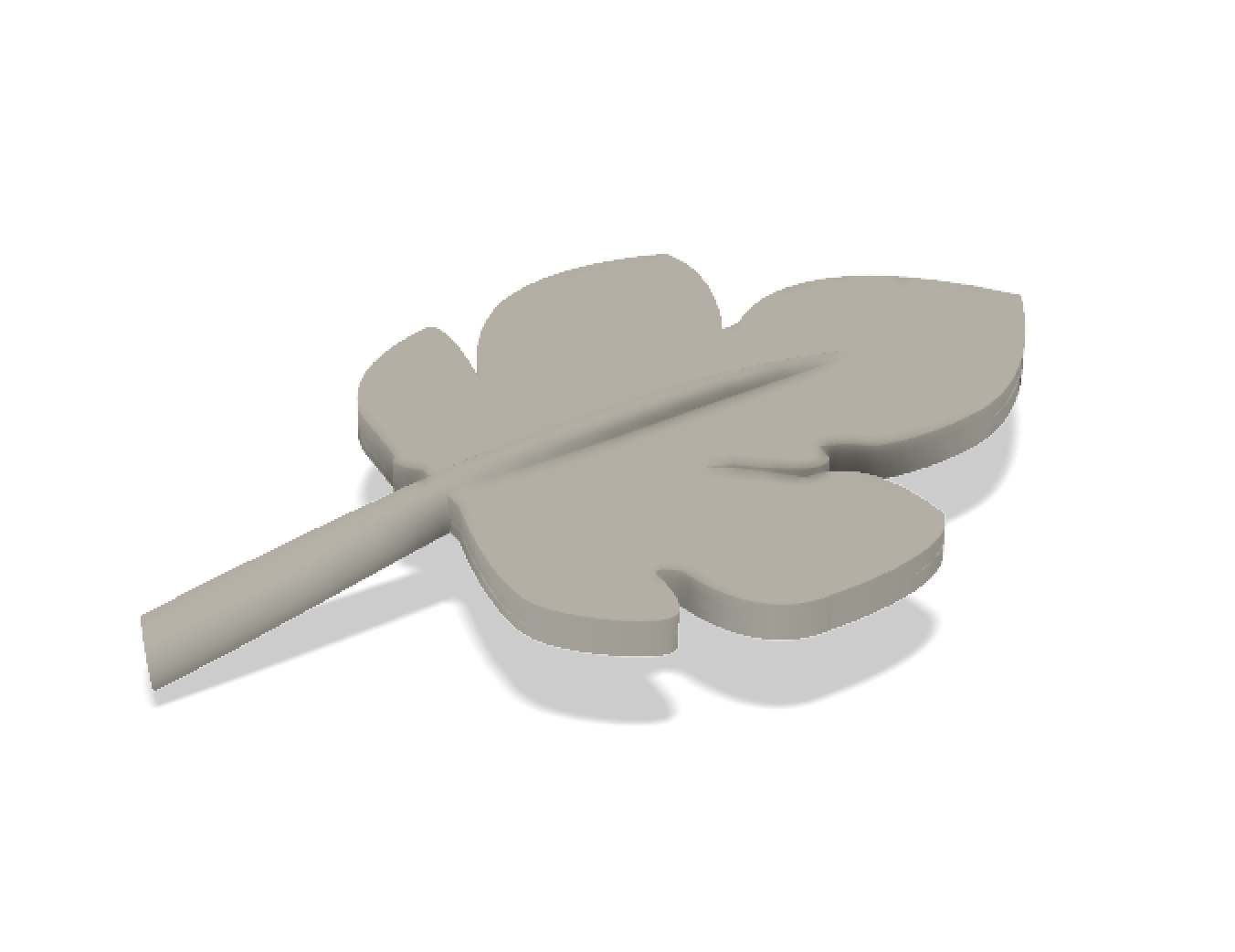 End result 3D-design leaf, stock for molding and casting
Step 2: Making the mold design
The design of my mold took a lot longer than I thought. I wanted to use the nested mold method as Neil mentioned in his lecture as the best way for a nice cast. In addition, Anne did this in week 10 and it looked a lot more solid and precise than using markers for placement. Therefore I used Anne’s documentation to figure out how this would work for my stock. The basic steps I took in Fushion 360 to create my mold.
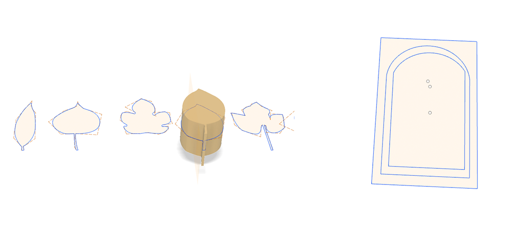 left sketch: extrude from Illustrator file, right sketch:sketch used for design mold
- Create a new sketch
- Draw a rectangle the size of the material. This will represent the wax-block I will use.
- Draw the shape of the outside of the mold within the rectangle representing the material.
- Draw the shape of the inside of the mold within the rectangle and within the outside.
- Finally place the leaf in the middle of it all.
- Slice the 3D-design of the leaf, using slice body and a line following the shape of the leaf, in half.
- Extrude the inside part and extrude this to a full body. And use the same slice as the leaf for this body.
- Now we have two parts, each will be a mold.
- For mold 1 I used only the inside which I subtracted from the full material.
- For mold 2 I also used the space in between the outside and inside part to subtract it from the material and to subtract it from the inside mold. This way I can nest mold 1 in mold 2.
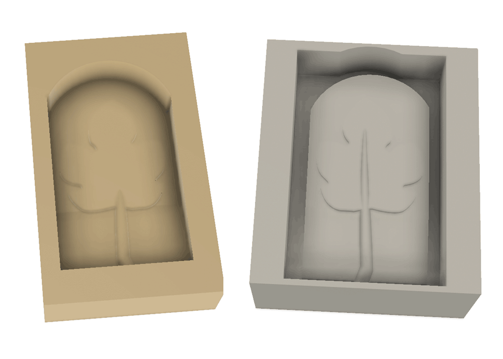 End result 3D-design both molds; left mold 1 and right mold 2
Step 3: Setting the toolpaths
First I used the Fushion Cam tool. however in the end I didn’t use this version. Because it took me longer to figure out how I could set the rough and finish toolpaths in comparison with pathworks 3D.
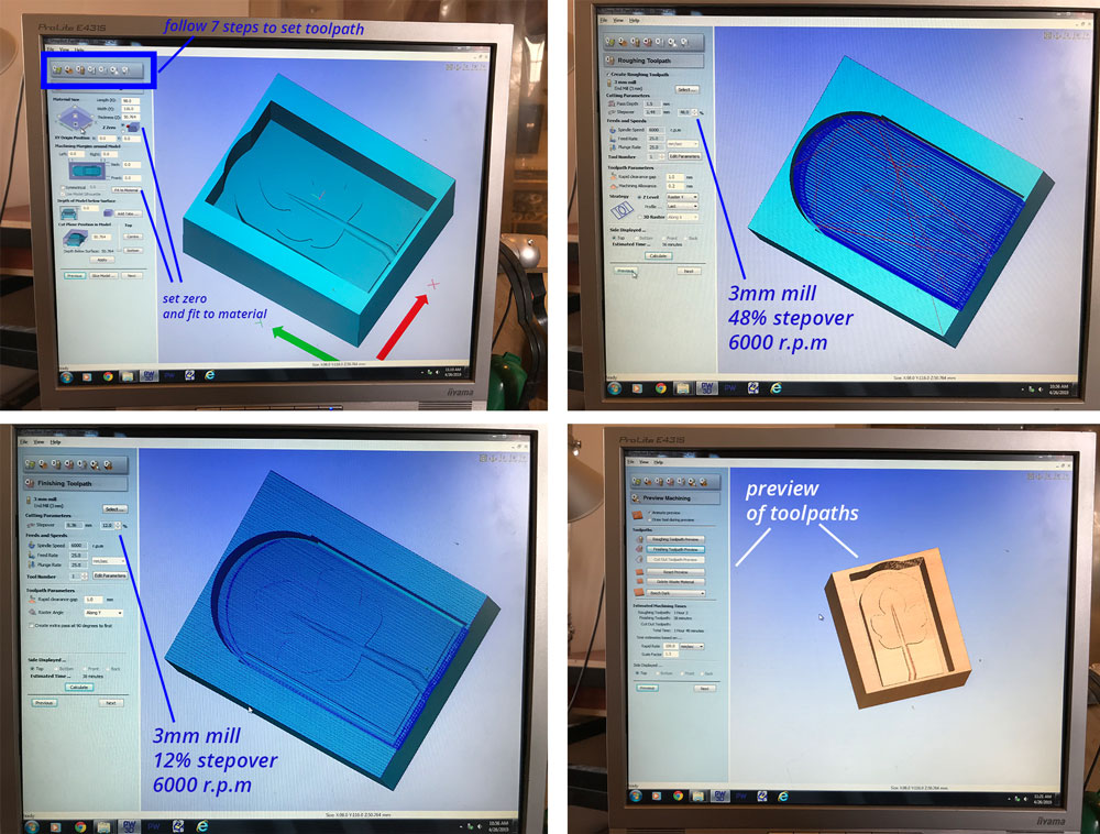
- Orientate and size Model: Select file to mill, and select the top surface. For mold 1 it’s bottom and mold 2 it’s top. It also shows the model size, you can double check this with your design.
- Material size and margins: This section shows the size of the design and you can set the size of the material and how the design is placed in the material. I set the size the same as the material and I don’t need an offsets or margins around it because I designed my mold including the material. So I selected for both molds fit to material. Make sure to set the Zero on top and on a corner.
- Roughing toolpath: For the roughing toolpath I’ll use the 3mm mill. The step over is set to 48%, speed to 6000 rpm, feed and plunge to 25 mm/sec. Press calculate to calculate the time.
- Finishing toolpath: I will use the same mill for the finish, also a 3mm mill. Step over is set to 12%, speed stays at 6000 rpm, and feed and plunge stay at 25 mm/sec. Press calculate to find out how long this will take.
- Cut out toolpath: I can skip this section as I won’t be cutting out parts.
- Preview machining: This shows a preview of the roughing and finishing toolpath. This can be used to double check the design. If it doesn’t look like you though, change the 3D-design and start over with setting the toolpaths.
 Setting the toolpaths of my molds
Step 4: Milling the mold
After I set the toolpaths I can start milling.
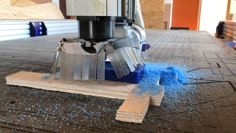
- Place to mold: use double sided tape and wood to make sure your material won’t move while milling.
- Set the X,Y,Z axis as we did in week 8 with computer controlled machining.
- For milling wax we don’t turn on the dust collector, because we want to reuse the left over material.
- Start the machine, make sure to set the speed on 6000 rpm.
- When it’s done, collect the left over wax in a bag. This is used to make new molds again.
 Milling my mold
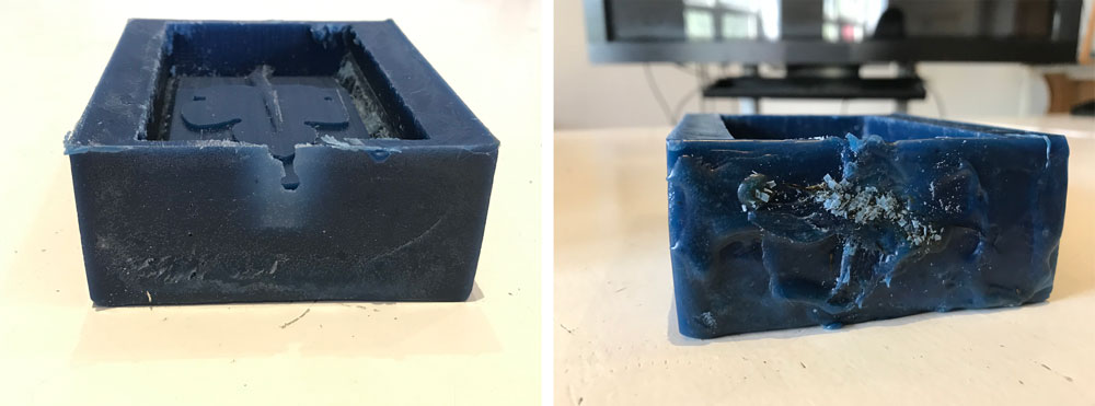
Step 5: Fixing my mold 2
Because the first mold milling went wrong due to material failure, I had to use a different block of wax for my second mold. The dimensions of this block perfectly fitted the length of my design. I already thought this would be a too close fit. I fixed my mold with heating up some left over wax and placing some back onto my wax mold.
 fixing my mold to make sure it won’t leak
The end result doesn’t look nice but it works well! Now I’m able to cast my molds.
Step 6: Casting my molds
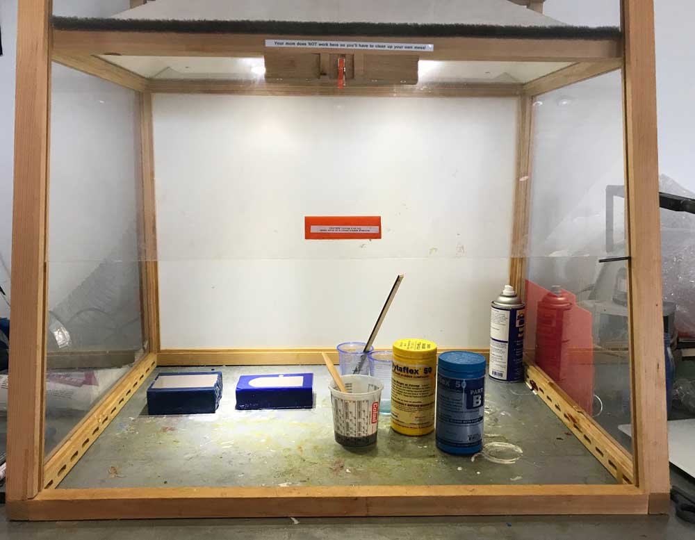
When my molds were finished I was able to cast them. In the end I casted it with two different material to see what the difference would be. I used Silicone Rubber and Transparent Silicone.
Casting Silicone Rubber
My first cast was with silicone Rubber, the Smooth on Vytaflex-50. The datasheet of the Vytaflex-50 can be found online: link to Vytaflex-50 datasheet. I worked in a well ventilated room and used gloves when working with the material.
 First cast of mold
Steps I took:
- Apply release agent to molds to make sure you can remove your mold afterwards. I used the universal release agent by Smooth-on.
- Make sure you know how much you need in total for you molds. For me this was 250 ml. You can test this by filling your molds with water and see how much it fill up with.
- There two components A and B. Make sure to double check what the mixing ratio is for the material you use. For the Vytaflex-50 it 1A:1B. So you use the same amount.
- After measuring the right amounts you can mix them together. Make sure you stir the material well enough before pouring.
- When the material is nicely and smoothly mixed you can pour the cast. Make sure not to include bubbles.
- Wait till it’s cured, for the vytaflex-50 it’s 16 hours I left it over night, and remove the molds for the end results.
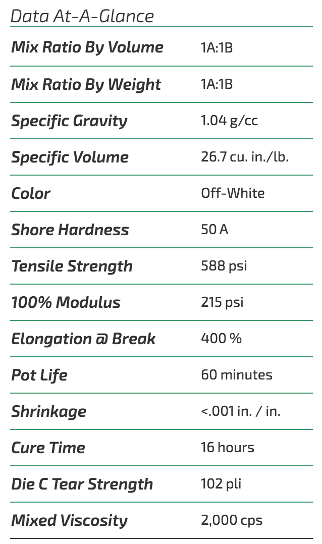 Technical data Vytaflex 50
The molds worked out nicely. Later on I used the same method to cast the leaf. For this I used the Vytaflex-50 as well. The end result is nice but I don’t like it enough to use it for my final project.
 Mold for leaf
Casting with Silione
I followed the same steps when I did a second cast with silicone transparent 40 by ‘silicones and more’. I read the datasheet. Made sure I had enough material. I followed the same steps as above. The mixing ratio of the silicones are different than the Vytaflex-50. Mixing ratio of the A and B components are 10:1 in stead of 1:1. As you can see in technical summary below:
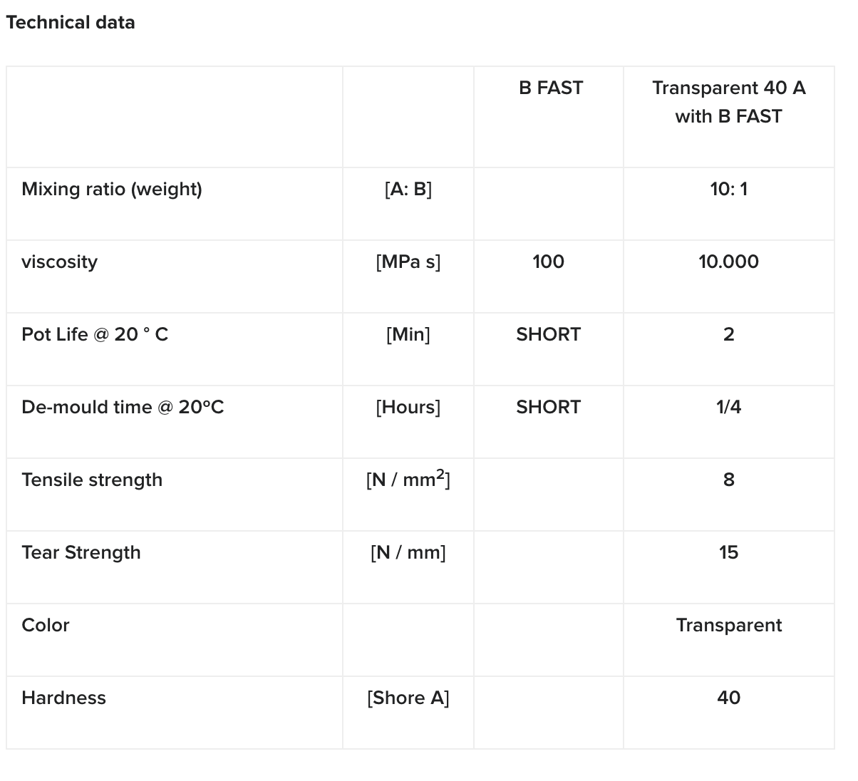 Technical summary of silicone 40
I casted the silicone molds at home at the same time I also casted the leaf with the Vytaflex-50.
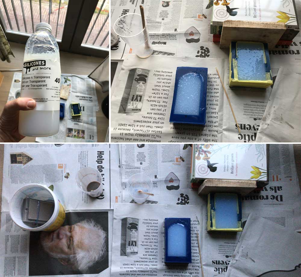 Casting the silicone mold
The casting went nicely. It gave a nice result and the advantage of the transparent mold is that the casting of the leaf must go easier. As I found it a bit difficult to see what I was doing while casting the leaf with the Vytaflex-50.
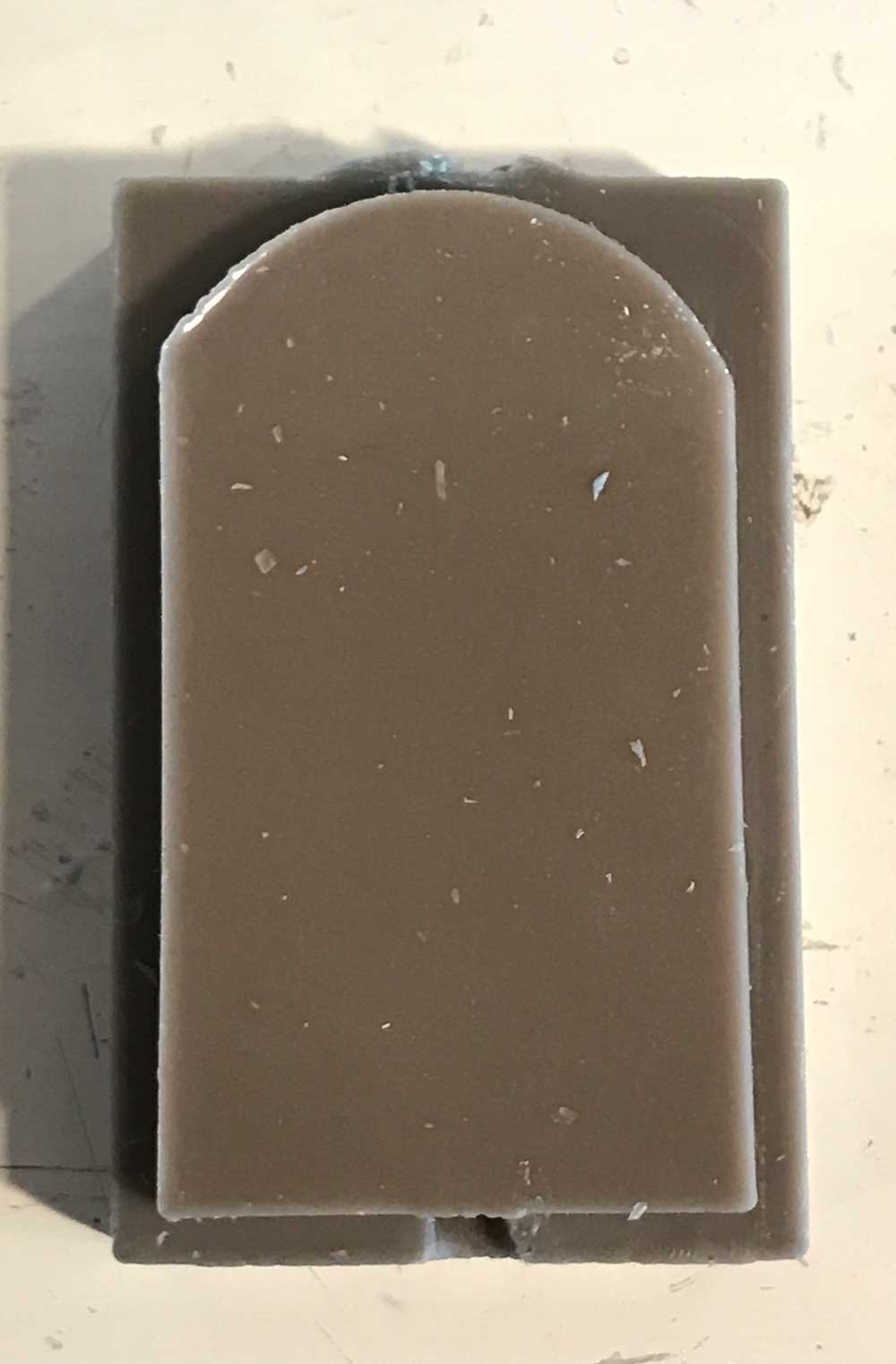
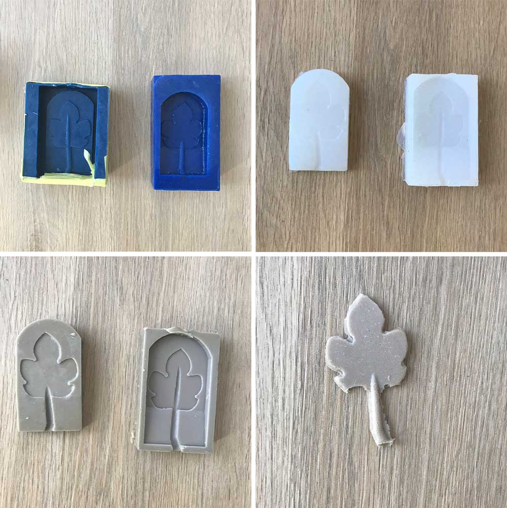 End result casts
What I did wrong – and how I solved it
I looked forward to this week however the design and milling process was a frustrating.
Bubble in the wax
When I milled my first mold the end result looked weird, the leaf was partially gone. Together with Rutger I tried to figure out what must have gone wrong. It could be the design, the machine or the material. My first guess was that there was something wrong with the material.
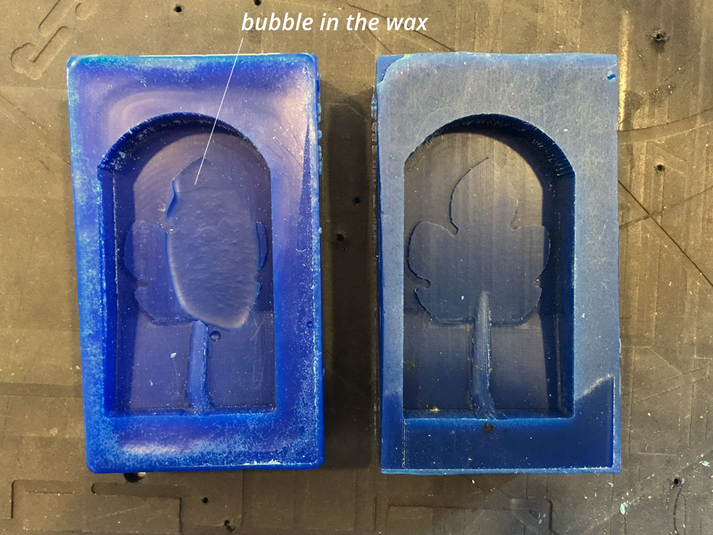 Failure with the use of wax
milled my first mold but when it was finished something went wrong. the end results wasn’t the way it showed on the toolpath menu in the CAM program. I looked at it with Rutger but we didn’t know what could be the problem. It could be my design, the machine or the material. First we double checked the design and the toolpaths. Both seemed fine on the screen. I double checked the preview of the toolpaths send to the machine and this didn’t show the problem. So to be sure I milled the same design with a different wax-block. This version turned out nicely. So it was the material, it had a bubble in it.
Didn’t think of the mill
Go back to the design of the leaf because I realized the mill is 3 mm. Therefore I needed to change some shapes and angles otherwise it wouldn’t have a nice finish.
Mold broke
As mentioned above my mold had a hole after milling it. After casting my first cast the wax-mold also broke when I wanted to remove it. However I still wanted to use it to cast a second version. To fix it I used good quality paint tape. This worked really well.
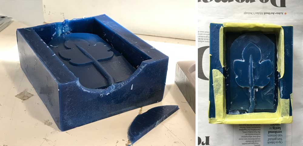 Second fix of wax mold
What I learned
Keeping the machine in mind while designing.
Neil mentioned it in his lecture, but I only really grasped the idea of it while designing. When designing for the shopbot make sure to keep the tooling in mind while designing. When I set the toolpaths for the first time I noticed that the mill wasn’t able get a nice finish everywhere. This was because I didn’t think of the right sizes and distances based on the mill I was using. I used a 3 mm mill and this means that details and distances should be at least 3mm. Therefore I redrew my design to make sure I get the right finish.
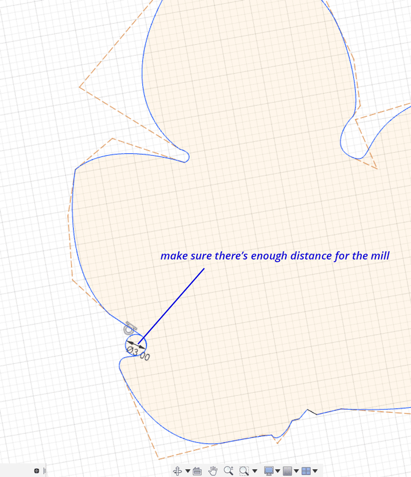 Keeping the mill in mind while designing
Casting leaves won’t work for my final project
I also learned that the way the leaves cast doesn’t give me the end result I want for my final project.
- It’s a bit too messy to totally control in the time I have.
- The result will look better when the petiole and the leaf are made from different material.
- It’s hard to control adding the optic fiber in this casting process.
- To really make sure this works for my final project, I should design a different mold because this version isn’t the best way to cast a mold. Because the pouring hole is too much on the side and the mold stands vertical while it’s being casted. It should be better horizontal.
Therefore I won’t use this technique for my final project.
What made me proud!
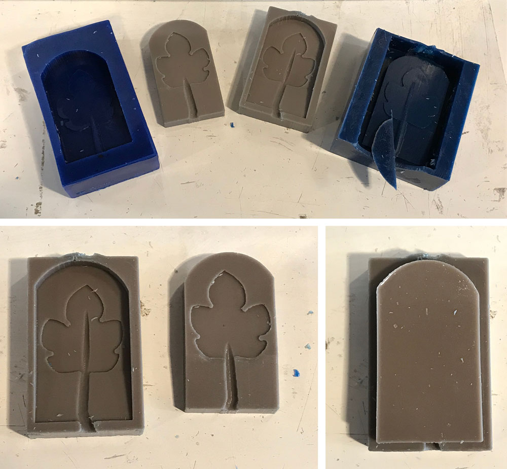
In the end I’m most proud of the nesting design. After I casted both molds, they fitted perfectly together.
 Nesting design of my molds works nicely
Credits and references
Because I was away for a week I wasn’t able to finish this assignment in week 10. It was a bit difficult to catch up as I missed the lesson on Thursday. Luckily Rutger helped me out a lot with the use of the machine and explained me the molding and casting. Anne helped me with the nesting design of the mold.