16. Interface and application programming
This week individual assignment is to write an application that interfaces with an input and/or output device that you made and the group assignment is to compare as many tool options as possible.
Files, planning and tools
Files
- Processing: compare python mode
- Processing: compare normal mode
- Processing: serial communication test
- Arduino: cleaned up Neopixel Strand test for serial interface
- Processing: serial write test
Planning
- Group assignment and its documentation
- Experimenting and figuring out how processing works
- Designing and building the interface for my Neopixel board
Tools
- Arduino IDE
- Processing
Link with final project
For this weeks assignment I want to get my Neopixel board to respond to various settings. For my final project I want the lights in the tree to be able to vary in colors based on themes like autumn, spring, summer, winter, night and day. For this week I want to write the program for my Neopixel board to be able to switch colors based on the theme, although for this week I try to keep it as simple as possible.
Research and inspiration
- Processing
- Python mode for processing
- Sparkfun tutorial on connecting Arduino to Processing
- Processing tutorial buttons
What we did – Group assignment step-by-step
For the group assignment of this week we have to compare as many tool options as possible. Adel, Julie, Madjid and Stéphan of the Paris Fab lab at the Sorbonne University were at the Waag this week because their university was closed, it was really nice to meet them in real life. We did the group assignment together Madjid worked on python. He explained the difference between the syntax of Python and Java, he already has experience with programming. Julie looked at and worked through the Arduino to processing tutorial by Sparkfun. She got this to work with an Arduino and a breadboard and the next step is to connect it to a self made board. Anne looked at example codes by processing and connected this to her board with a photo transistor from week 7. I did a similar assignment as Anne, only I was curious what the difference would be between the normal Java mode in processing and the Python Mode. So I looked at this difference. I describe my findings more in detailed below. And finally Joey looked at the difference in the setup of serial communication with Processing and Node.js. He elaborates more in detail on this subject in his documentation. The end results for our group assignment that I take away are:
- Python is a beautiful language but is more useful for this weeks assignment when you already have more programming experience like Madjid and Joey. I would love to get more experience with python it sounds nice.
- The Python mode in processing is quiet easy to work with, I really like the syntax. I tried this because I wanted to figure out how I could learn the syntax of python in an easy way. However for processing it probably still more wise to use the general mode because it provides more examples, tutorials, and documentation. In addition the setup of serial communication in python mode is a bit more difficult for a beginner.
- Node.js and Processing both work well with serial communication they both have a library that you can use for the setup.
- Processing is really easy for a beginner to get a visual interface in combination with a board. Anne, Julie and I got example codes running quite quickly. Therefore I decided to use processing for my assignment this week.
What I did – step-by-step
Step 1: Group assignment part - comparing Python mode in Processing with the normal mode
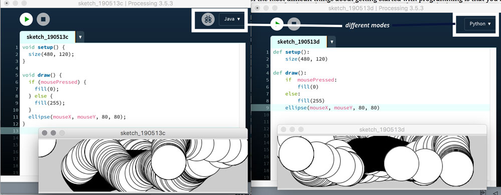
For the group assignment I was curious what the python mode means in Processing. So I looked at both Getting Started tutorials from Processing they give the same examples for Python mode which makes it easy to compare. In the first example, which draws a simple circle, you already see the difference in syntax. Python doesn’t need the semicolon at the end.
Normal Java mode:
ellipse(50, 50, 80, 80);

Python mode:
ellipse(50, 50, 80, 80)
The next example shows how to make the circle a little bit more interactive by adding a mouse click. While clicking it will change color. Again the difference between the Python mode and the normal mode is the way it’s written.
- Python uses on colon ‘:’ in stead of the curly brackets ‘{ }’ as they are normally used.
- Python uses ‘def’ in stead of ‘void’
 Different modes in Processing
To get a better understanding of the code and get more familiar how I could change it myself. I adjusted the sample code with the circles.
def setup():
    size(800, 600)

def draw():
    if  mousePressed:
        fill(255, 200, 200)
    else:
        fill(127, 0, 0)
    ellipse(mouseX, mouseY, 80, 80)
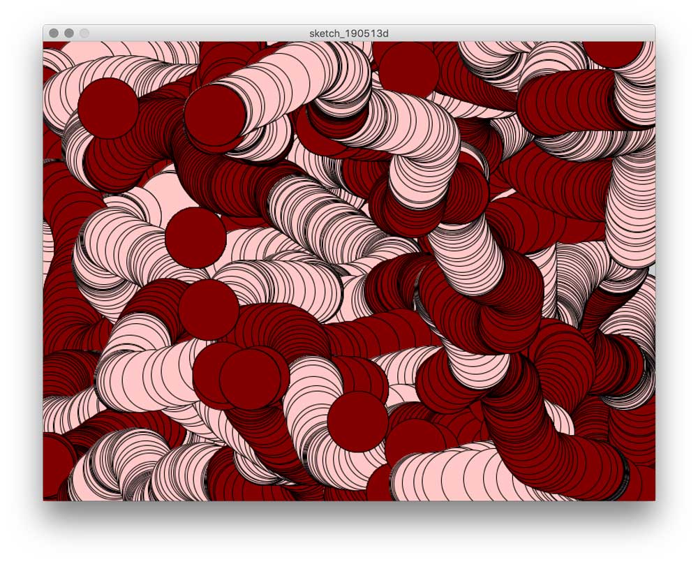
I changed the size of the window by changing the numbers in the setup behind size(800, 600). I changed the colors of the circle. In stead of black and white, I made it dark and light red. Dark red when the mouse is just moving, I changed the fill of the circle to fill(127, 0, 0) and the circle turn into light red when the mouse is pressed, with a fill of fill(255, 200, 200). Even though these are very small changes this helped me to get a better understanding of how the programing part works.
 Different colors and change is window size Processing example Python mode
Step 2: Setting up Serial Communication with my Tree Board and Processing.
After I finished these steps I wanted to see if I could setup Serial Communication using processing and my Tree board. In the Networking and Communications week I used this board to setup my serial network.
Testing if the Serial Communication still works.
My first step was to test if my tree board was still working with the serial communication. This was an easy quick test. My tree board still works and sends out 1, 2, 3, 4.
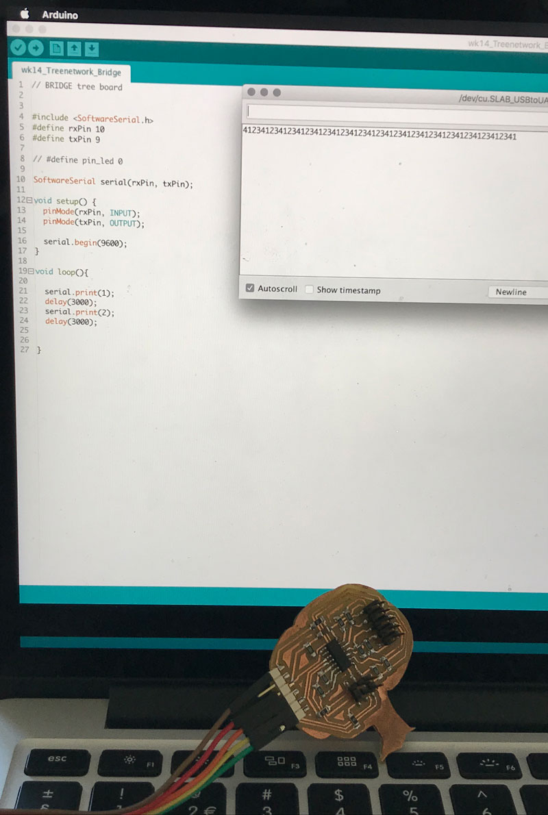 Serial communication tree board
Connecting my tree board with Processing
My next step to find out how I could set up serial communication was to see if I could connect the tree board, which sends out 1, 2, 3, 4, to an example serial code in Processing. To find these examples just go to File > Examples. This gives an pop-up with a folder structure. In the folder libraries you’ll find a Serial Library you can use for Processing. I first used the SimpleRead library.
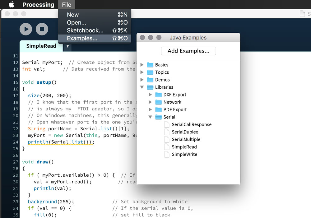 Example codes in Processing
To find out the port name of my serial port I had to figure out which number in the list is my serial port. Joey mentioned I could add println(Serial.list()); to my code to find out which port is my serial port. As you can see in the screen shot me it’s the second, as the first is bluetooth, this means I have to set the Serial.list to [1].
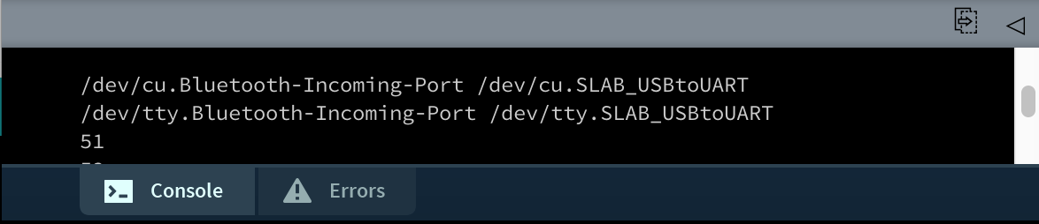 Setting the right serial port
  String portName = Serial.list()[1];
  myPort = new Serial(this, portName, 9600);
  println(Serial.list());
Reading the serial communication
After the setup and checking the right port. The program checks, reads, if there’s data coming from the serial port. It read the data and stores it in val, which is a integer defined on top of the program. In this part I also added a print line. This time I added println(val); to double check what my code is receiving
void draw()
{
 //It read the data and stores it in val.
  if ( myPort.available() > 0) {
    val = myPort.read();
    println(val);
  }
I connected the tree board and run the code. It gave me these results.
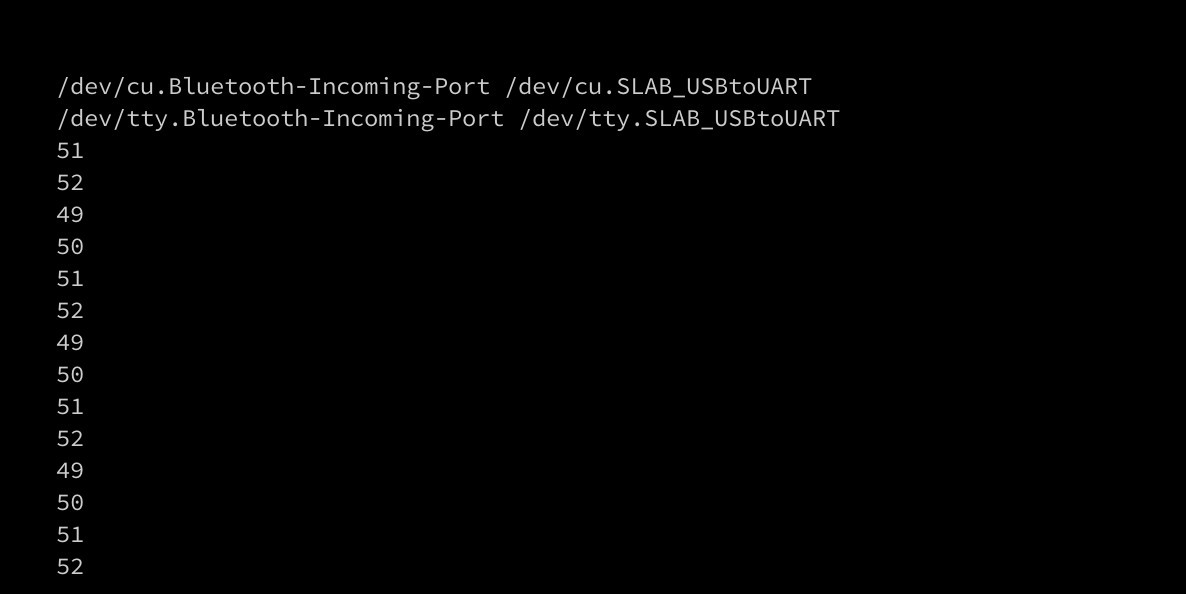 Serial communication between tree board and Processing
As you can see it gives the numbers: 49, 50, 51, 52, which is something else than the 1, 2, 3, 4 my tree board is sending. I remember the ASCII-table I used in the embedded programming week to switch case in Neils example code. I looked at it and I saw that the numbers it receives. 49-to-52 corresponds with the characters it sends 1-to-4.
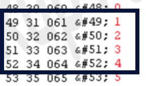 Ascii table: numbers 1 to 4
An small interface based on serial communication
To create a first start with a visual representation of the communication between my board and processing. I edited the given code in a very simple way.
 //This changes color based on the data it receives from the serial communication.
  if (val == 0) {              // If the serial value is 0,
    fill(0);                   // set fill to black
  }

  if (val == 49) {              // If the serial value is 49,
  fill(255, 200, 200);          // set fill to pink
  }

  else if (val == 50) {          // If the serial value is 50,
  fill(0, 200, 200);             // set fill to turquoise
  }

  else if (val == 51) {          // If the serial value is 51,
  fill(127, 0, 0);               // set fill to red
  }

  else if (val == 52) {          // If the serial value is 52,
  fill(0, 200, 0);               // set fill to green
  }

 else {                       // If the serial value is not 0 or 49 to 52,
 fill(204);                 // set fill to light gray
  }

//this creates a rectangle which switches color
  rect(50, 50, 100, 100);
}
I created a different fill for the rectangle for each number that is sent through serial communication. So the rectangle changes color based on the serial number that is sent through the FTDI-cable.
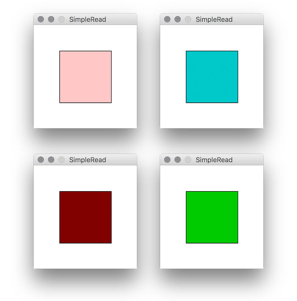 Simple Read: Serial communication with Processing and Tree Board
Step 3: Setting up Serial Communication with my Neopixel board.
The link with my final project for this week is that I want to be able to sent different modes to my Neopixel board. My idea is to first make a small test this week and see if I can rewrite the code from the networking and communication week in such a way that I could create four different modes.
I used the same code but cleaned it up a bit and added more of my own comments. The part that I edited is the colorWipe linked with the Serial Communication. For this test I made it as easy as possible, so I sent a 1, 2, 3, 4. And the Neopixel changes color based on the number sent. The next step is to link this with a Processing code sending 1-to-4.
//Based on the Neopixel Strandtest
//Edited by Micky van Zeijl - 13 May 2019

void loop() {
  //set the integer to the serial communication
  incomingByte = serial.read();

  //if serial communication sends a 1 it will turn the led to green
  if (incomingByte == '1') {
    colorWipe(strip.Color(255, 0, 0), 50);
    delay (2000);
    colorWipe(strip.Color(0, 0, 0), 0);
    delay (2000);
  }
  //if serial communication sends a 2 it will turn red
  else if (incomingByte == '2') {
    colorWipe(strip.Color(0, 255, 0), 50);
    delay (2000);
    colorWipe(strip.Color(0, 0, 0), 0); // off
    delay (2000);
  }
  //if serial communication sends a 3 it will turns blue
  else if (incomingByte == '3') {
    colorWipe(strip.Color(0, 0, 255), 50);
    delay (2000);
    colorWipe(strip.Color(0, 0, 0), 0); // off
    delay (2000);
  }
    //if serial communication sends a 4 it will turns to white
  else if (incomingByte == '4') {
    colorWipe(strip.Color(255, 255, 255), 50);
    delay (2000);
    colorWipe(strip.Color(0, 0, 0), 0); // off
    delay (2000);
  }
}

//colorWipe is a helper function. It's defined liked this in the strandtest example. -----
//For each pixel in the strip it sets the pixel's color (inRAM), it updates the strip to match with the colors with .show()
//It pauses for a moment with delay(wait)
  void colorWipe(uint32_t color, int wait) {
  for (int i = 0; i < strip.numPixels(); i++) {
    strip.setPixelColor(i, color);
    strip.show();
    delay(wait);
  }
}
Step 4: Writing a Serial Write program with Processing
My next small step is the write a Serial Write program with Processing because in the end I want to sent the 1-to-4 not with my tree board but with my interface that I made with Processing. So my first start again is using the example code of Processing.
void draw() {
  background(255);
  if (mouseOverRect() == true) {
    fill(204);
    myPort.write('1');
    println('1');
}
  else {
    fill(0);
    myPort.write('3');
    println('3');
}
I changed the ‘H’ to ‘1’ and the ‘L’ to ‘3’. This way I can connect it to my Neopixel serial interface as this one response to 1-to-4.
- Mouse on square: square turns to grey, it sends a ‘1’ over serial, which means the Neopixel board should turn it’s light to green, and it writes a ‘1’ to double check with the monitor.
- Mouse away from square: square turns or stays black, it sends a ‘3’ over serial, this means the Neopixel board turns it light to blue, and it writes a ‘3’ to double check with the monitor.
![]() Neopixel board connected to processing interface with serial communication
Neopixel board connected to processing interface with serial communication
To troubleshoot what is going on I reconnected the Neopixel board again to the Arduino code and Serial Monitor.
- My first step troubleshooting was repeating what I did be for and being sure it works. So like I did in my previous step I sent by hand a ‘1’ and a ‘3’ to the board and this time it worked like it should.
- The second step for troubleshooting was to recreate what Processing is doing with the serial communication. And I realized that I saw with the println() in the console of Processing that it sends the number really fast after each other. So I did the same in the Arduino IDE and send a lot of ‘1’ straight after each other before I would send a ‘3’. I had the same result as I had with Processing.
- To double test my idea I added a delay(1000), to my code and this worked. So I now know that this way the serial communication sends the numbers too fast for my Neopixel board to respond.
void draw() {
  background(255);
  if (mouseOverRect() == true) {  // If mouse is over square,
    fill(204);                    // change color and
    myPort.write('1');              // send an 1 to indicate mouse is over square
    println('1');
    delay(1000);
}
  else {                        // If mouse is not over square,
    fill(0);                      // change color and
    myPort.write('3');              // send an 3 otherwise
    println('3');
    delay(1000);
}
  rect(50, 50, 100, 100);         // Draw a square
}
![]() Troubleshooting Neopixel board and serial communication
Troubleshooting Neopixel board and serial communication
Step 5: Re-writing a Serial Write program with Processing
So my next step is to re-write the given example and to make sure that the serial communication only sends something when I want. The interface I want to make for this weeks works with a mouse click. So my first step is to make a mouse click in stead of a roll over.
Change MouseOver to Mousepressed
So My first thought was that I could just change the function (mousOVerRect () == true) from the previous step to a (mousePRessed == true) as you can see in the edited code below. I also change the else function where it now sends a ‘0’ in stead of a ‘3’ so the light should go off when it’s not pressed.
 if (mousePressed == true) {  // If mouse is over square,
    fill(204);                    // change color and
    myPort.write('1');              // send an 1 to indicate mouse is over square
    println('1');
    //delay(1000);
}
  else {                        // If mouse is not over square,
    fill(0);                      // change color and
    myPort.write('0');              // send an 0 otherwise
    println('0');
    //delay(1000);
This worked, however once I pressed on the square it also worked were ever I clicked and it kept on looping again. So timing wise I should fix some parts.
Changing the timing of the loop
While I was researching about buttons and interactivity in Processing I came across Event Flow, which they describe as:
“programs written with draw() display frames to the screen sixty frames each second. The frameRate() function is used to set a limit on the number of frames that will display each second, and the noLoop() function can be used to stop draw() from looping. The additional functions loop() and redraw() provide more options when used in combination with the mouse and keyboard event functions. If a program has been paused with noLoop(), running loop() resumes its action. Because the event functions are the only elements that continue to run when a program is paused with noLoop(), the loop() function can be used within these events to continue running the code in draw(). The following example runs the draw() function for about two seconds each time a mouse button is pressed and then pauses the program after that time has elapsed.”
noLoop();

void mousePressed() {
  redraw(); // Run the code in draw one time
}
This is what I need for the timing of my button. So I added some extra parts to my serial write program. I added the noLoop(); at the end of my void setup(), and I added the void mouPresse() with a redraw(); on the bottom of my code. I tested it and it worked a lot better. As you can see in the video.
Testing event flow with Neopixel board and Processing
Step 6: Designing the interface with Processing
The next step is to make a little bit more complex interface, although I still want to keep it really simple for this week. My goals is to understand each step.
changing the shapes
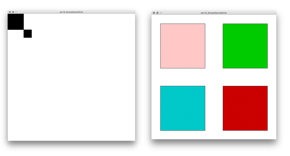
The first step was easy I just change the size of the window to a square of 800 pixels in stead of 200. And I added an extra square. The first to numbers are for the positioning of the squares
size(800, 800);
rect(100, 100, 50, 50);
rect(0, 0, 100, 100);
}
//other version:
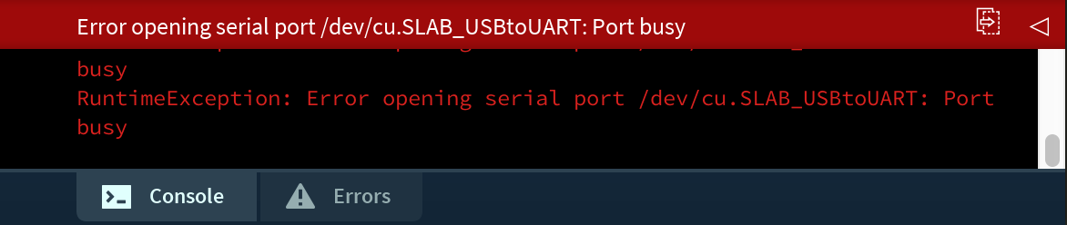
size(700, 700);
fill(0, 200, 200); //turquoise
rect(50, 400, 250, 250);
fill(255, 200, 200); //pink
rect(50, 50, 250, 250);
fill(200, 0, 0); //red
rect(400, 400, 250, 250);
fill(0, 200, 0); //green
rect(400, 50, 250, 250);
 Testing and experimenting with square sizes
making it interactive
The four squares are nice but right now they’re not buttons. So the next step was to make a small interface from the squares I made. However I was a bit lost how I could do this. So I looked for some examples online. They had a nice example at their own website.
I need something that registers the position of the square and the mouse for the Mousepressed and found this part in the example code:
boolean overRect(int x, int y, int width, int height)  {
  if (mouseX >= x && mouseX <= x+width &&
      mouseY >= y && mouseY <= y+height) {
    return true;
  } else {
    return false;
  }
}
This part uses the x and y position and the width and height of the square and links it to the position of the mouse. This way the click of the mouse is linked to the position it’s at. To test this I added the quick and dirty static values of each square.
  if (overRect(50,400,250,250)) {
     myPort.write('1');
     println('1');
  }
  else if (overRect(50,50,250,250)) {
     myPort.write('2');
     println('2');
  }

  else if (overRect(400, 400, 250, 250)) {
    myPort.write('3');
    println('3');
  }

  else if (overRect(400, 50, 250, 250)) {
     myPort.write('4');
     println('4');
  }
When I press each square I get the right numbers in the console of Processing.
![]() First version working of Neopixel interface
First version working of Neopixel interface
This should mean I could just add my board to the serial port and it should work straight away with my Neopixel board. So I checked if this was correct, and it was!
My interface
- the green square turns the light green
- the red square turns the light red
- the blue square turns the light blue
- the white square turns the light white
Interface working together with my Neopixel board
What I did wrong – and how I solved it
Serial port busy
In the beginning when I was testing the Serial Communication, I was using Arduino IDE and the Processing IDE for serial at the same time and got an error message. First in the Arduino IDE which said that the port was not available.
 Error message: Port busy Arduino IDE
Later on I got the same message while using Processing. My lesson learned is to make sure to close the port in the other program when you want to test and/or work with one of the IDE’s
 Error Message: Port busy Processing
Wiring of FTDI-USB
When I wire up my Neopixel board with my computer I always use an USB-FTDI connector. But every time I get confused with the wiring. Till I realized the one of my USB-FTDI is the other way around than my Tree board. So for my tree board I can use the right order. For the USB-FTDI I have to swab the RX and TX wires around.
Serial communication too fast
I was a bit frustrated that the first attempt of connecting my Neopixel board with my Processing code it didn’t work the way I thought. While in the end it actually did but the loop sent out the serial communication way to fast for my board to process it straight away. As mentioned above I added the noLoop(); and redraw(); to my code and this worked. But I think this isn’t a final total fix. What I would look at if I had more time is the Neopixel code. I think it also stores the number sent with serial and it has a delay. I think these both also interfere with the direct interaction of the interface.
What I learned
How to take it step-by-step
My goal for this week is to really understand each step of the programming. To make sure I really did, I took it step-by-step this week. For me it was more important to understand each small steps and to get a little bit further each time. Normally I don’t have the patience and I work a lot more with sample codes to make sure it looks nice or works the way I want it to.
What made me proud!
Normally I focus a bit more on how it looks and feels but for this week I didn’t have much time for fine-tuning. In addition, my main goal with the programming assignments is to understand each step. So even though I’m not specifically proud at the end result. I’m really proud on my process in understanding each part a little bit better and the small steps I took this week.
Credits and references
It was fun to have th Sorbonne Fab Lab students around for the group assignment. And Joey helped me a bit with the serial println to get more information for debugging. Most of my code is based on the tutorials and examples provided by Processing.