9. Embedded programming
| This weeks design | |
|---|---|
| fadelight | ino |
| threshold | ino |
Group assignment
For this weeks group assignment we compared different micro controllers. Each student was focused on a different type of processor. I was intrigues with the 555 Mad scientist processor. This is a self assembly kit to make your own oversizes micro controller. It is a oversizes replica of the the in 1972 developed ne555. It is a analog circuit which serves as a timer. The standard package functions on 25 transistors, 2 diods and 15 resistors and has 8 pins.
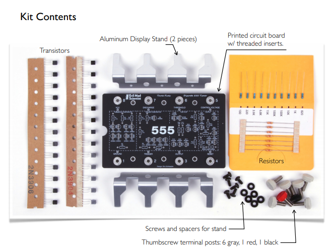
Link for download mad scientist datasheet
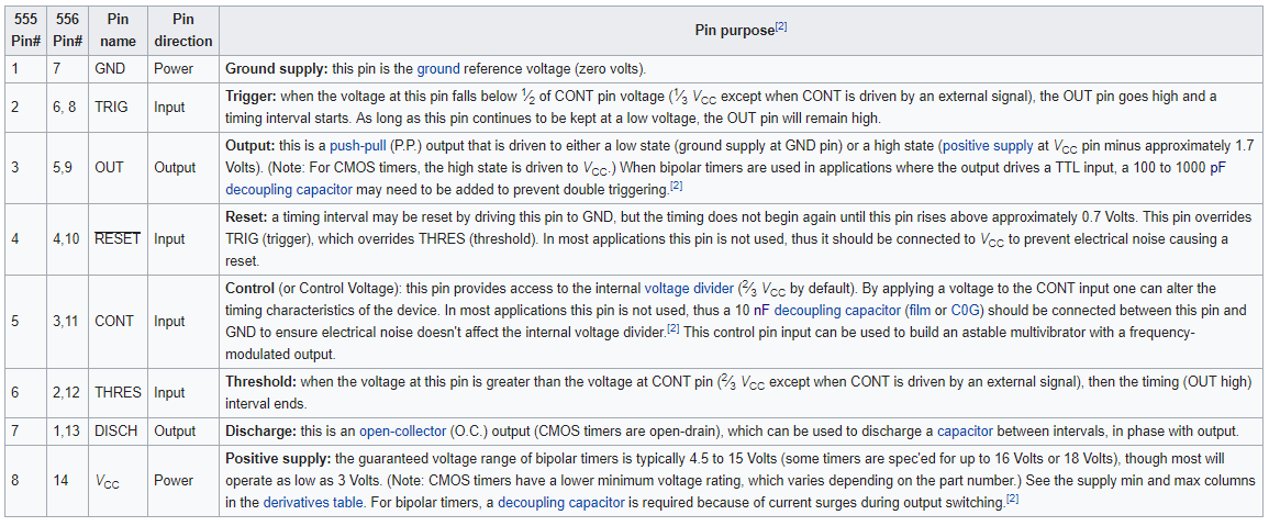 Overview of the pins and their function (source wikipedia)
The 555 has been used in many applications thanks to its high stability and is used for accurate time delays and oscillation. It is the first circuit that could use Pulse width modulation to create more variations.
-
We compared different specification of the processor using a datasheet. I compared the outcome to see difference in controllers.
-
Voltage: The one jumping out is the se 555. While the others operate with a voltage between 2.5v and 5.5v this old processor can handle up to 18 volt.
-
Chip architecture esp8266: Tensilica L106 32-bit RISC processor es555: Precision Timer 8-PDIP -55 to 125
Raspberry PI Zero: BCM2835 SoC Makey Makey Classic v1.2:PIC18 F25k50 -
(clock)speed The raspberry won this contest with a clockspeed of 1 Ghz
-
Memory The SE555 is the strange duck and have no memory.
-
Pins (type and amount) the Makey makey have lots of pins. Much more then the other devices. It has 28 i/o pins
- other special features While the se555 is specialized in timing the esp8266 comes with a variety of special features mostly on communication.
- How do you connect the device While the esp8266 comes with a few ways to connect the raspberry pi have newer more efficient way of connecting.
- programming environment The different devices comes with different software. The se555 is still analog and you program it analog.
- programming language Other programming languages accepted for the different devices. No particular program language. The raspberry pi recommended using python but enables other languages
- how do you get code on the device The raspberry pi works with a sd card to get the code on. Other devices use the serial communication pins. The SE555 can’t be digital programmed.
From the different devices i would crown the raspberri pi zero as the winner. It was not a fair competition since this device is not a controller but a processor. It is a mini computer on it self. A special mention of the se555, which is one of the first of it kind and still does not disappoint. Still this device is used because of its reliability and good timing qualities.
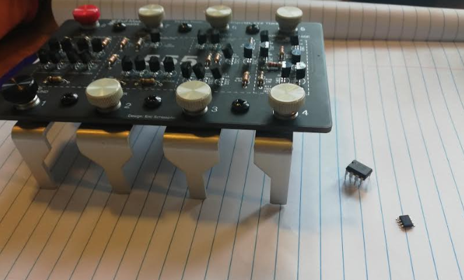 The family 555
Datasheet AtTiny44A
The next fun exersize was reading a datasheet. The board i made during the fabacademy has a attiny44a processor. http://academy.cba.mit.edu/classes/embedded_programming/doc8183.pdf I found it extremely difficult to read a datasheet. Its full of terms and functions i don’t grasp yet. I can see the importance of knowing the specifics of the processor. this knowledge enable u to use the full potencial of this funny little device. And also to understand the functions of the different pins. I started writing the chapte a few times and started over. In the end i decided to make a summary using the pictures of a few improtant chart. In a visual way i can understand the aspect of the datasheet much clearer.
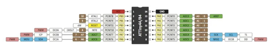
When starting embedded programming it is essential to know which pins to use for which purpose. All the different pins have other functions. Without appointing a function to a specific pin the command won’t work so it is a good practice to learn about the different functions.
Btw Neil.. Its not fun at all..
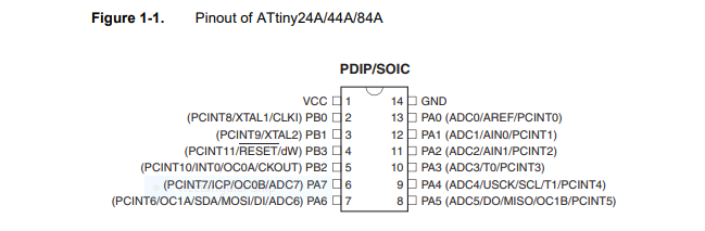
The Attiny44 have 14 different pins. In this image you see the function of the different pins. Some pins have a very specific function like Vcc and gnd. Other pins can be use for multiple purposes. It is important to know which pin can be used for which purpose. In general you often go back looking at the pin functions. The Vcc and Gnd use both one pin. The other pin are devided in port A and port B.
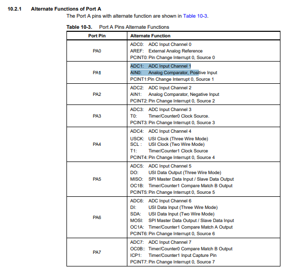
PA stand for port A. This is a 8 bit bi-rectional gate. Pa0 to pa7 can be used for analog input and output. Further it gives a handy overview for what function to use which pin. PA pin have analog inputs for adc (analog digital converter),analog comparator,timer and spi (Serial Peripheral Interface) Pin pa5 and pa6 have miso and mosi which are used to program the board using a isp header.
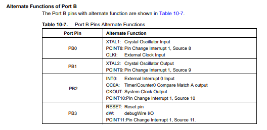
PB stands for port B. this is a 4 bit bi-directional port. pin pb3 is the reset port. PB0 and PB1 are used to place a external resonator for better timing results.
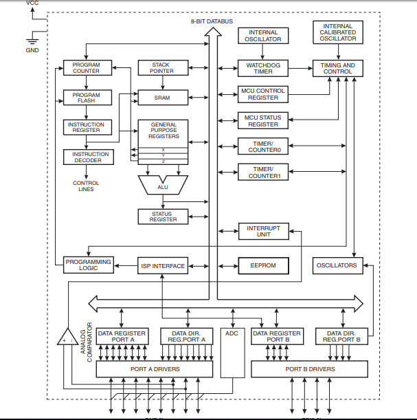
This image gives a good overview of the infrastructure of the micro controller. It comes with 32 registers connected to the Arithmetic Logic Unit. I found this page useful in explaining the purpose of a register. It compare it to a tape recorder which can have different function depending on the buttons you press. The buttons in a register are binary and are off (0) or on (1) This enables you to complex information through the registers. The register are connected to the ALU Which do the calculations and operations of the registers.
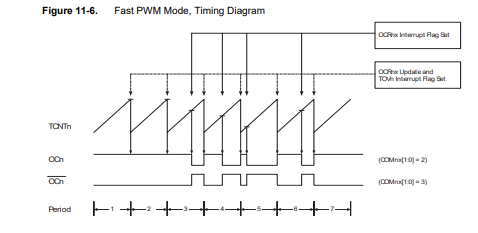
Pulse width modulation enable you to increase or decrease the average power supply by a electrical signal. You can determine the length of the input with high or low voltage. To decrease voltage you turn low on for a long period and high for a short period. This method enable you to combine 255 different settings. PWM is often used to determine brightness of a led or volume on a stereo. Pins PA 5,6,7 and PB2 can be used for PWM.
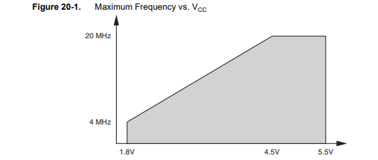
Explains the relationship between the amount of volt and the frequency. The higher the voltage the higher the frequency. The speed in which the frequency travels. The max amount of frequency with the attiny 44 is 20MHz and this max is reached with a voltage input of 4.5
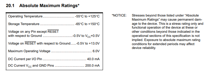
Here is a description of the maximum rating this device can handle. It is good to know what the max amount of voltage is the device can handle and the amount of current you can apply to the pins.
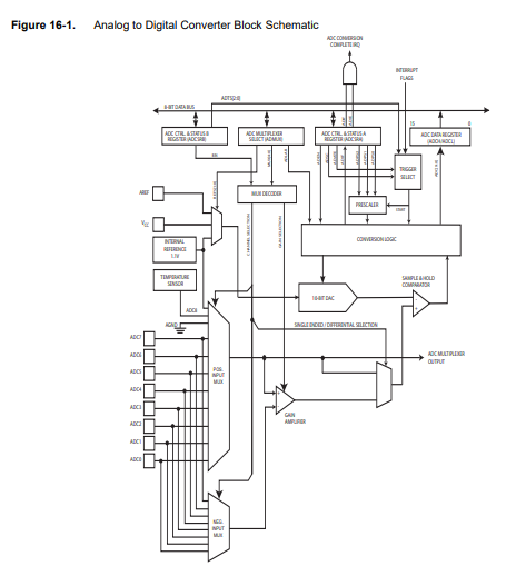
The adc (analog to digital converter) convert analog input voltage to a 10 bit digital value using the gnd as minimum value and the maximum value for the voltage applied. There are 8 pins that have this adc function.the 10 bit is presented in the ADC data registers. It has its own interrupt function which gives priority to the function.
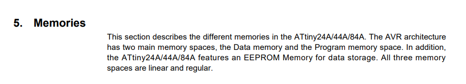
I wanted to add the memory also to the list for better understanding of the different types of memory used. The flash memory is used for transfering data between computer and device. It can be reprogrammed and erased. In the attiny 44 it can be erased minimal 10.000 times. Flash memory retains data even in absence of a power supply. sdram (Synchronous dynamic random-access memory) is capable of keeping two sets of memory addresses open simultaneously. It use the 32 registers and the 64 I/O registers and internal sdram 128/256/512 bytes for storage. This device contains 128/256/512 bytes of data EEPROM memory and has its own storage place. In my understanding has this similar function to the flash memory and can be erased and rewritten also. The difference is that flash memory is programmed and rewritten in large blocks. source
Program a board
There are many different environments you can use to program the board. You can use the terminal to write the commands or make use of opensource arduino IDE or several program on the market. My preference is a easy environment with a clear simple programming language. Coding is new for me and Arduino IDE seemed like the most logical environment to start. Also there is a big online community for this platform which is perfect to get information or feedback.
Avrdude is another tool to program your board. Our instructor gave us a demonstrating in how this interface is used. Mostly he focused on troubleshooting when device not working as expected. I would like to use the terminal at least as possible since i am a real trouble maker in the use of the terminal. I added a overview of the interface from his instructions.
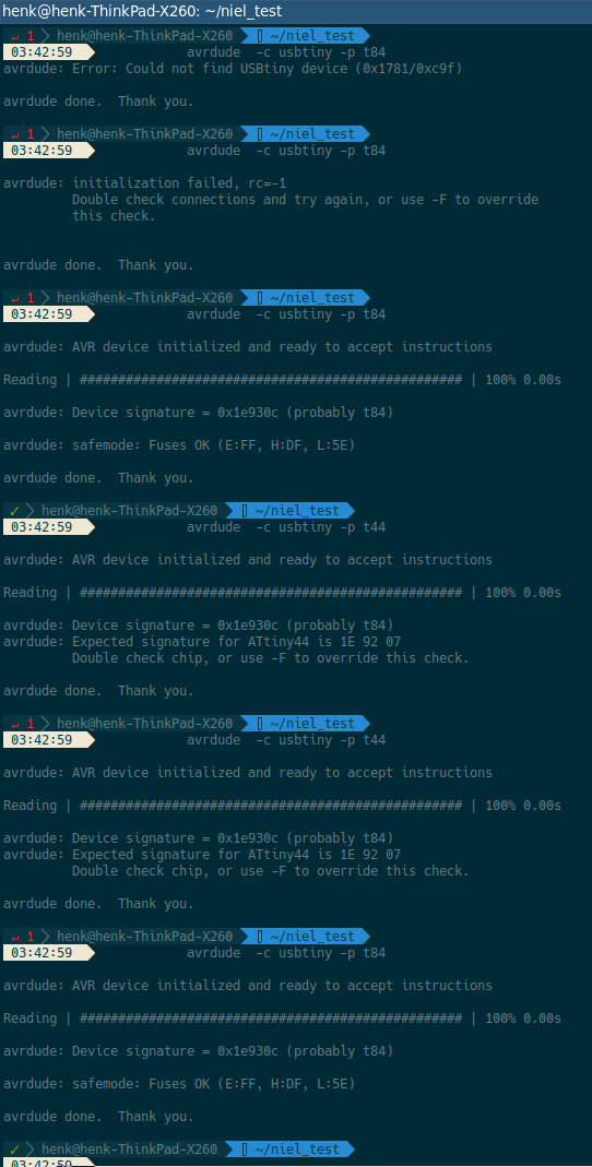
Overview connectivity issues AVR and board
Arduino IDE
The first step is to download the software. I downloaded the latest version of ide. website arduino
To be able to read the board we using we needed to add the board in the software. A link you have to copy and paste in the url setting. The url you add into file --> preferences -->additional Board managers
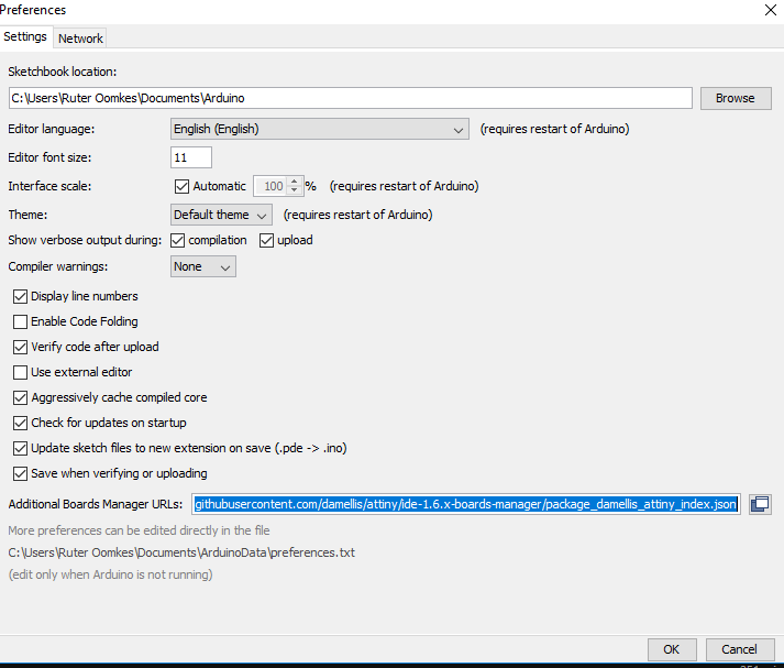
in the url you paste the addres to recognize the attiny
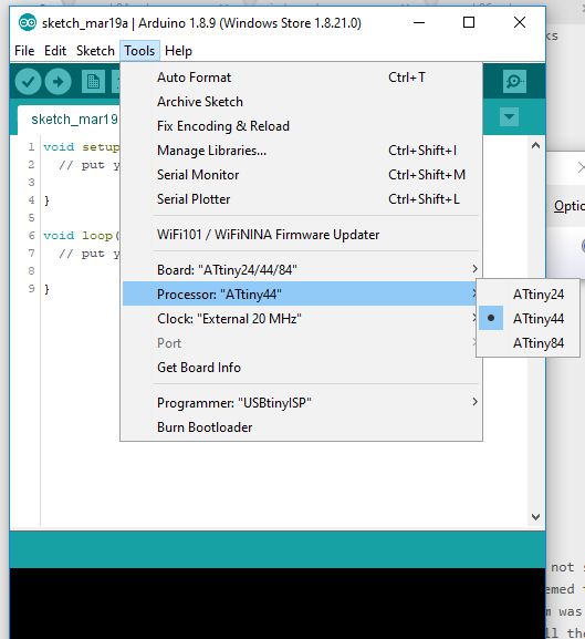
In the setting menu you add the correct board type, the processor type and the clock speed on 20 mhz. And the programmer you can set here as attinyISp. Which is the device we made to program the board.
When connecting my device to the arduino ide software the first step was a bootload. A boot loader enlarge the capabilities of a microcontroller and makes it a self programmable device. The boot loader can use in this instance spi to exchange data and has the capability to write the flash memory. The boot loader writes the high and low fuses values of the chip..Bootloaders allow code to be flashed to a microcontroller without specific programming hardware. Usefull site
another thing that was done was including the softwarSerial. This is a library which enable you to have serial communication with the board and arduino ide. With this library you can use other digital pins for communication. This had to be verified and uploaded to the board. When this was set we could start playing with the code.
At first i just tried a existing line of code to see if my board was responding. This was a code to use the button. I had a issue with the push button. The command did not seem to work. I checked with a voltmeter if the button was correct. seemed to work. I did not know where to search the issue. In the end the problem was the pin that controls the button from the microprocessor was not well soldered by me. I resoldered the pin and afterwards the button worked good.
playing with the code.
#include <SoftwareSerial.h> // import another program, a library, to communicate
#define rxPin 0 // this is simular to the int = setting, however this is linked to the library
#define txPin 1
SoftwareSerial serial(rxPin, txPin);
int pin_L_sensor = 2;
int value_L_sensor = 0;
void setup() {
  // put your setup code here, to run once:
  pinMode(rxPin, INPUT);
  pinMode(txPin, OUTPUT);
  pinMode(pin_L_sensor, INPUT);
  serial.begin(9600);
}
void loop() {
  // put your main code here, to run repeatedly:
  value_L_sensor = analogRead(pin_L_sensor);
  serial.print("the status of the button is: ");
  serial.println(value_L_sensor);
  delay(1000);
}
I have no experience in programming and to get used to the terminally, codes and interface i started watching a serie of tutorials about arduino IDE. I started with lesson 3 when it starts programming. I love these tutorials. There very informative and explained in normal language. This Really help me understanding the logic of programming. Arduino tutorials
In the tabel below i added the command i learned from this tutorial serie.
Arduino ide basics
| This weeks design | |
|---|---|
| // | Used for message to explain the code |
| / / | When using multiple lines of messages |
| ; | In this language this is used as a period. Without the code does not work. It is used to initialize the written code |
| Void setup | The function of the code |
| () | All code is in here. There is a lot of hidden code which is stored in there |
| Enclose further information about the setup. Will include in the existing code | |
| int | This is data type. With this you create a variable. In many cases you give a value to the variable. Later in the code you give meaning to the value given. |
| const int | With this declaration you make a constant of your variable. |
| variable | Often u define this after the data type (which are colored. Variables are changeable. Use clear descriptions |
| led = 13; | Here define the variable as 13, next time u use the word led it knows the number is 13 |
| -32.768 to +32.768 | The range of numbers you can use. When using more it continues at the max minus |
| int led =13: | int (declare led (variable) 13(value) ; initialize |
| Void setup | In the setup you initialize variables, pin modes, start using libraries, etc. The void setup only runs once. |
| output | information to board |
| input | read input |
| Void loop | A loop is the code that runs over and over again. You can set condition in when the loop stops. |
| Digital write | high of low voltage applied to a specified pin |
| Digital read | return information in 1 (high) and 0 (low) |
| analogWrite | A certain percentage voltage applied to a specified pin. Used with PWM |
| analoRead | This read the amount of voltage on a analog pin between 0 (0 volt) and 1023(max volt) |
| high | voltage high or 1 |
| low | voltage low or 0 |
| (delay) | Pauses the program for the amount of time you set. Measured in mili seconds |
| Serial.Println | Prints the data to the serial monitor. For every reieved data it starts on a new line. |
| Serial.begin | This will establish a line connection (standard 9600 bautrate |
| pinMode(pushbutton, input); | Pinmode decide which pin. This case the declared pushbutton. The input result in reading the voltage input |
| Serialprintln(sennsorvalue); | This will print the information from the variable, in this case the sensor value |
|| |
the or sign |
| if | Data type used when certain condition are met then it results in a action which you have to declare |
| variable = - variable | The minus sign is -1. When a max is reach it does -1 * variable |
| == | Comparison operator: the one equal sign is alreeady used to declare variables |
In arduino software you don’t use space with variables. Further it is common to start the second word with a capital letter pinMode is a good example. When using multiple words only use the capital letter in the second word. When a command is taken from the library you don’t start with a capital letter and there is a dot to indicate its taken from a library.
first coding
First code written with help of fellow student anne
Just to learn the logic of embedded program i used one of the examples but with own written code. i want to explain for every piece of code why you use the specific commands.
#include <SoftwareSerial.h>;
#define rxPin 0
#define txPin 1
This first code is to include the softwareSerial.h in the code. The define function is used to define the rxPin (recieving pin) and and txPin(transmitting pin). Since you retrieve this from a library you use the #define instead of the int.
SoftwareSerial serial(rxPin, txPin);
Here you define which pins are used to establish a serial communication.
int led =7;
int brightness = 0;
int fadeAmount = 1;
Int is a datatype to declare the variables. For example led = 7. Now you know that led is equal to seven. In the coming of your code you only have to name led and it knows its seven. It still does not give a meaning to the numbers.
void setup() {
  // put your setup code here, to run once:
pinMode (led, OUTPUT);
serial.begin(9600);
}
In the setup you set the function of the code. In this case the led is declared to the pin 7 and is declared as a output.
serial.begin(9600) is used to establish a connecting between the board and software. The dot in the middle shows this code comes from the library. You use 9600 baut as a default for communication.
void loop() {
  // put your main code here, to run repeatedly:

analogWrite (led, brightness);
brightness = brightness + fadeAmount;
if (brightness == 0 || brightness == 255){
  fadeAmount =-fadeAmount;

}
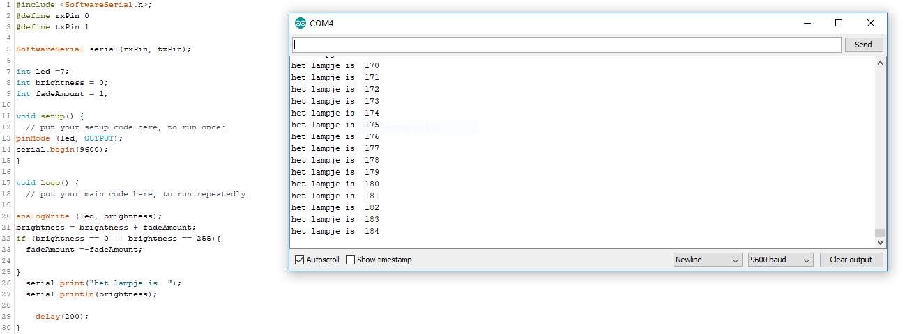
The void loop is where the action takes place. In a never ending cycle. AnologWrite u define the two variables led and brightness. AnologWrite enable to control the brightnes of the led in number from 0 to 255. Digital write would only enable you high/low output. In the next code you add two variables to see a change in brightness. The if command is used to set condition to the variable. In this case the max (255) and the lowest (0). So if this condition is met then fade amount =-Fade amount. the minus sign is -1. This way the fadeamoubnt automaticly goes back when reach the highest amount and vice versa.
serial.print("het lampje is  ");
  serial.println(brightness);
    delay(200);
The last code is again taken from the library since there is a dot in the code. This line of code enable you to see the data of the brightness of the led. With the first line you name the information coming in. In this case we only recieve one input but the moment code becomes more complex it is a good habit. The second println indicated what it wants to show. In this case the value of the brightness. The delay was set on 200 millisecond to be able to see the changes in the led.
When the first code was succesfully executed i wanted to add a extra feature in the code using the phototransistor. I wanted to archive that certain threshold results in the led turns on or off.
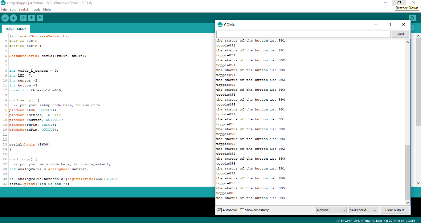
Data of the phototransistor coming in and a threshold of 915
#include <SoftwareSerial.h>;
#define rxPin 0
#define txPin 1

SoftwareSerial serial(rxPin, txPin);


int value_L_sensor = 0;
int LED =7;
int sensor =2;
int button =3;
const int threshold =915;
The first section is the same as in my first written code. In the declarations there are 3 new variables. The value_sensor is ment for readingg the data. The sensor is the phottransistor and lastly there is a constant variable with 915 as turning point. The numbers don’t mean much yet till described in setup.
void setup() {
  // put your setup code here, to run once:
pinMode (LED, OUTPUT);
pinMode (sensor, INPUT);
pinMode (button, OUTPUT);
pinMode(rxPin, INPUT);
pinMode(txPin, OUTPUT);

serial.begin (9600);
}
In the setup the sensor is declared as input. For reading the data that comes out the serial communication the rxpin and txpin have to be declared as well.
void loop() {
  // put your main code here, to run repeatedly:
int analogValue = analogRead(sensor);

if (analogValue>threshold){digitalWrite(LED,HIGH);
serial.print("led is aan ");
}
if(analogValue<threshold) {digitalWrite(LED,LOW);
serial.print("led is uit ");
}
First the analog value is set equal to analogRead which is the sensor. Analogwrite goes from 0 to 255. Now we use analog read which goes from 0 to 1023. The iff sign is ment for when the condition is met which is in the first code lower then the treshold which i put on 915. Digitalwrite decide here that the led is on when the analogvalue is higher then 915 The second if described the alternative when the number is lower the led will be off.
value_L_sensor = analogRead(sensor);
serial.print("the status of the button is: ");
serial.println(value_L_sensor);
delay(1000);

serial.print ("toppie");
serial.println(analogValue);

delay (1);
The last section of the code is to retrieve the data on the serial monitor. First we declare the the value_L_sensor is equal to the analog read(sensor) Now we can use serial print to name the data that comes in and serial.println to retrieve the data with a delay of 1000 milliseconds. The second print is from the previous code which i did not retrieve on the serial monitor.
What i learned and what went wrong.
this week i got a peak of the amazing world of programming a board. I am intrigued with the possibilities. From the tutorials i understood the logic of the code. In practice it is still confusing and daunting. It is never the less a topic i would love to know more of. I never realized before this week a blinking led could make so childish happy. Electronics i still find very difficult and reading the data sheet was pure horror for me. Most parts i did not understand. What did help me was to get a better insight of the different pins and there functions. At least able to find which pin is used when.