Casing
The shell of the machine, which holds the bearing system and the motor.
Machine Casing
There were two different attempts at creating the casing of the machine. The first one was done using the rods from the previous year’s machine, and the second one was done after purchasing new rods and so adjusting the pieces for the size of the machine we had chosen (60 x 90 cm). Therefore, two very different casings were made, the first testing out how the measurements had to be taken and the second with the final shape.
First test
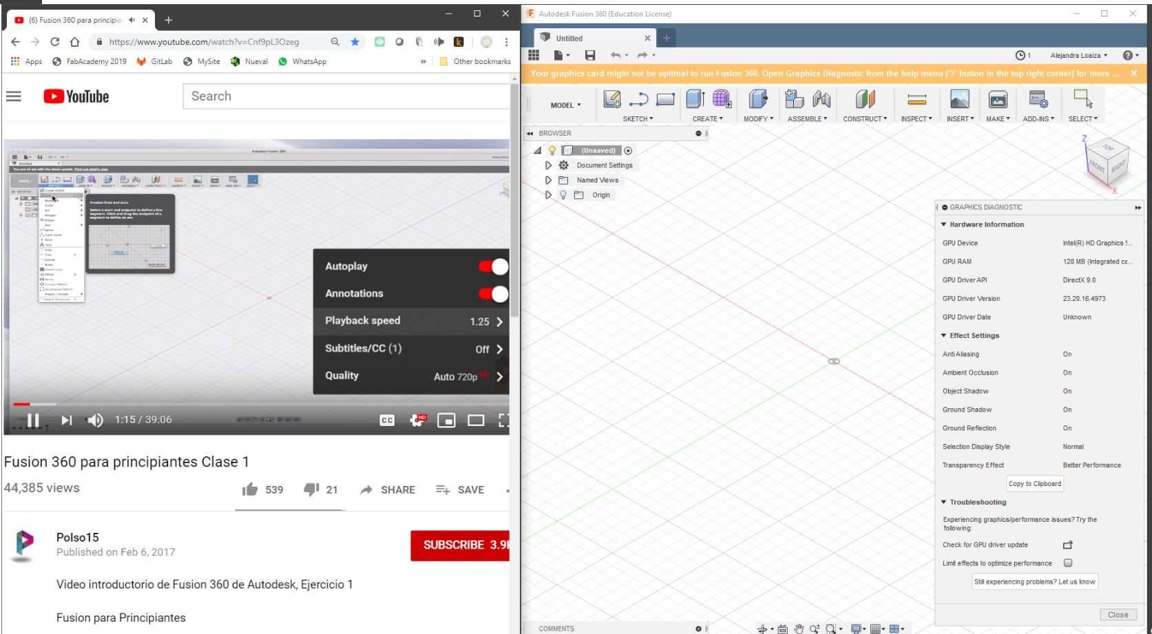
For the first test, I created the model in fusion 360 experimenting with parameters. At first I designed the machine for the size of the rods we had available (43 by 53 cm) and used these measurements to configure the pieces. However, after seeing the motor case designed by Jorge assembled with the bearing pieces designed by Danny, I realized that I had been designing wrong, as the proper way to create the case was using the distance between the rods (the vectors on which the machine would move).
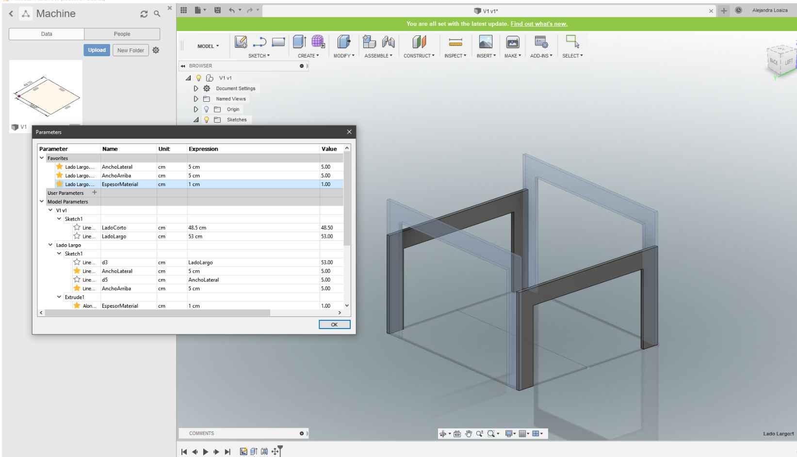
As I had done the design parametrically, modifying the 3D was no problem, and the pieces were soon made and ready to be cut.
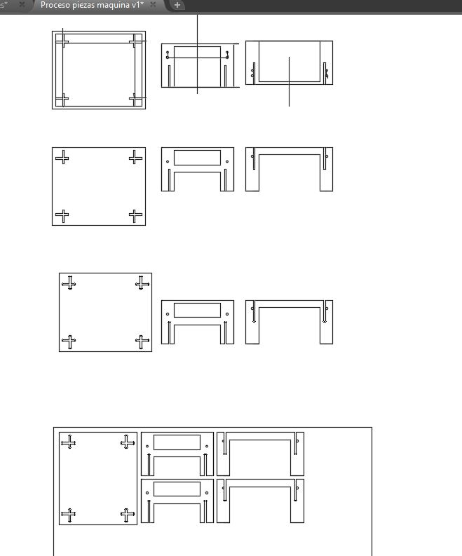
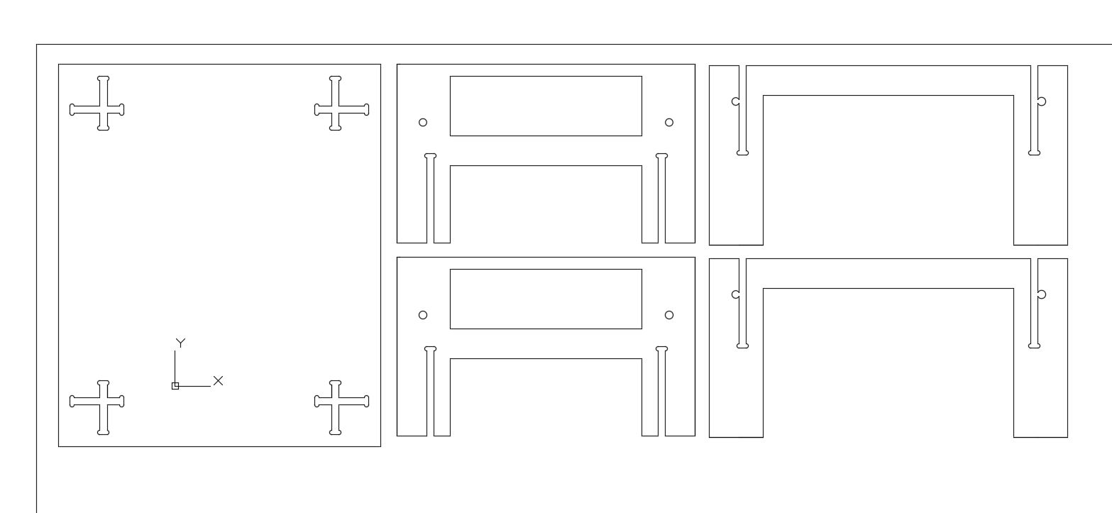
I exported the pieces into dxf and in AutoCAD I added the t-bones. As I was using a 6mm tool, I created the tbones with a 0.7 diameter.
As I had not used the CNC in a while, I had to re-learn how to create the code and send it to the machine. For this, I used ArtCAM, and after exporting the toolpath three different times (as I kept forgetting to add different settings), the g-code was finally ready and working properly.
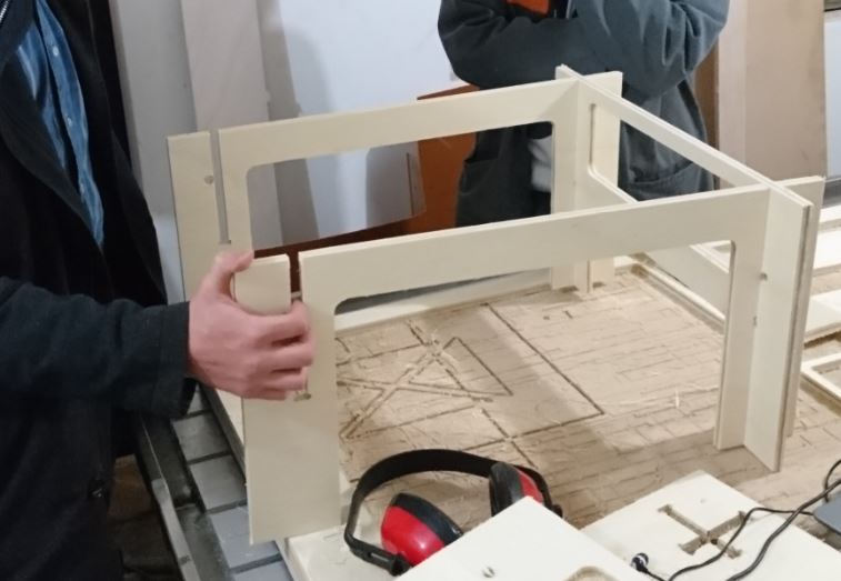
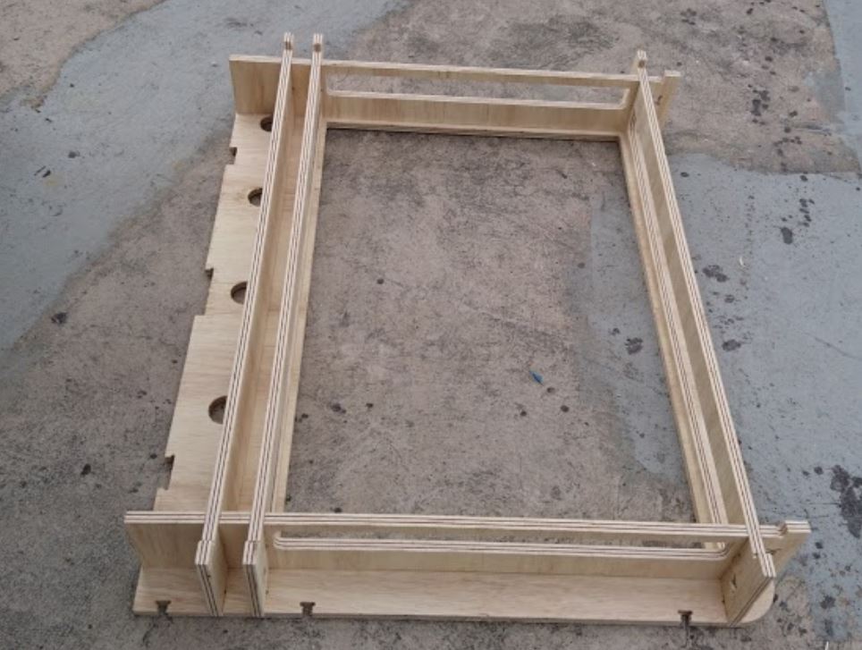
The pieces were milled, sanded and ready to be assembled, which was done without a problem as the press fit had been calculated properly (and also due to the simplicity of this initial design). The rods were placed along with the parts of the machine and so the whole assembly was tested mechanically, and it worked properly.
Second Test
Seeing as the first test worked properly, I proceeded to create the second test (or final casing) of the machine. We decided upon a size of 60 by 90 cm, seeing as this was close to the size of a A1 paper and we wanted the machine to be able to draw architectural plans and perspectives.
Also, we wanted the machine to be easily “fabable” in another lab, so the casing design was made using 15mm plywood and is easily cut in a CNC machine. We wanted the machine to stand on only one side, so as to leave the 3 other sides open to easily insert material and also so that there would be no visual obstacle when observing the movement of the machine.
In order to start creating the casing, there was one fundamental measurement that had to be taken: the distance between rods, in vertical and horizontal. The bearing system consists of 4 rods in a square shape, with parallel rods being at the same height. The distance between rods in this system is determined by many factors: the vertical, by the distance between axes in the motor that Jorge had done, and this combined with the distance between the bearing axis and the moving axis from the motor; the horizontal by the length of the screw of the stepper motor, and the distance of the joint from this screw and the bearing piece from the external rod.
The screws for the motor that we sent to be made were exactly 90cm and 60cm. The bearing pieces that we were going to use were the same ones as the ones we used for the test, and they gave us a distance for 3.4 from the joint to the edge of the rod. Therefore, the distances between rods in horizontal were 66.8 cm and 96.8 cm.
The distance in vertical, from center to center, was 3.75, as determined by Jorge’s design for the head of the machine and the fact that Danny’s bearing pieces did not deviate the axes vertically.
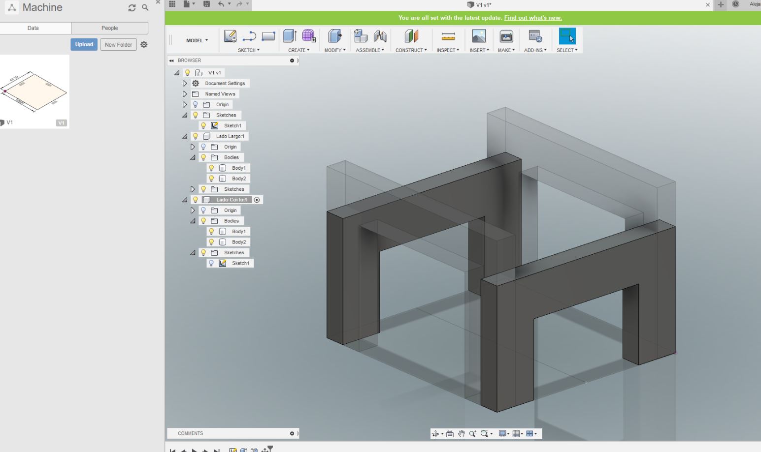
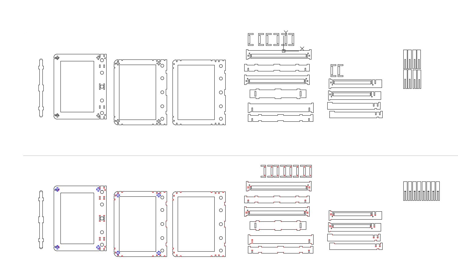
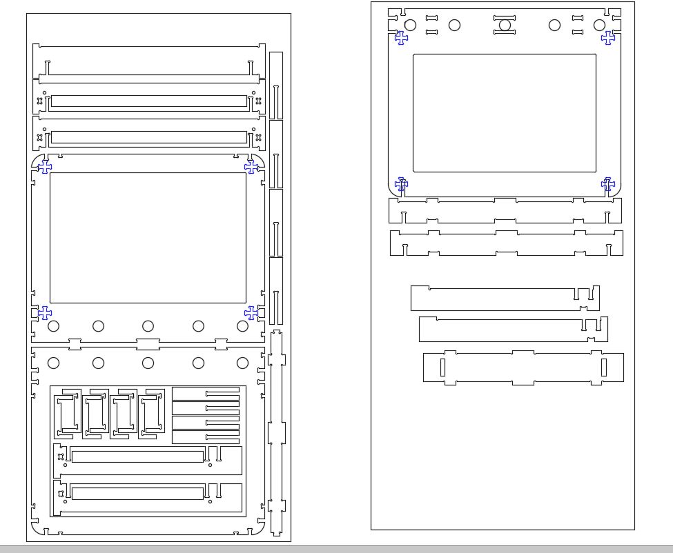
With these measurements I began the 3d modelling of the casing. I created first the holding pieces for the rods, making the rods join on the external part of the shape and creating a cut corresponding to the horizontal movement of the machine. These joined vertically in pressfit, creating the main bearing space for the machine.
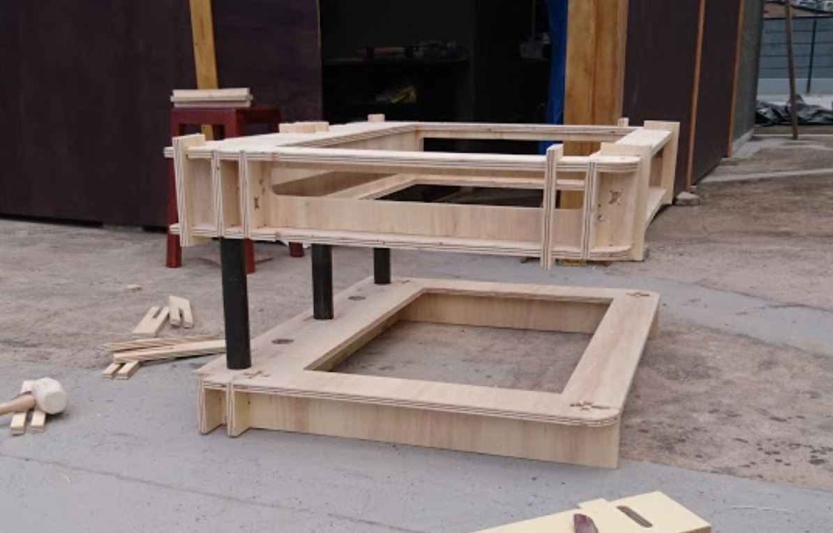
These pieces were then sandwiched by a top and bottom base, to make it sturdy and to be able to only support it on one side. As it is going to be supported by thicker rods, which were going to be pushing on the top part of the casing, I decided to secure the top and bottom parts together with small C-shaped pieces that kept the top and bottom secured.
As the steel tubes would only be placed on one side, there is going to be a lot of torsion, so the base was made 10cm thick with main plywood elements creating a sort of box where the tubes would be inserted, the box being the right size to hold the tubes very tightly.
The model was completely defined in Fusion 360, and then exported into SketchUp (a software I am more familiar with) in order to export the pieces as 2d shapes and create the milling file.
I had forgotten to greate the t-bones in the 3d model, so I added that to the pieces in AutoCAD.
Milling the Pieces
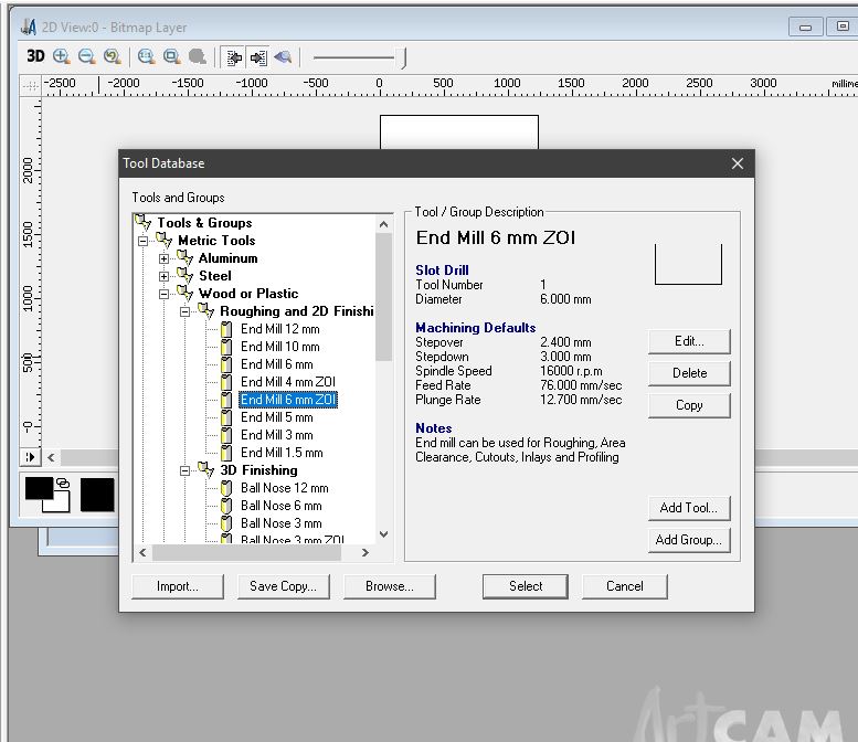
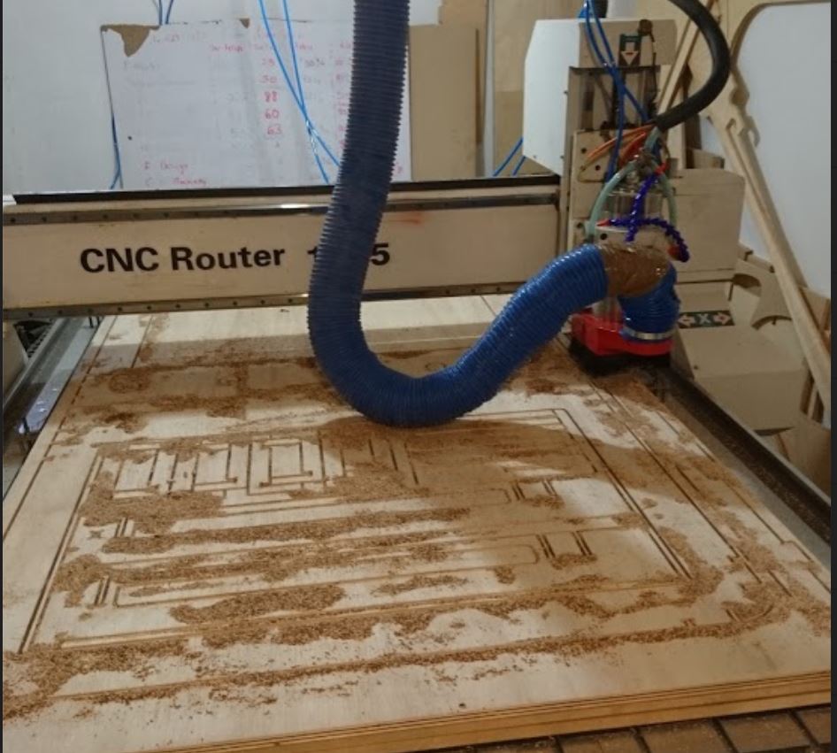
The g-code was created in ArtCAM with the following specifications:
End mill 6mm:
- Stepover 2400 mm
- Stepdown 3000 mm
- Spindle speed 16000 rpm
- Feed Rate 76000 mm/sec
- Plunge rate 12700 mm/sec
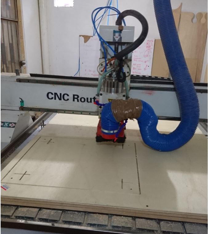
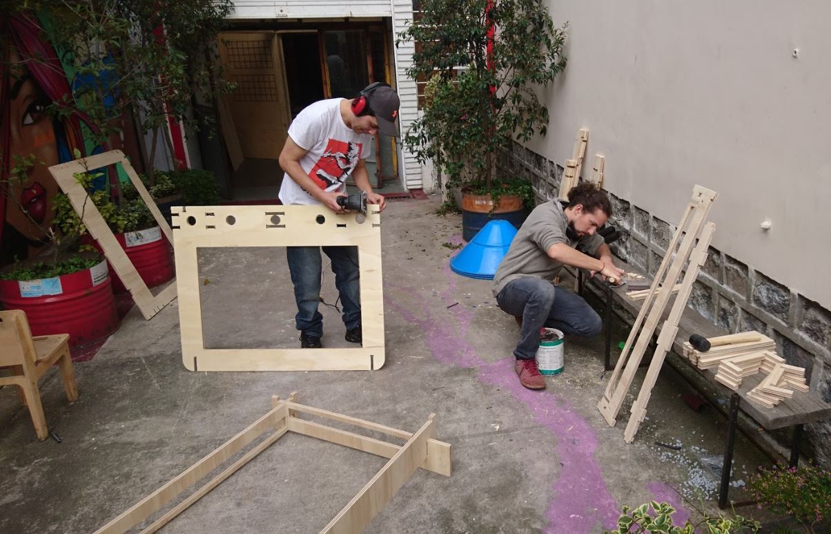
After the material was secured onto the CNC, the cutting went well without any problems. I created 4 bridges in the toolpath for each piece, 3 mm thick and 8mm long, which very successfully held the pieces together and allowed the milling to go smoothly.
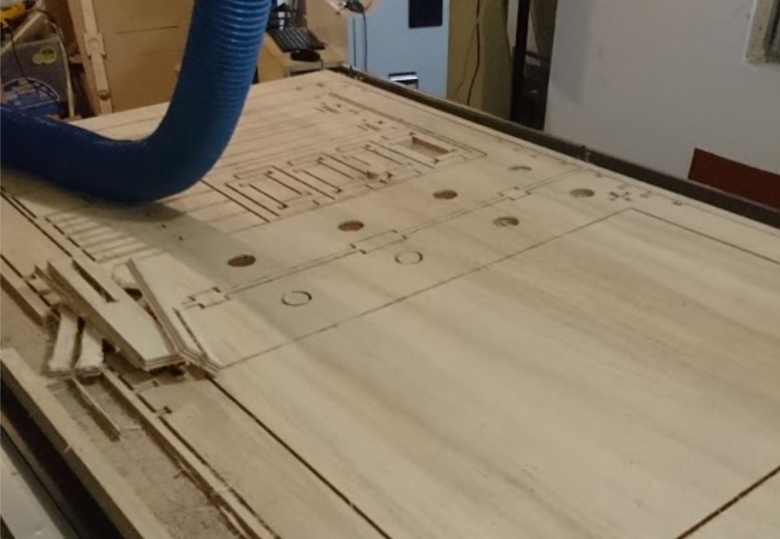
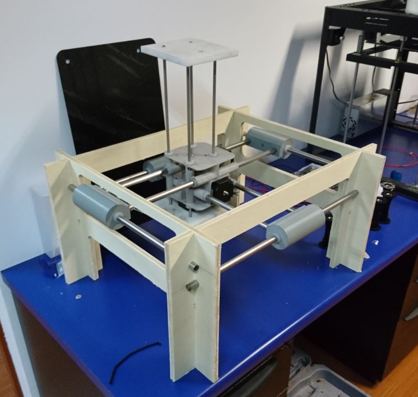
After everything was milled, the pieces were removed and then sanded. Sanding the pieces turned out to be a very long task, as there were many pieces, and the thickness of the material was irregular in some parts. The pieces required a lot of sanding because the wood wasn't of the best quality, and the end mill was a little old.
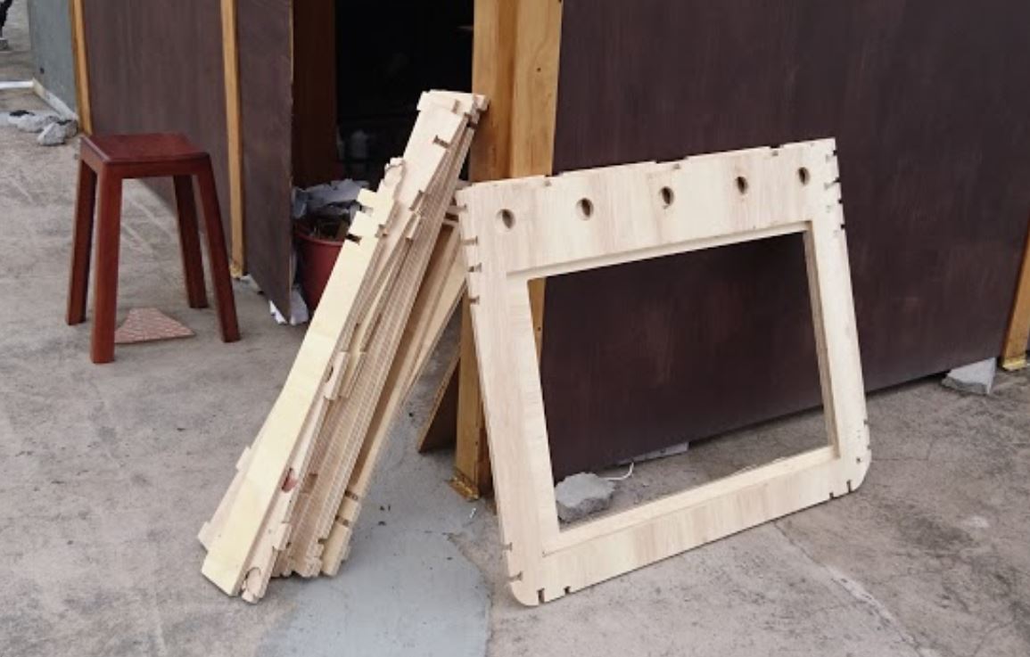
The pieces were assembled, and the last part that was joined were the tubes that held up the machine. These were able to hold up the machine despite the size and torsion generated, ad the machine was ready to be assembled with the motor.