5. Electronics production
This week is a start of a completely new topic to me. I have never thought I will understand the complexity of Electronics ! But here I am.. I managed to do my first in-circuit programmer. Let me tell you that it was very interesting!!
Below I will try to simplify this process to the complete beginners like myself :)
Machine Characterization
PCB Fabrication
For this assignment we were asked to produce and program a circuit programmer which we will use to program other things later. We had an option to choose from 3 available programmers:
- ISP (AVR)
- UPDI (AVR 0,1-series)
- JTAG (ARM)
I decided to choose the JTAG (ARM) hello.CMSIS-DAP.10.D11C
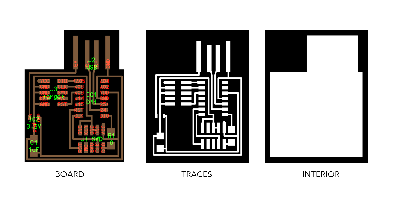
So I uploaded the png files I needed from here
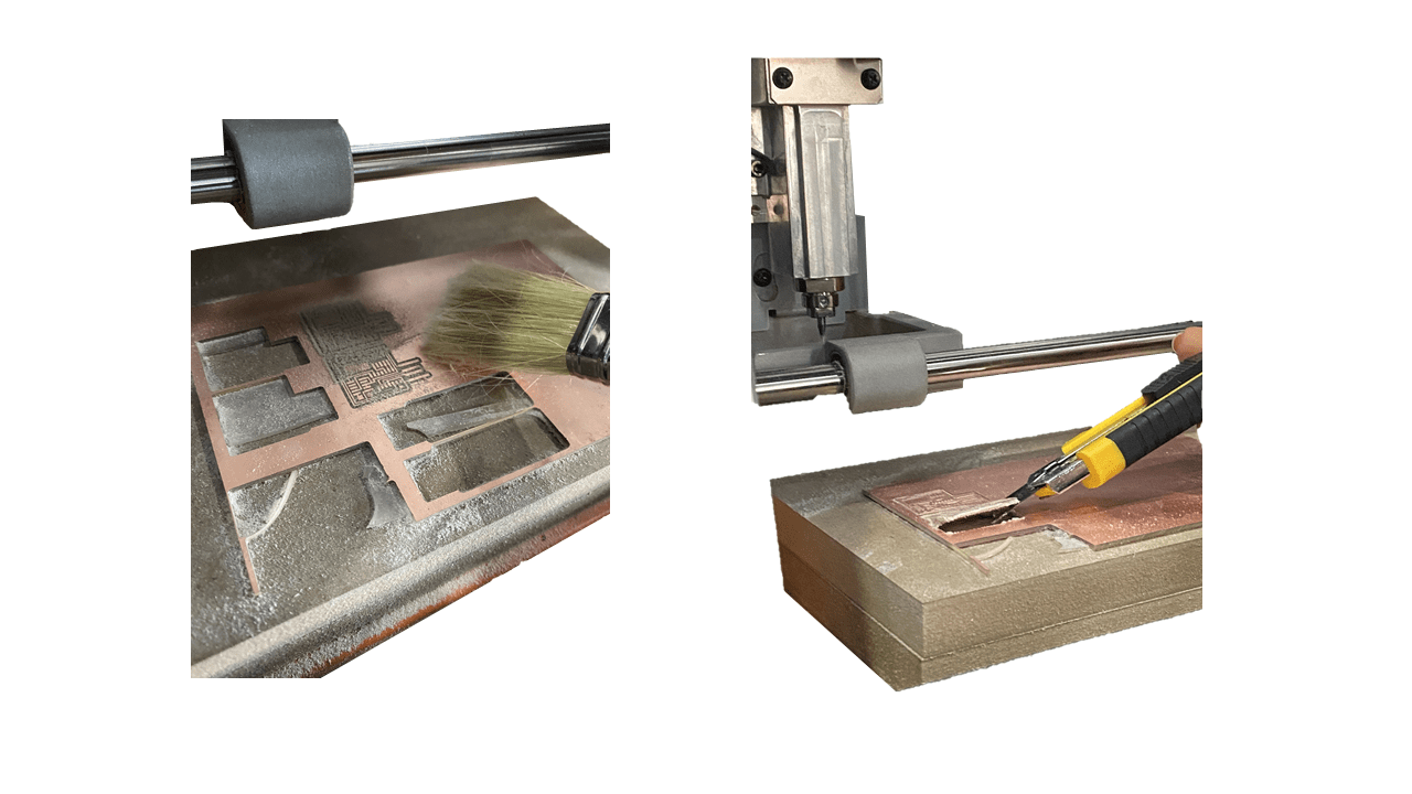
I then started milling using Roland SRM-20 and Mods ( refer to material characterization to see the steps for this process the difference was only on the files choices)
Deburring and cleaning
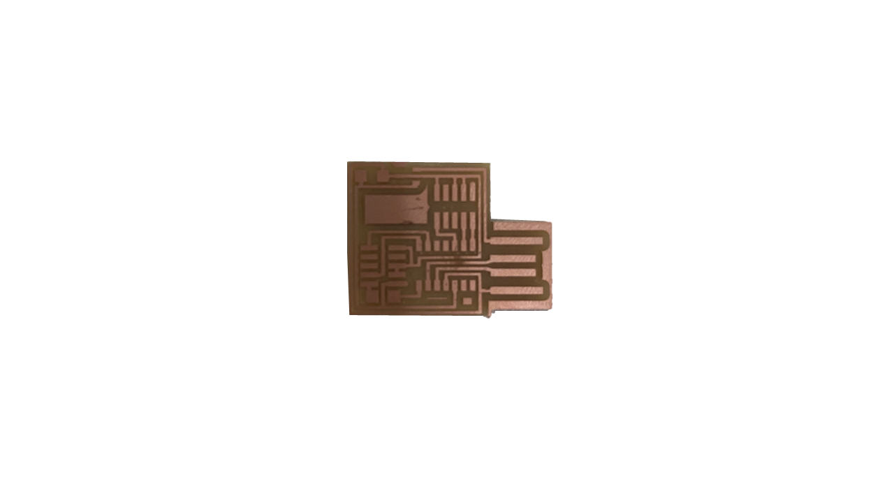
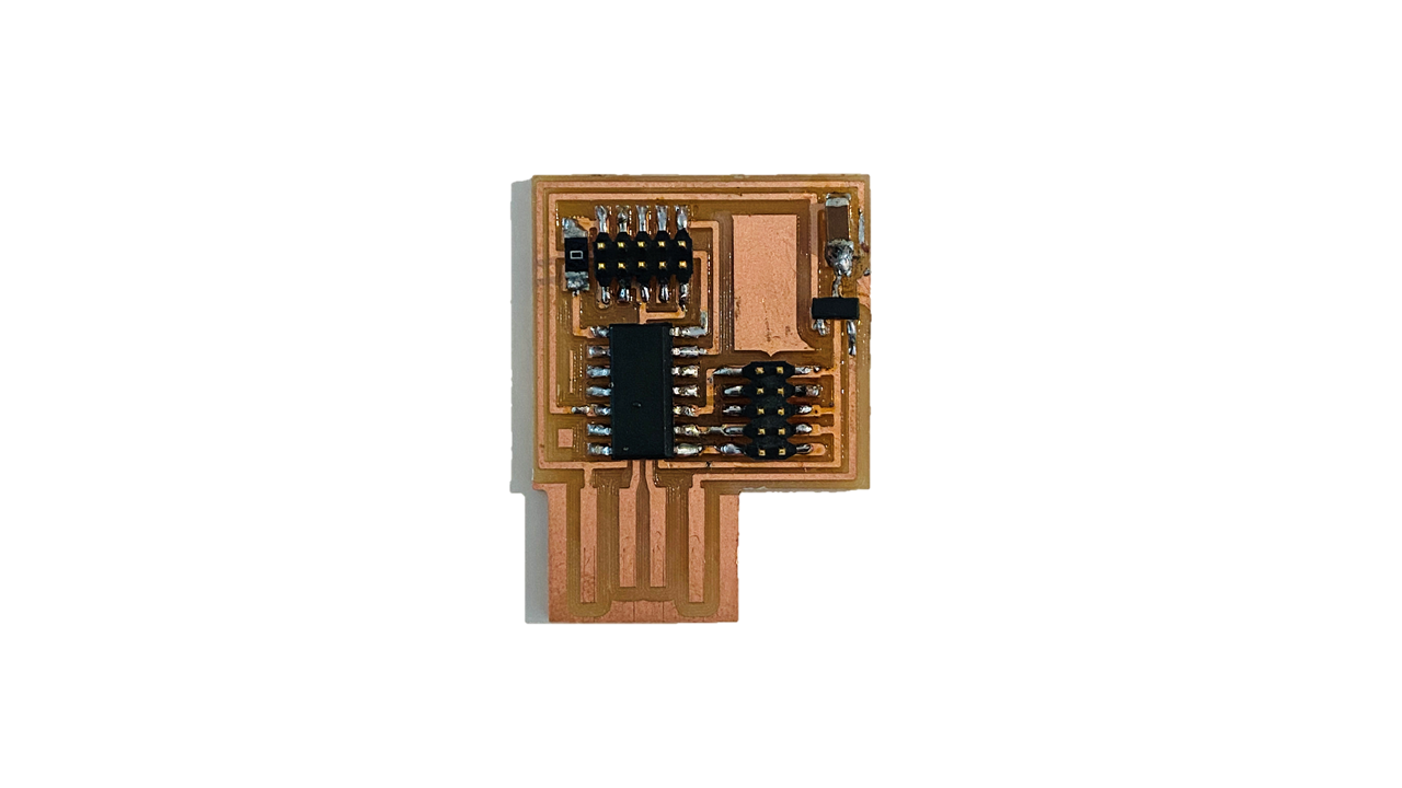
Now my board is ready
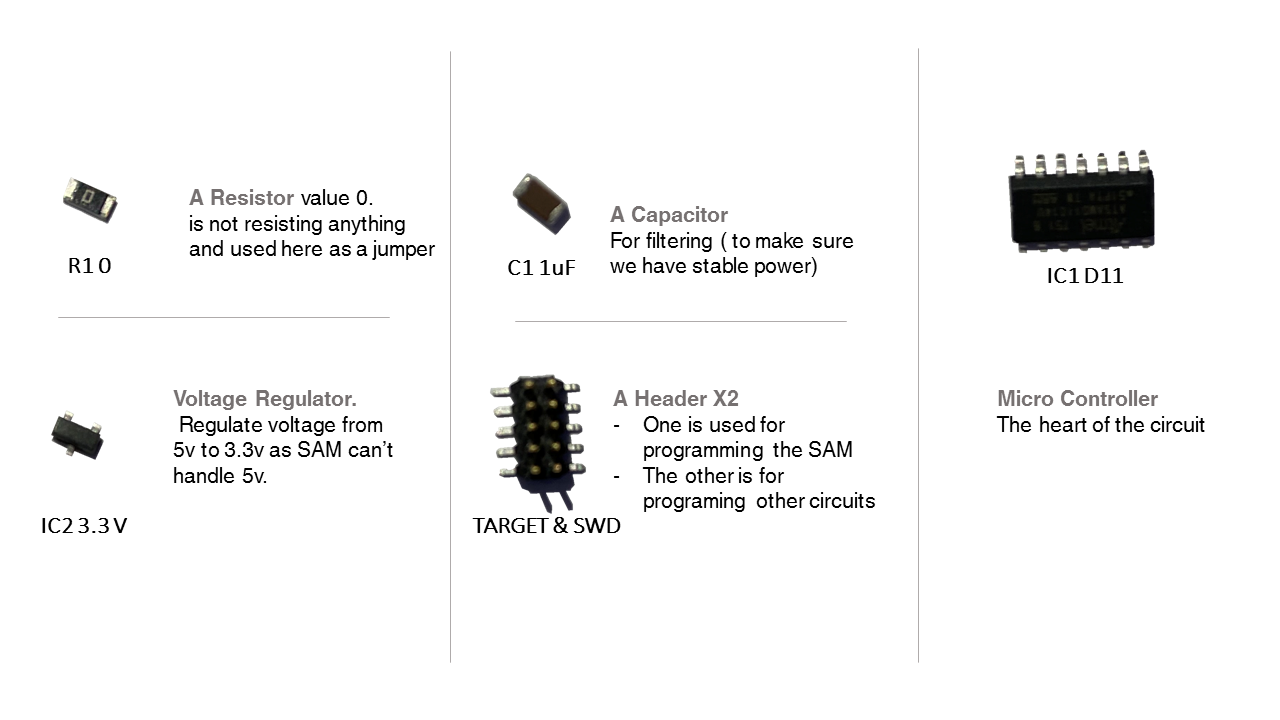
Components
Based on the board image I started collecting the components
PCB Assembly
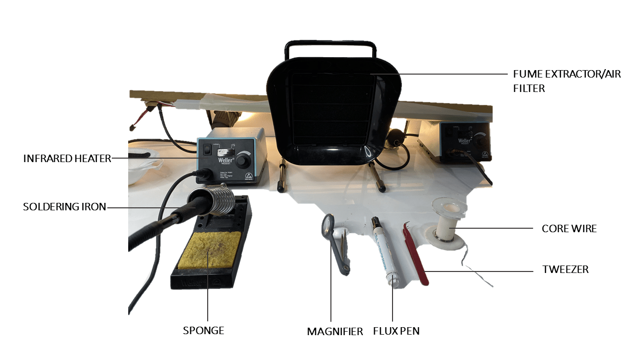
Soldering
To solder is to connect the components of the circuit board to the board.
Here is what a soldering station looks like
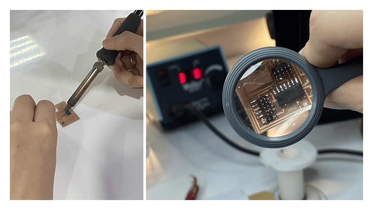
“For me, I found soldering a very soothing and relaxing process. I really enjoyed it.”
After soldering all the components, I then had to check if there is anything unsoldered by looking closely through a magnifier
Now testing if the circuit is well connected Using a digital multimeter
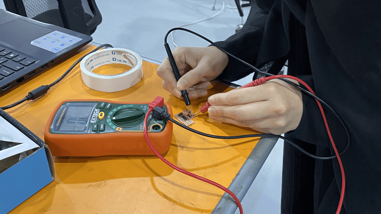
Everything was going well so far
De-Soldering
I noticed the that I had a solder short in one part so I removed it by passing my solder iron on it several times.
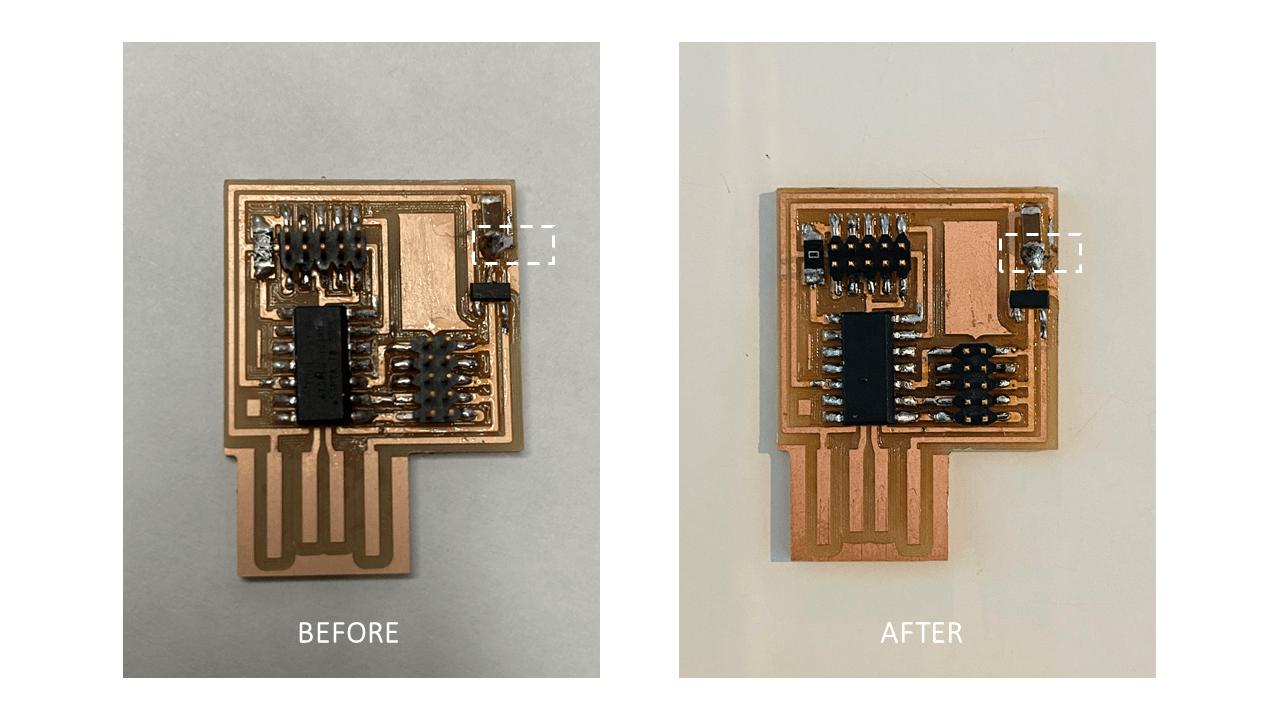
Here is my circuit board
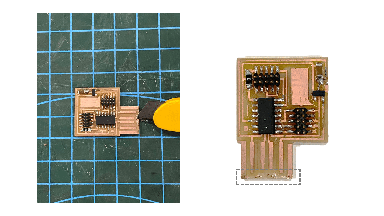
Later on I decided to remove the copper from the bottom part of my PCB to avoid any short that might happen
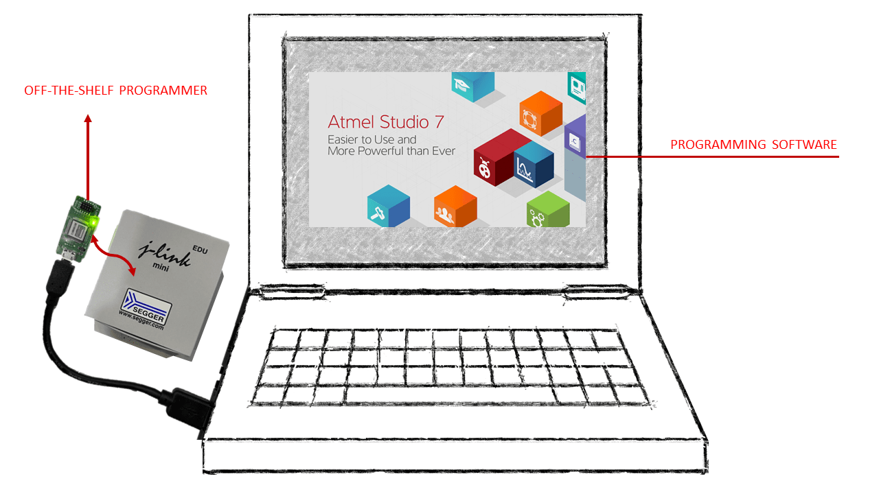
PCB Programming
Programming my own PCB
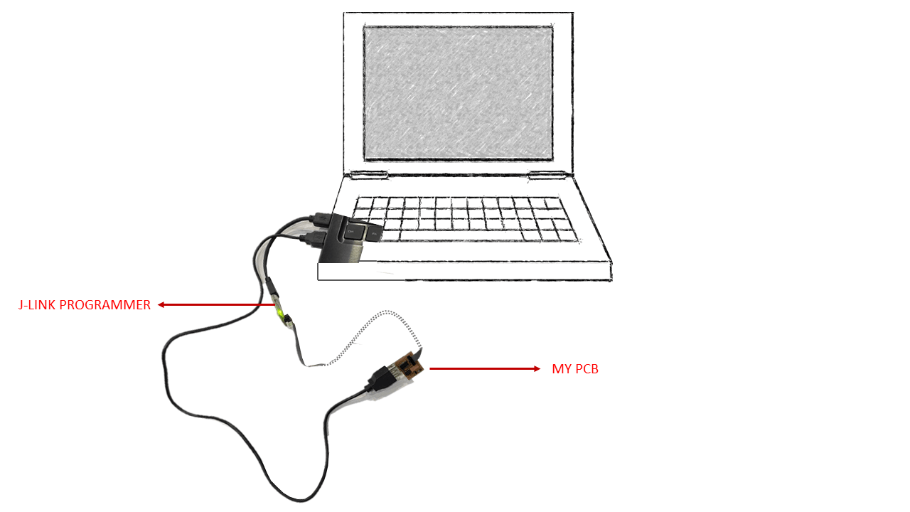
To do so I used an off-the-shelf programmer called J-Link mini (Used for Educational purposes) and I programmed it using “Atmel Studio” as illustrated Below
Programming other PCB
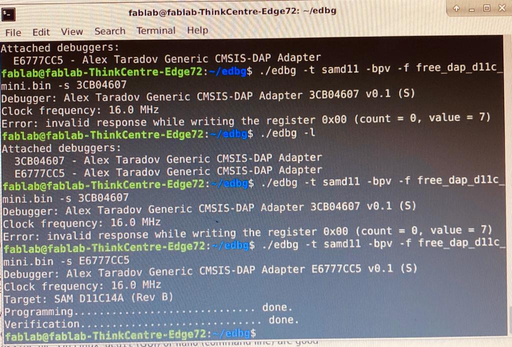
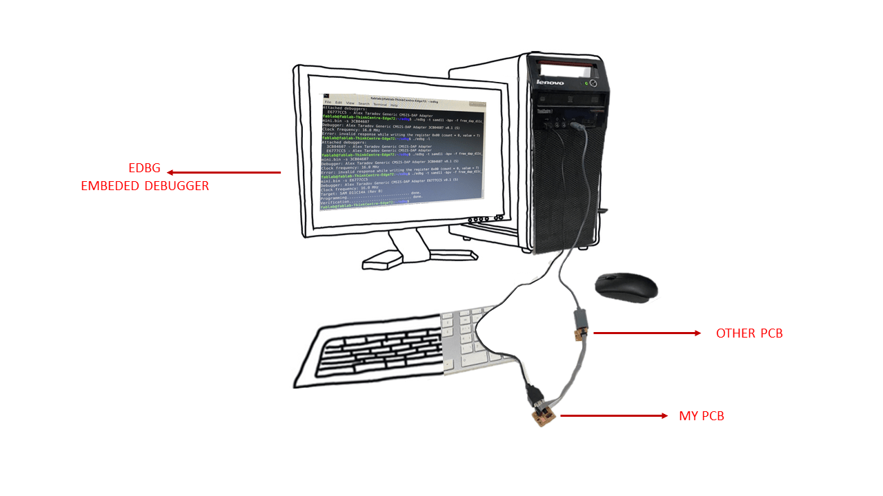
I then programmed another chip but this time the process was slightly different as in this case “Atmel Studio” couldn’t be used . It is used only with commercial programmers. Instead I programmed it using a toolchain that is done in command line (a terminal) ; Edbg. I used one of the labs computers in which it was installed.
- First I had to connect my programmer and the other chip to the computer and to each other
- When I first opened the command line I typed cd edbg ( This is to go to the debugger)
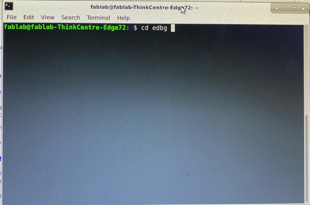
- Then I typed -l ( In order to list the identified PCBs)
- Both debuggers were identified (Mine was : E6777CC5)
- I then typed ./edbg -t samd11 -bpv -f free_dap_d11c_mini.bin -s E6777CC5 ( I used my PCB’s serial number as it is what I want to use as a programmer)
- Then programming started and was completed successfully