15. Molding and casting
Aims
I do not know what to do for this week actually. I am trying to design something maybe not related to my final project. So I decided to challenge myself and try to cast some minimal surfaces.
Group assignment
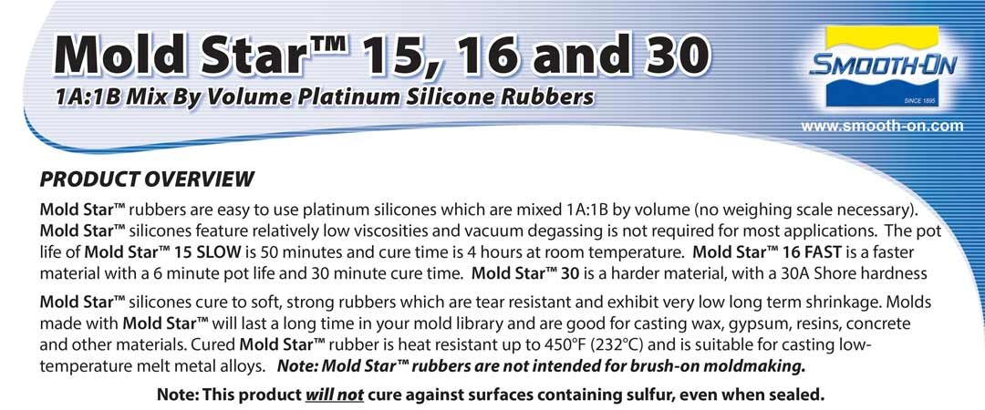
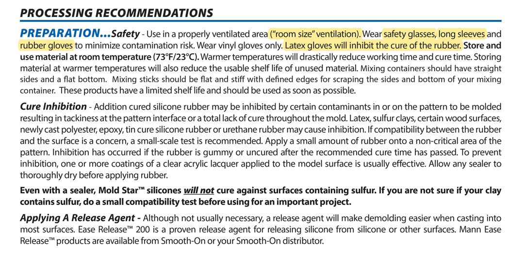
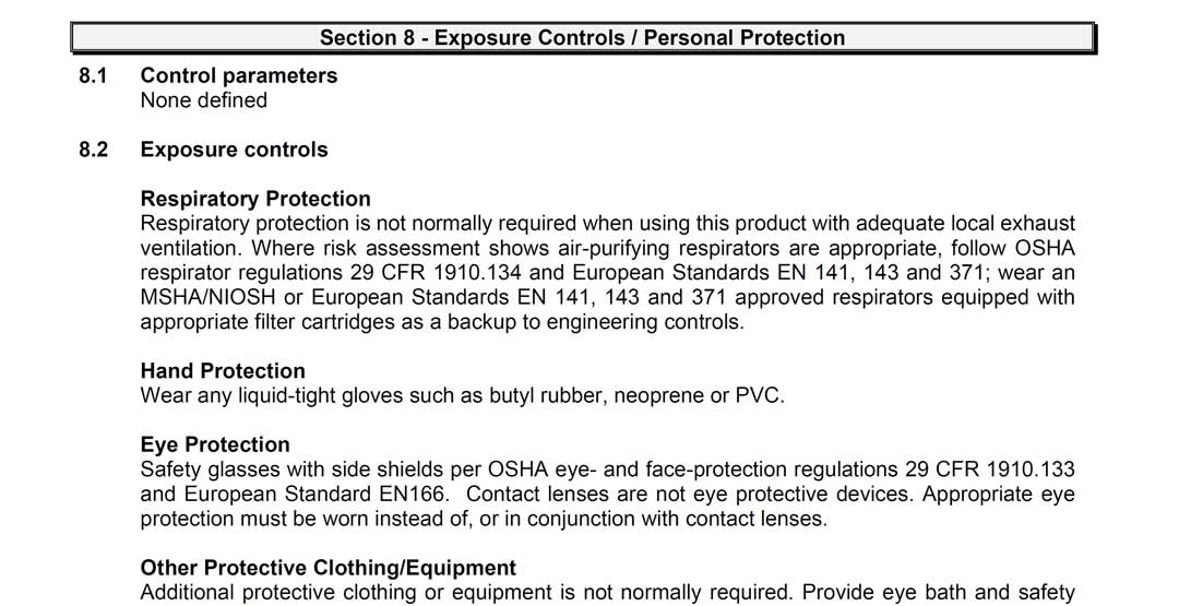
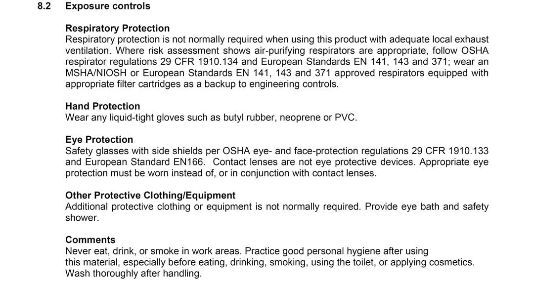
For group assignment we had to review the material data sheet.
So I choose to review silicon from smooth-on. I download the Technical and MSDS document from their website. screen shots from the part that is related to safety measures is been added below.
design
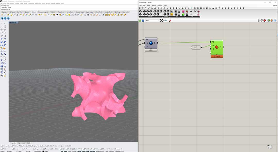
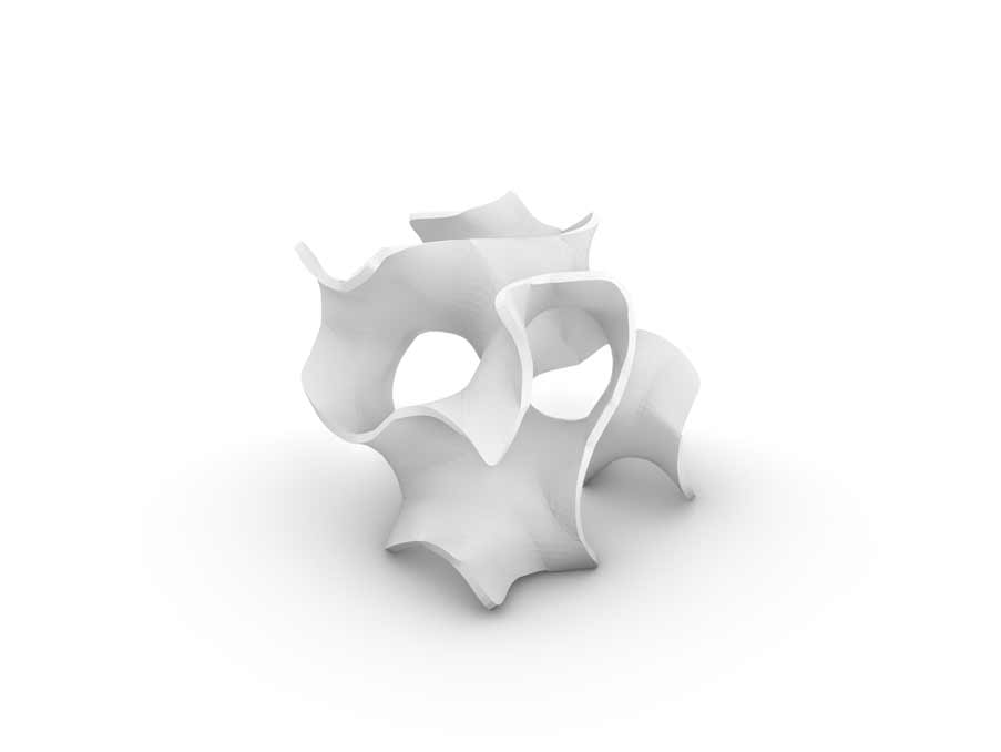
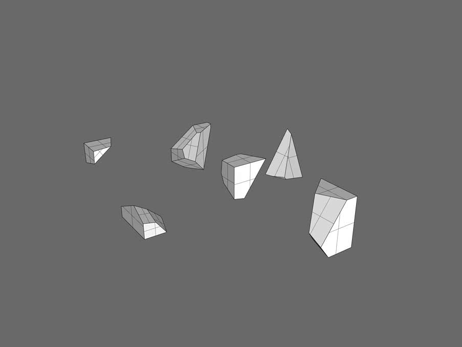
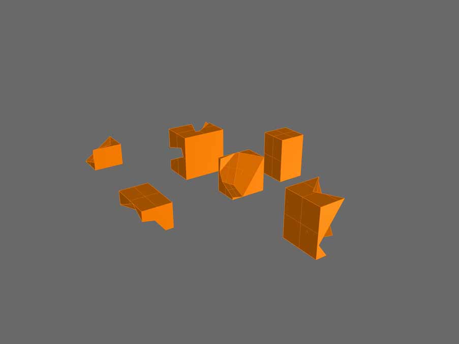
I want to try to reproduce the polyhedron that I designed in 3d printing week with molding and casting technique. I am sure it would be very challenging since it has very small volume and maybe it is not a best design for this technique but anyhow I would like to try it.
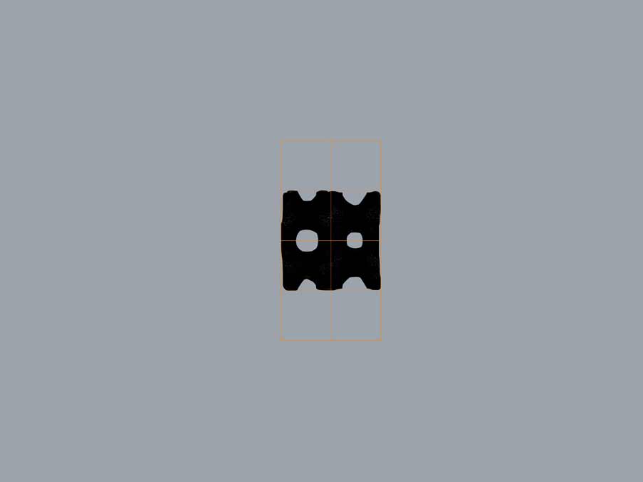
After couple of attempt realized that its not that straightforward process and thought it is better to simplify the design. Hence, I designed a 3D puzzle based on voronoi geometry. But this one also was not as simple as it looks. The challenge is how to dived the mold for the piece in order to avoid the undercuts in milling process. Still haven’t figured it out how but I complete the process of mold design jus by the few pieces that were not problematic.

Final project contribution
For my final project I have tried 2 different method for molding and casting. You can follow up on the documentation from here.
During the final presentation rush, I tested two mold pieces for my final project. But since I have never used that mold for my final project I will use it here as weekly assignment.
design
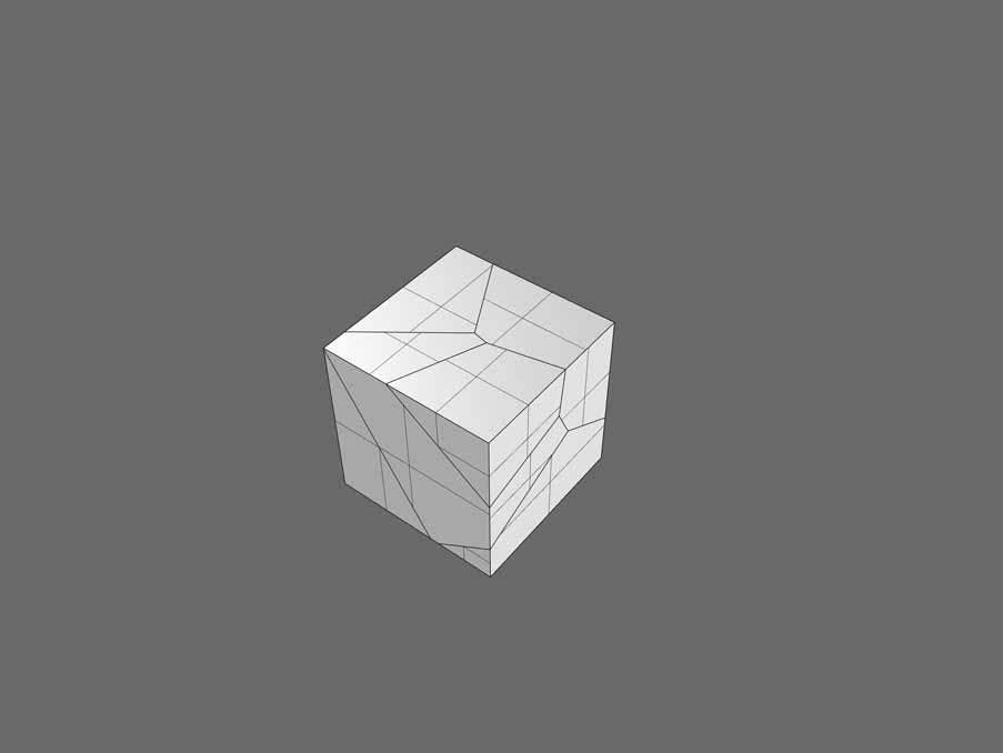
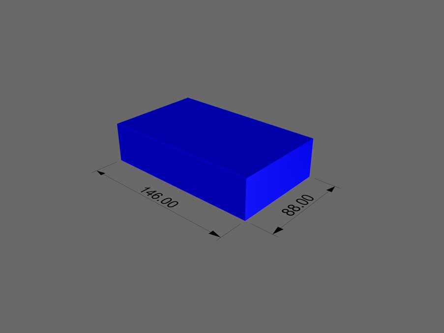
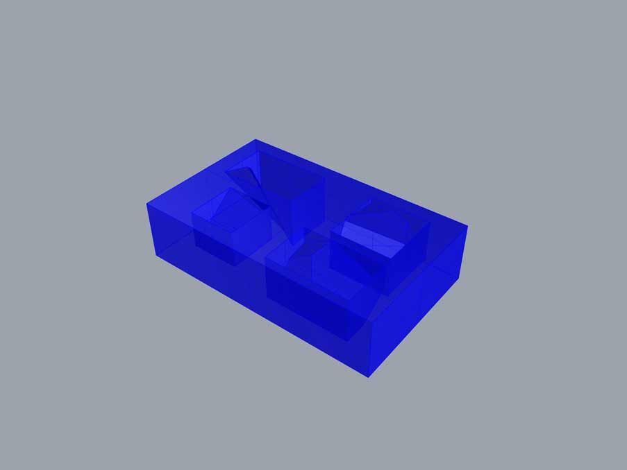
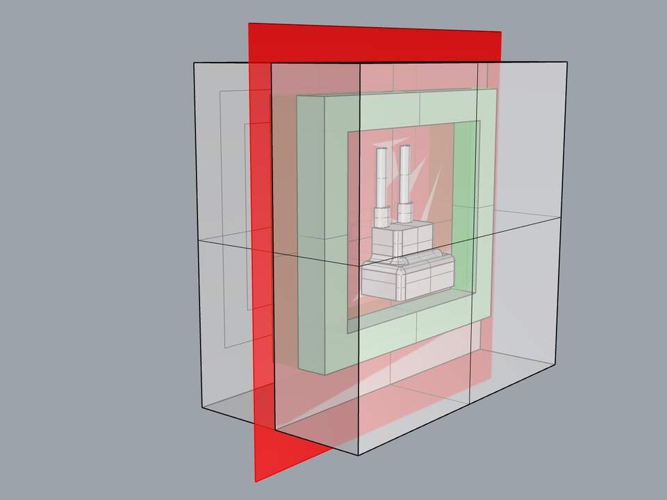
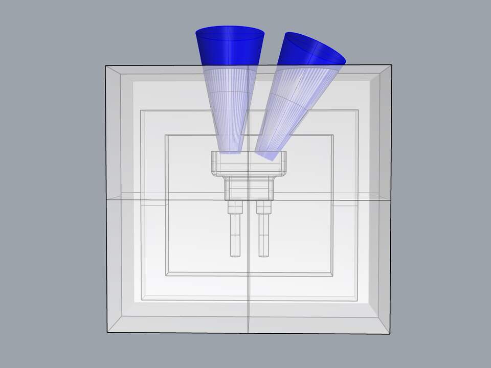
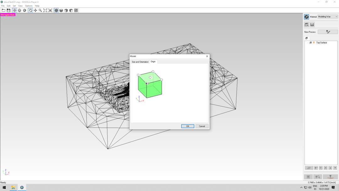
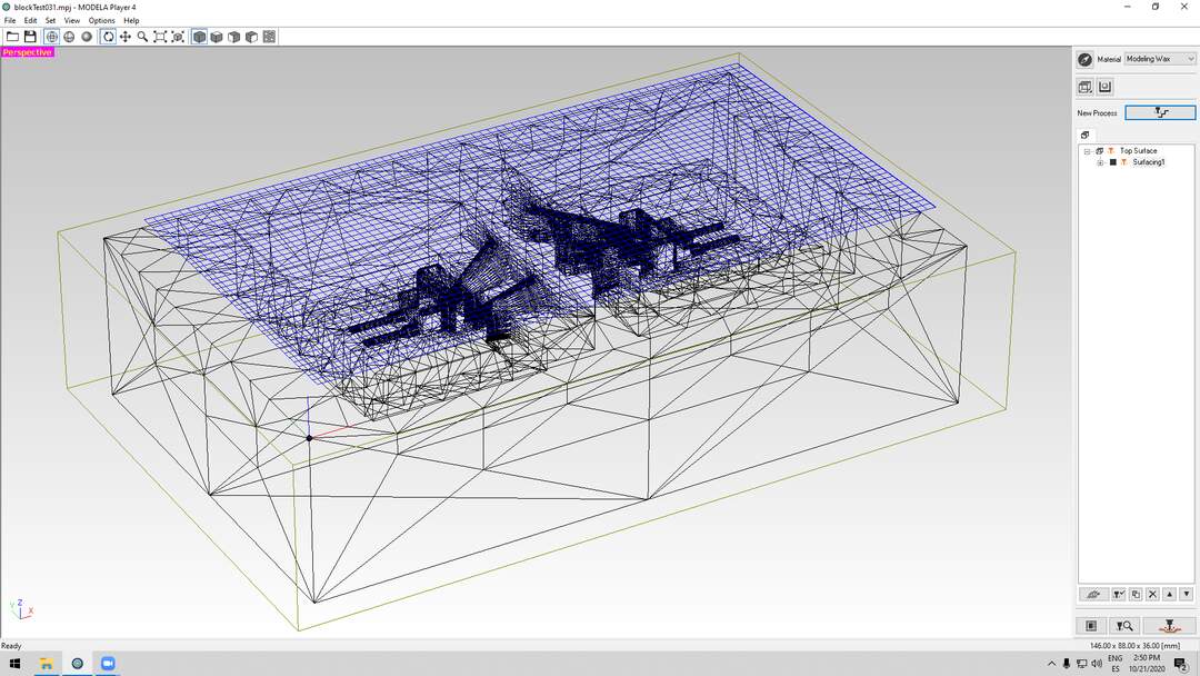
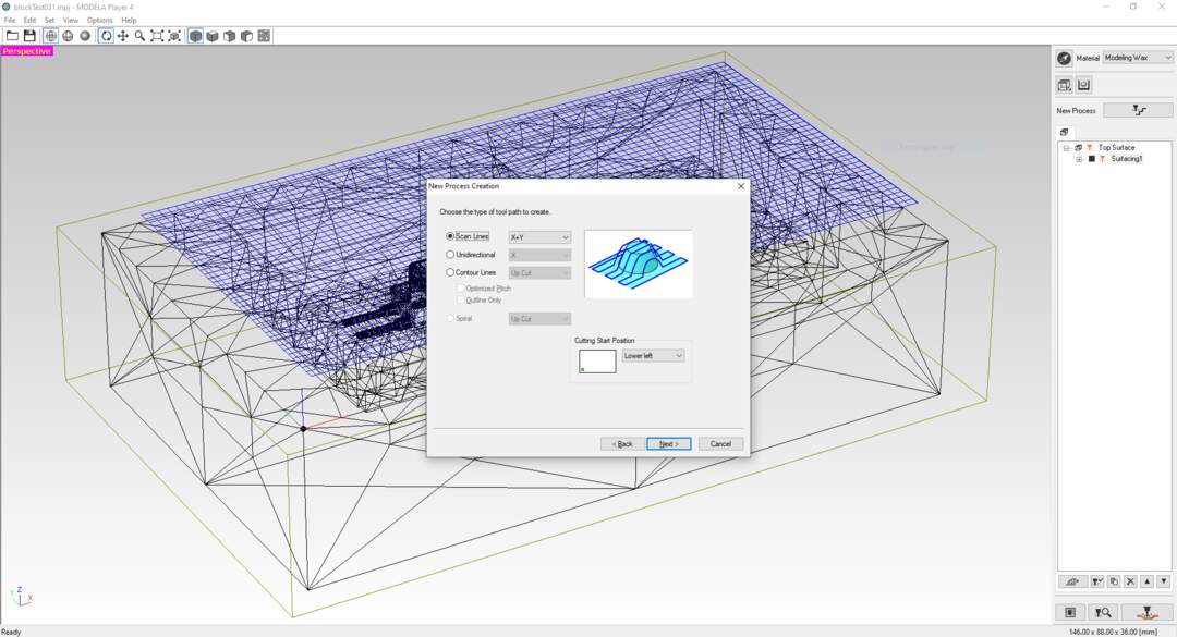
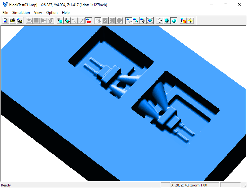
after the design finished. the block has been subtracted form from a cube to make a negative form. after that to prepare the two side mold, the cone shape geometry has been considered for puring the material and air release. Furthermore, to make sure that the molds will fit together perfectly, A 3d frame added to the around of object. After this step I slice the negative to have it as two part. then with considering the margin (10 mm from the walls , 15mm from the bottom ) I place these pieces on the wax to get the position of it for milling process.
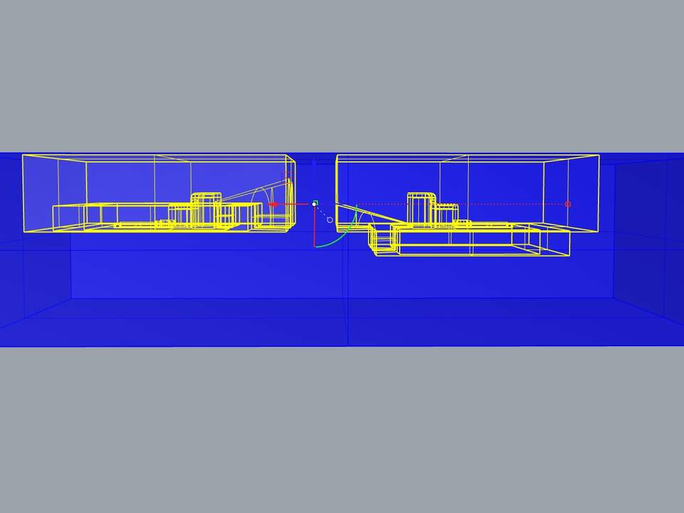
You can see the final model for milling process here.
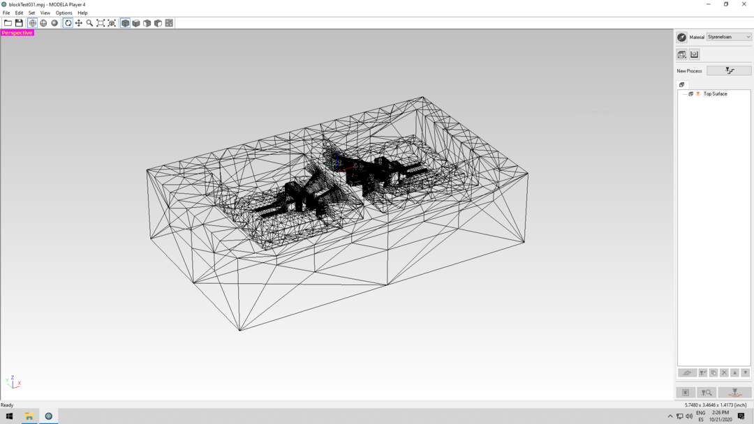
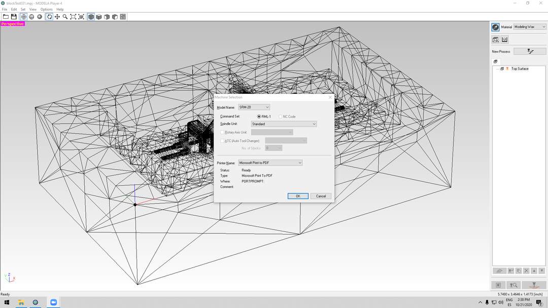
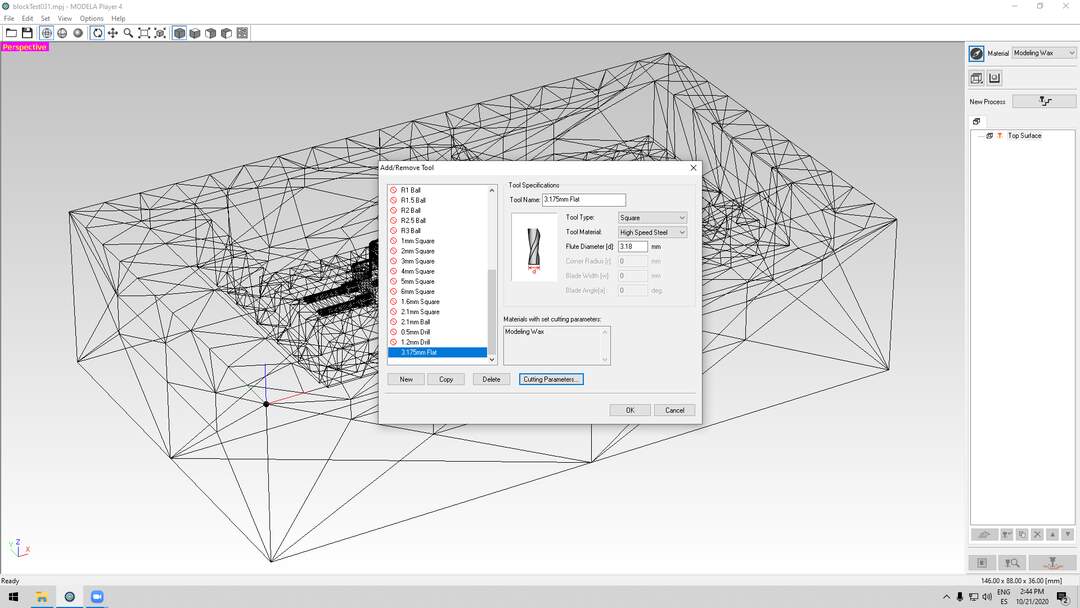
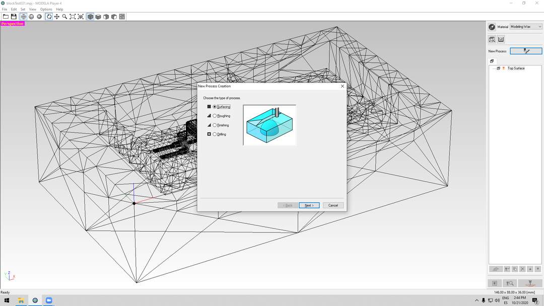
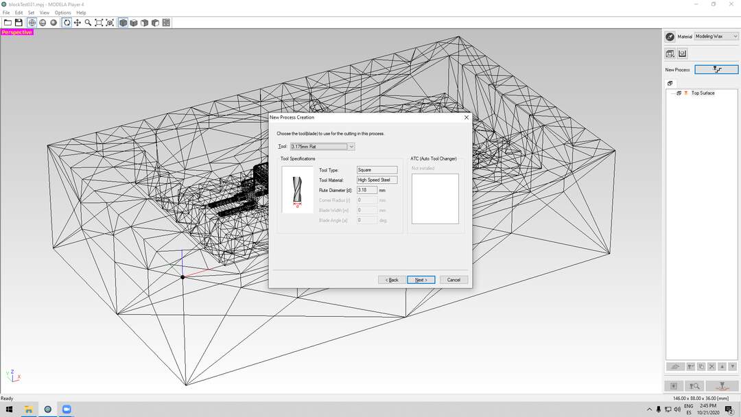
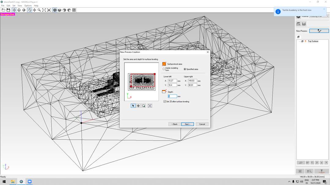
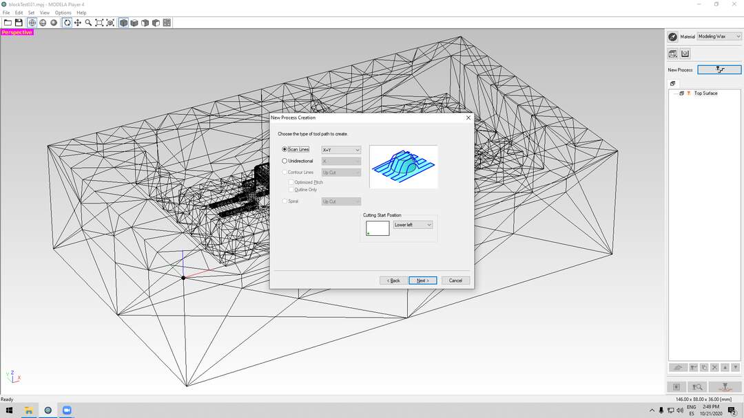
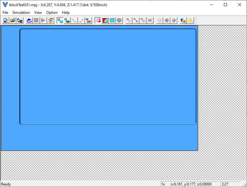
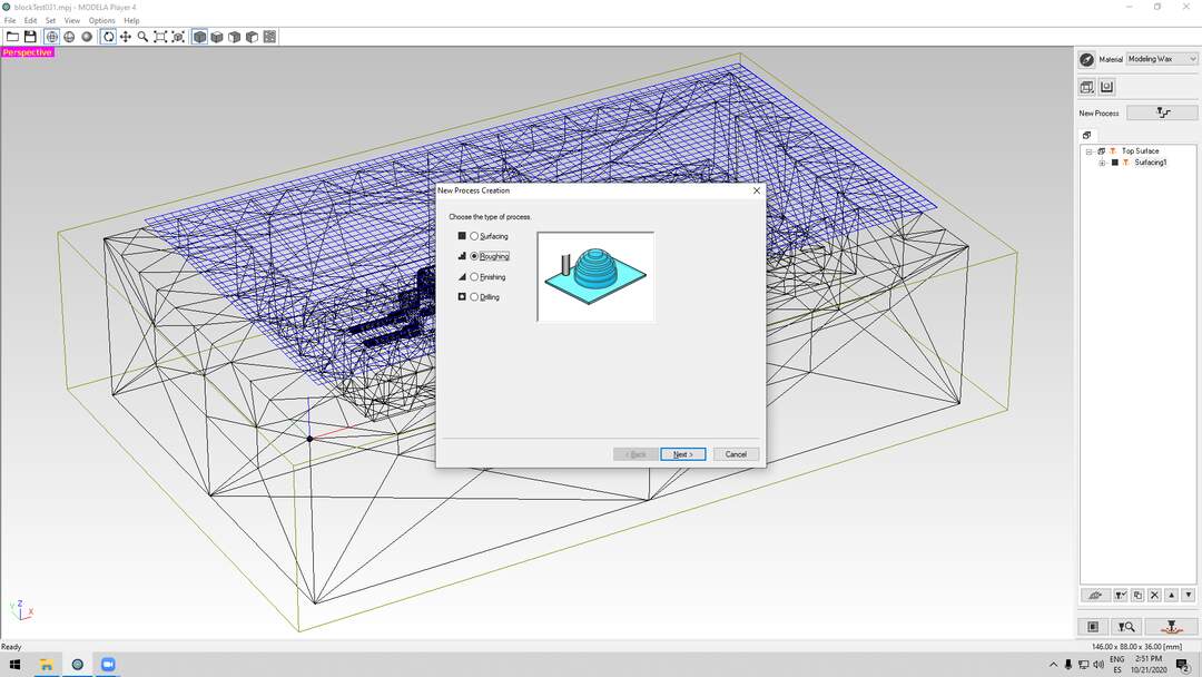
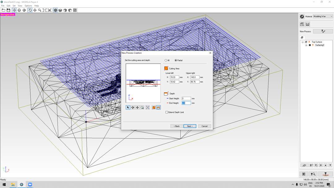
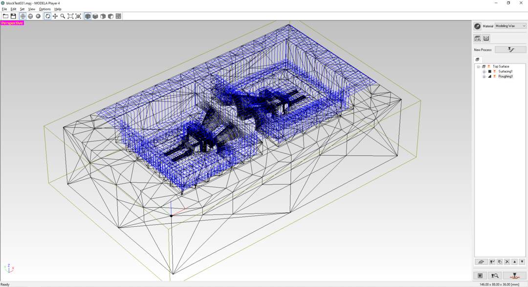
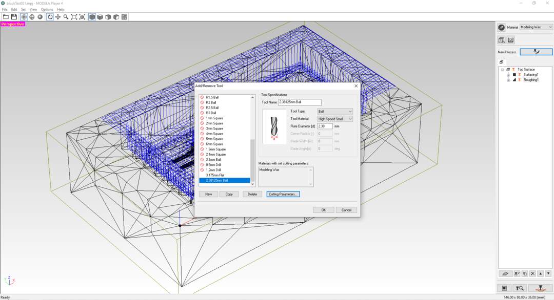
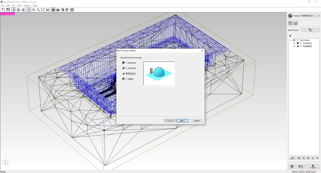
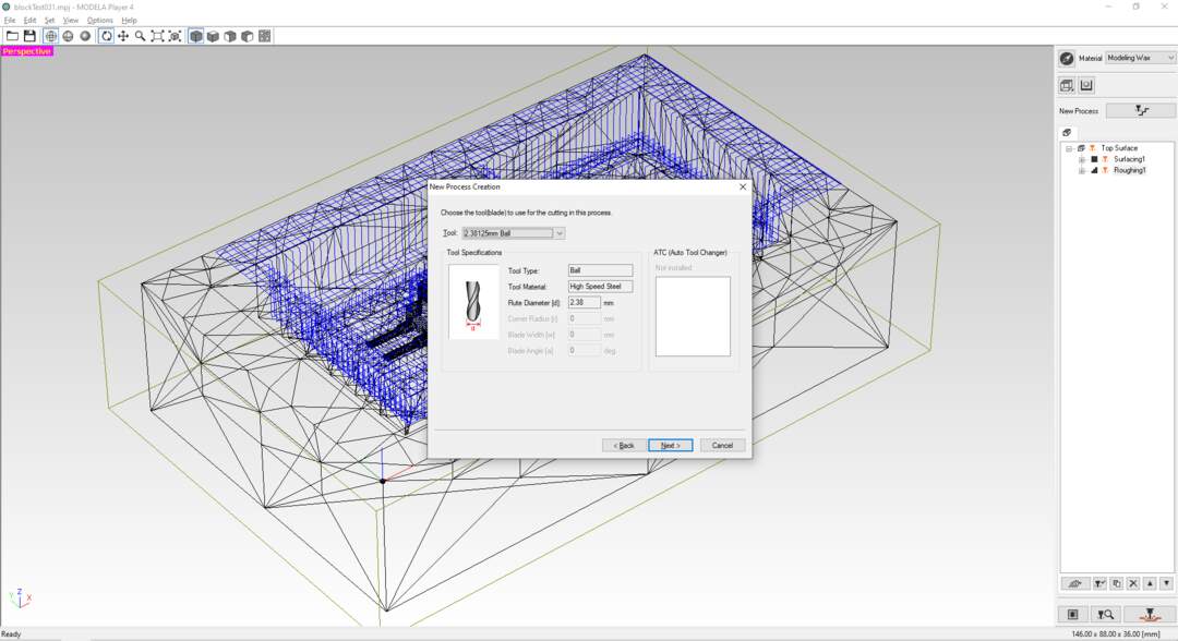
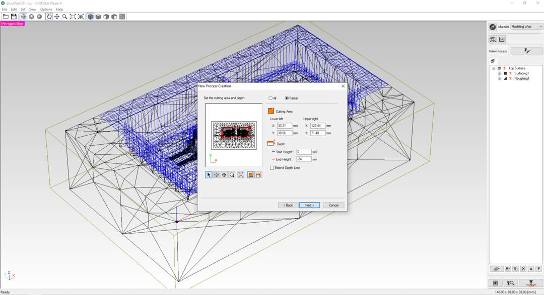
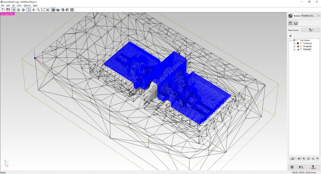
CAM with SRM-20
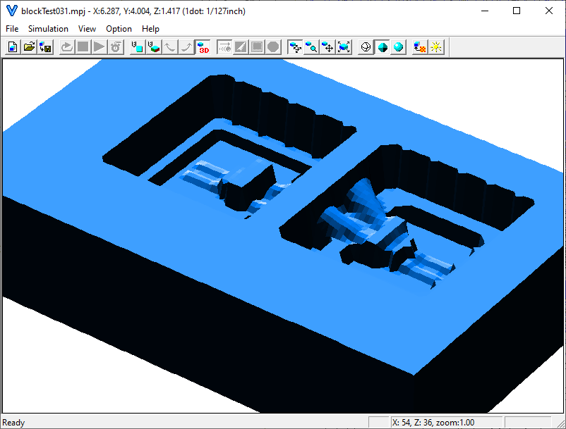
Then I have used modela4 software to generate RML code for SRM-20. Unfortunately I do not have it documented for this model. But you can check my documentation in final project which I linked earlier. During making file I did some mistakes and tricks that I want to point out. First since I was using recycled brick of wax I had to do a surfing strategy to flatten the top part of the mold before doing anything else. I did surfing but was not deep enough so at the center of the brick there was a small uneven surface which I could avoid. The other trick that I have used was doing the finishing just in the part that actually matters the most. this trick save hours of milling from the whole process.
video of machining
You can see the video of the machining in this link.
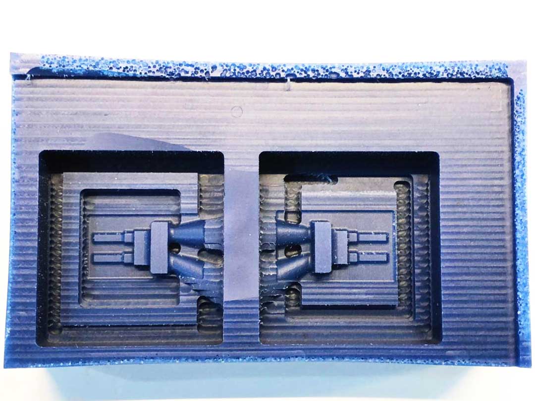
The look of the finish pieces of wax after machining.

Embedded electronic
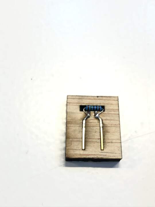
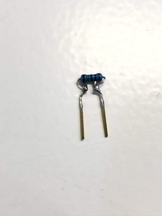
One of the technique that I used in my casting was embedding a electronic component inside my mold. I needed to add resistor to each block to electronically code them. So whenever I insert them into my board it can be recognizable for the processor. For more information on this please check my final project page. To do this I have used trough the hole resistors. In order to have more control on the legs and have them stiffer, I solder a male terminal to each end of the resistor and eliminate the extra legs. For having all of the resistor in a same shape I made small mold which can hold resistor and the pins in a same level and straight so I could solder them with more ease and precession.
Casting
The casting fast silicon was very easy. You have to pure 1:1 proportion of each solution and mix it very well. the currying process will start in 6 min so you have to pure it in to mold before it start solidify.
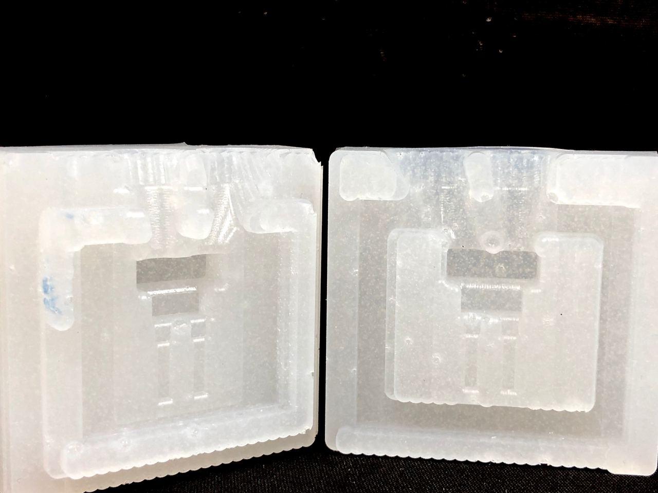
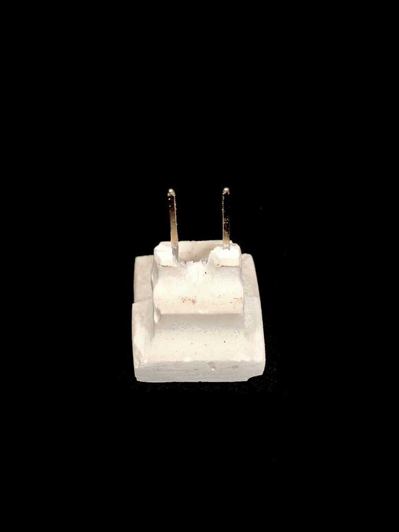
As you can see the result was not that successful. The reason is that the mold is very small and it bending while I am pressing two side together for casting process. Also it is very hard to shake the mold to remove the air bobbles.
You can see the casting video in the following link
conclusion
I think the main reason that this 2 side mold is not working is that it is very small and the silicon is very flexible. So During the casting the pressure to keep the mold part together exceeding and closing the narrow parts of the mold. If I put less pressure there will be small shift in the boarder of the piece. I it would be the best to use harder silicon for making the mold. Also for embedding the resistor I think one side mold was easier and cleaner then two side mold. you can find the process of one side casting the same component in my find project page.
class note:
mold 3d milling much more accurate then 3d printing
soft mold- hard cast hard mold- soft cast
if you can melted it you can cast it
Machine wax HDPE 200 1468836
don’t design thin shells air problem \ milling problem centering the mold
material safety personal safety equipment material datasheet