17. Machine
Aims
We start to design a 5 axis machine base on SPML machine.
3D CAD Design
I started the design by making a parametric configuration of mechanical parts to get a better overall sense of the machine and have some visual understanding of axis range of movement. After that I start to place the actual geometry of the parts and design a raping for the system.
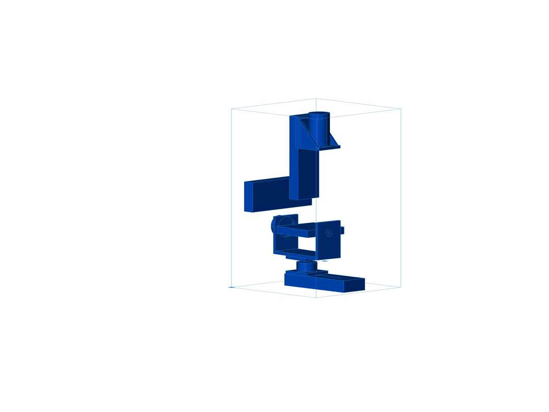
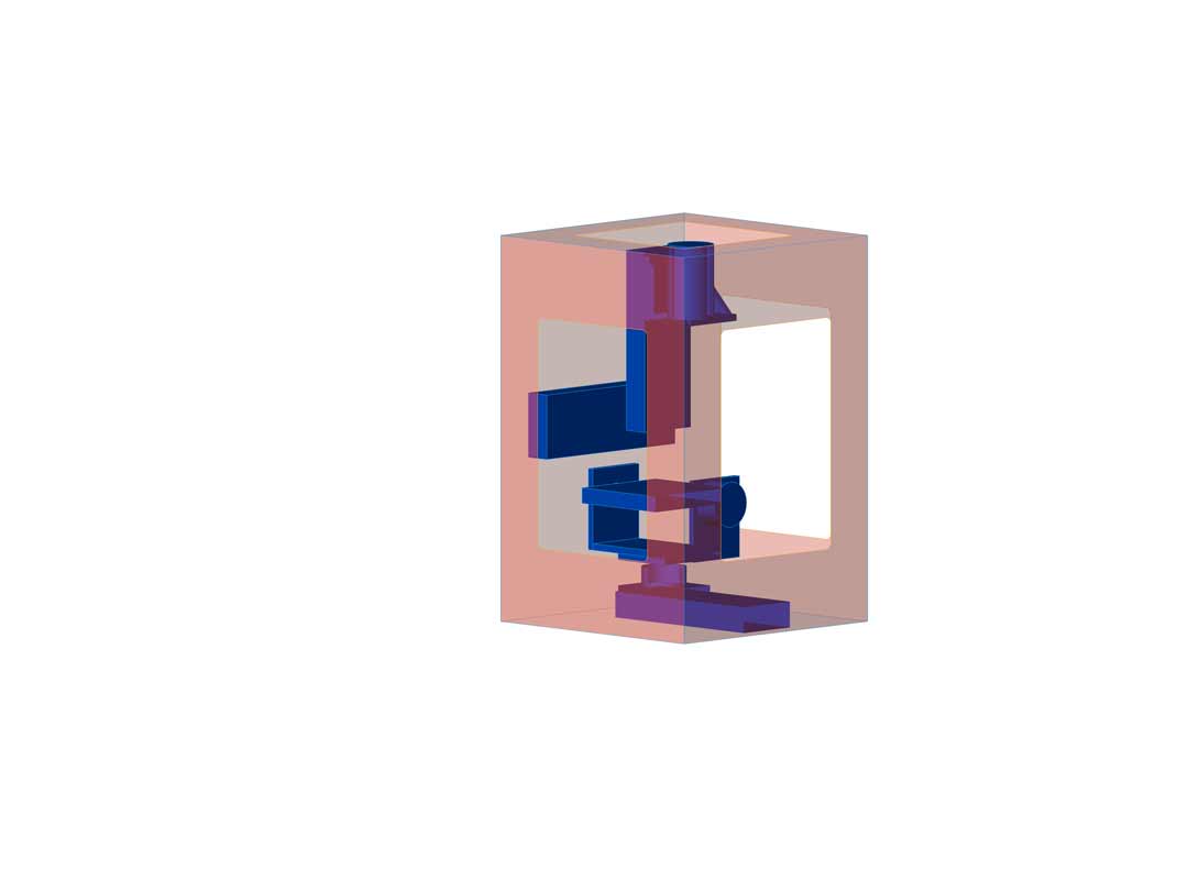
Extra Axes
After finishing the frame of the machine I have realized that my extra axes design include a axes same as the spindle. So that axes would not be that much help to the system. Therefor, I had to redesign that part.
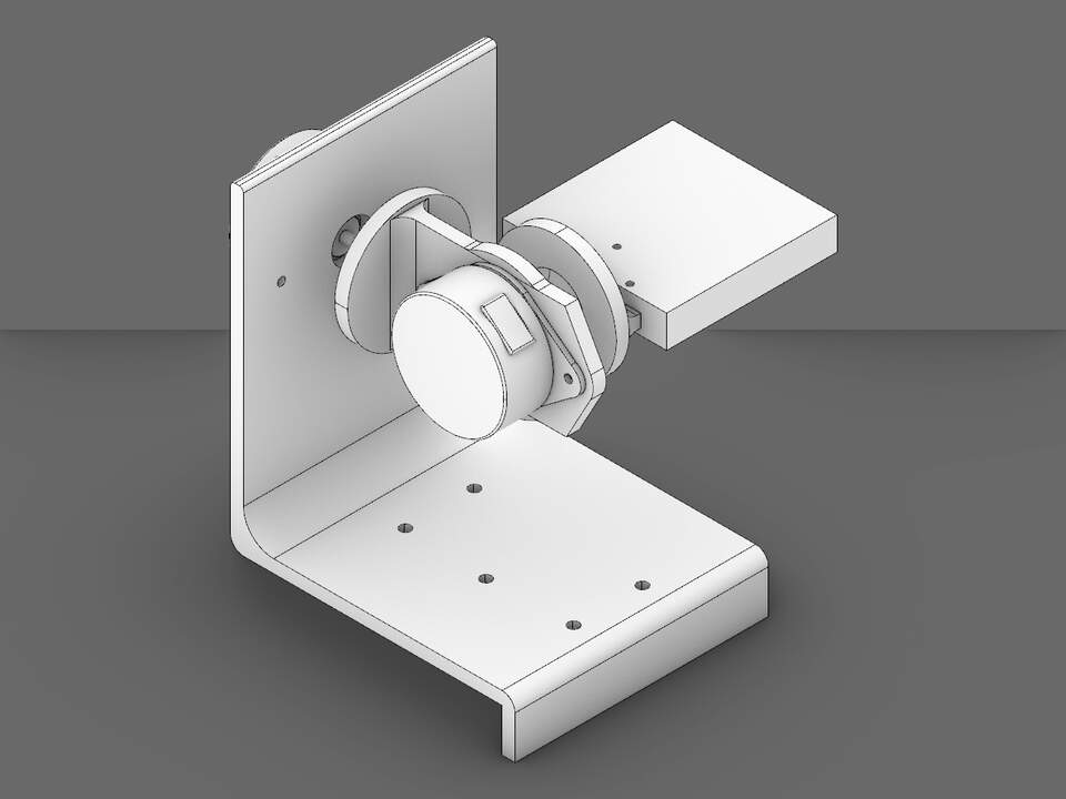
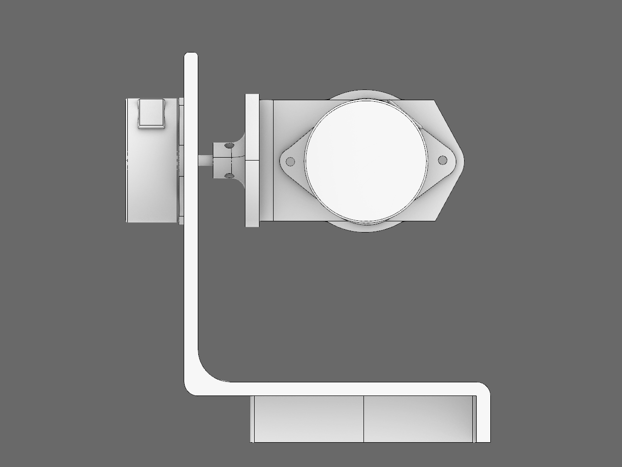
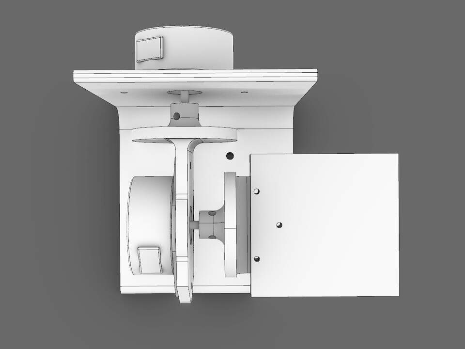
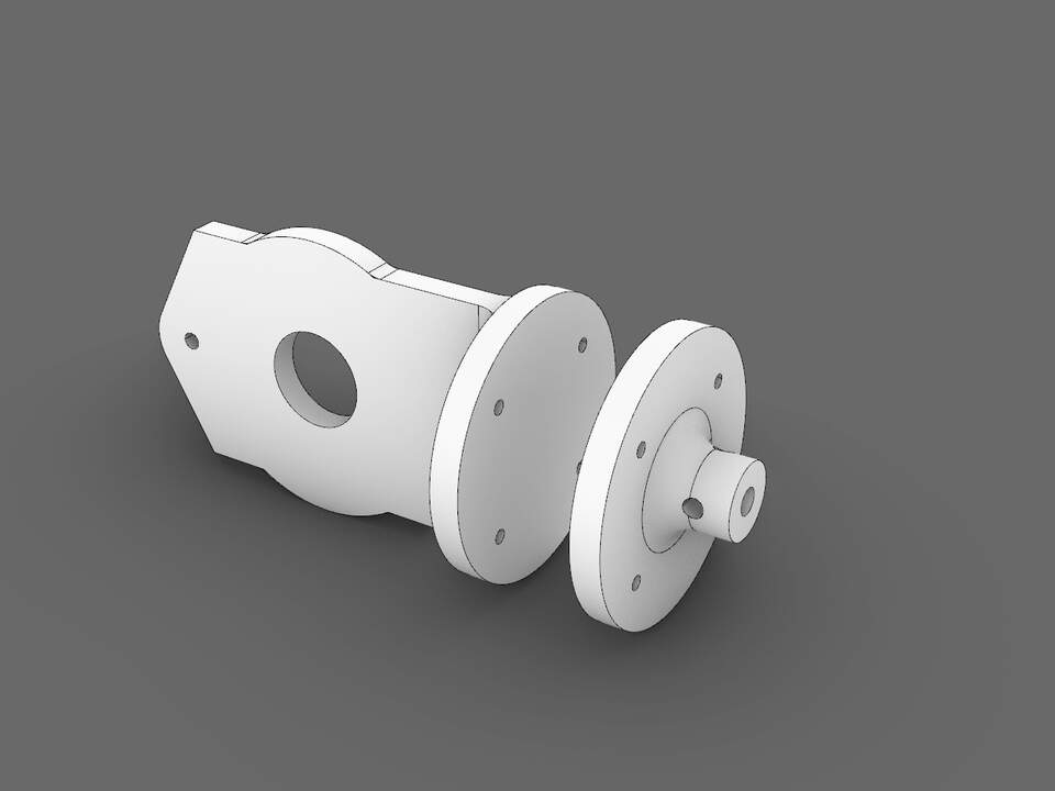
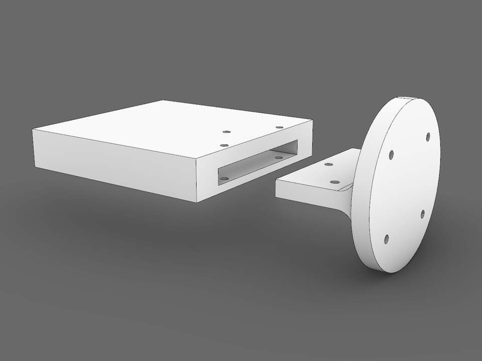
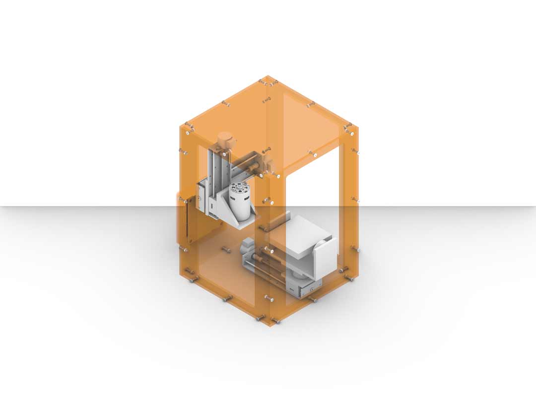
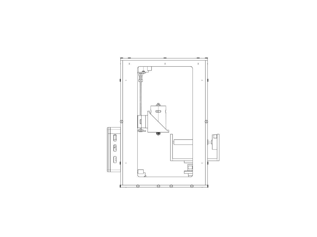
3D models
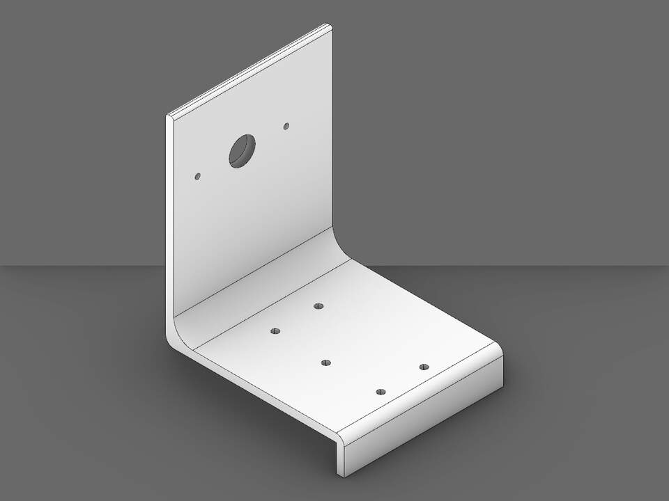
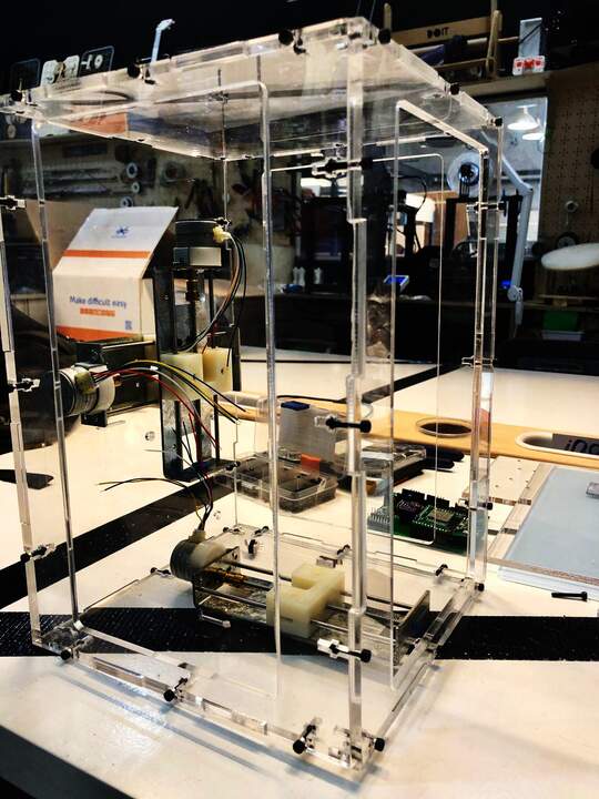
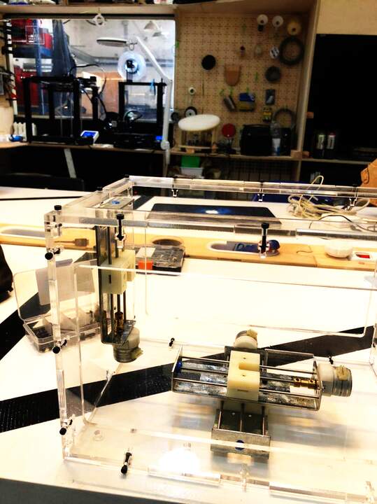
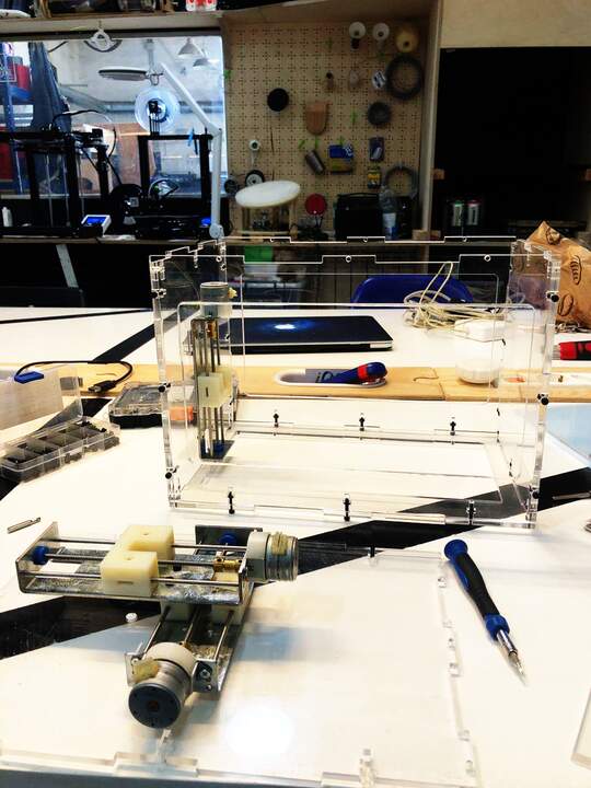
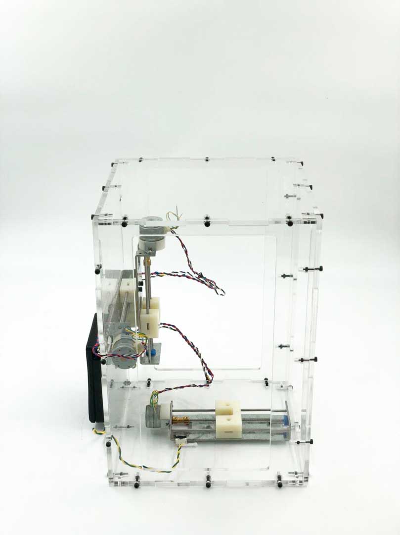
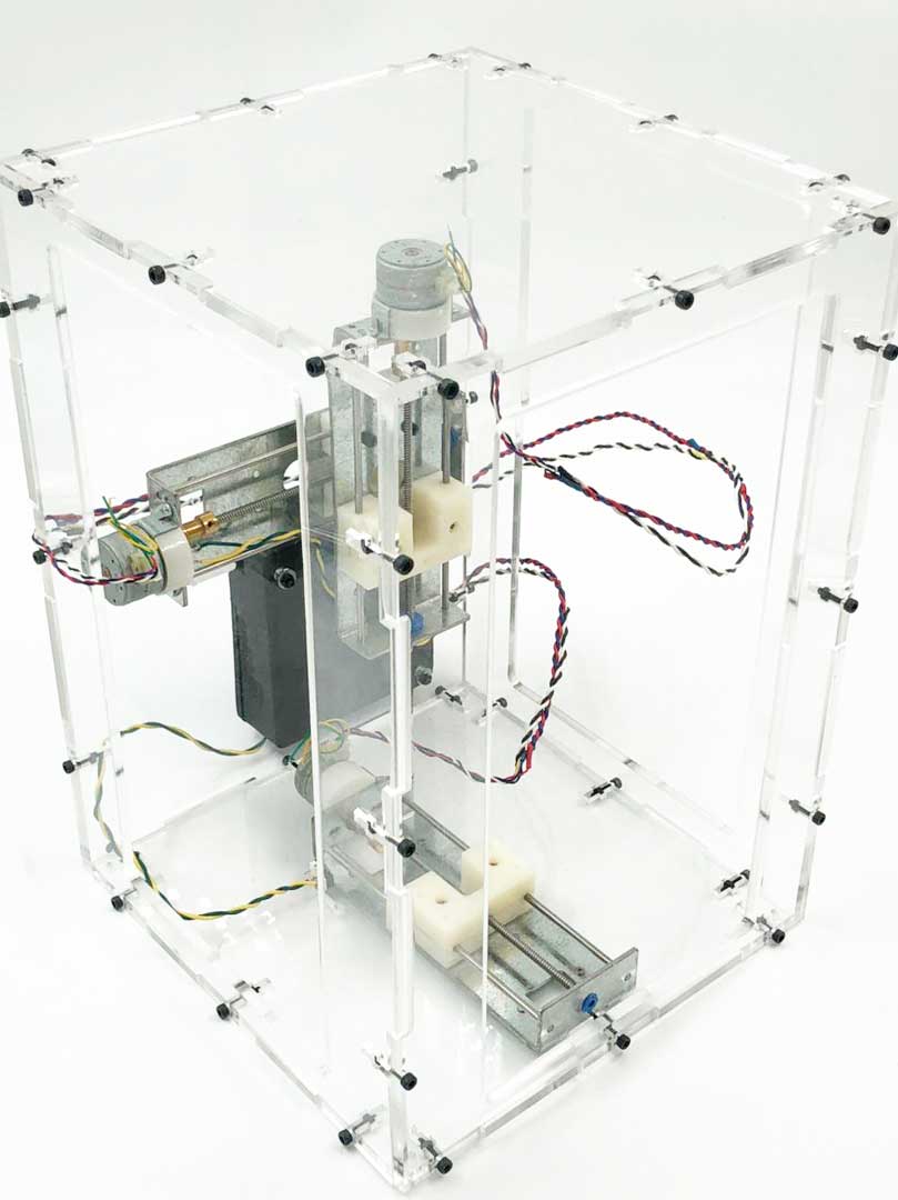
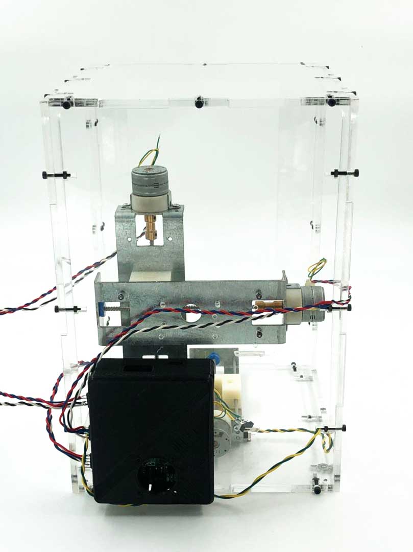
Fabrication and assembly
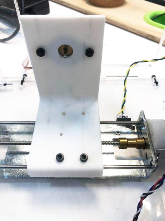
The fabrication of this machine involves laser cutting and 3printing. the laser cutting file prepared to be cut on the acrylic. In the design considered to assemble the pieces with three screw in each edge to make it stable and rigid. the only problem that I faced was the limit sensor position on each axes. the problem was that the screw size that we had in the inventory was not fitting in the spacing that I had considered. To fixing that I had to use small drill and make hole for screws.
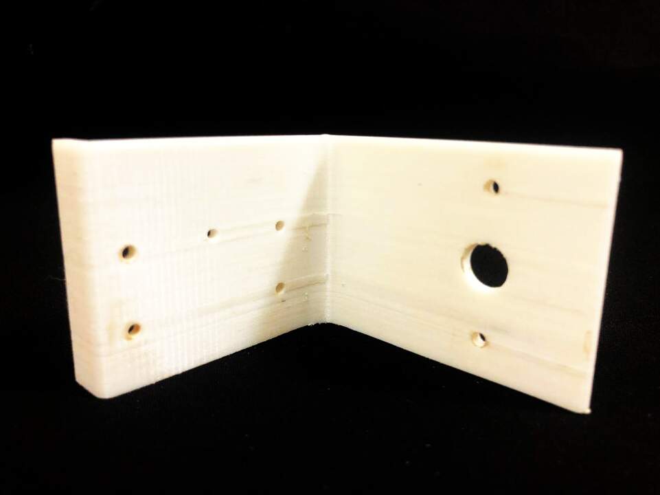
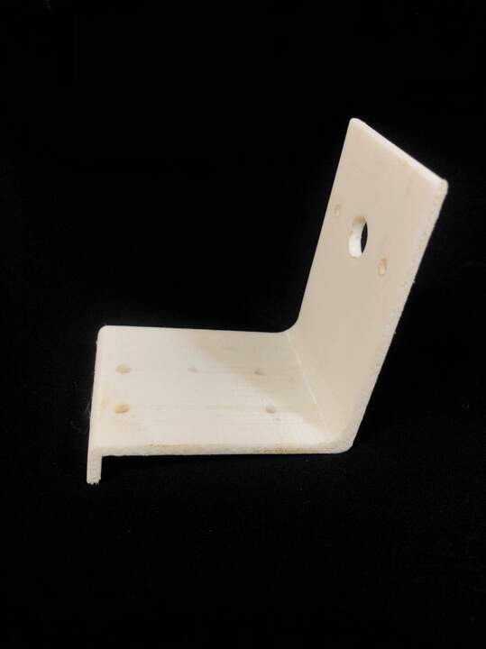
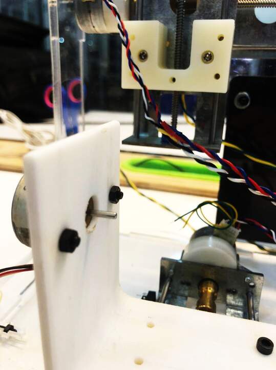
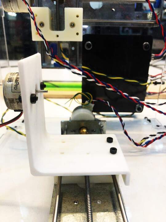
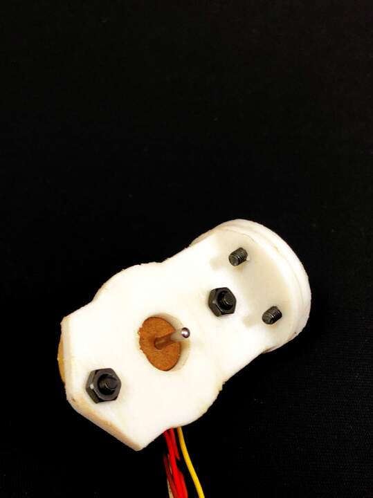
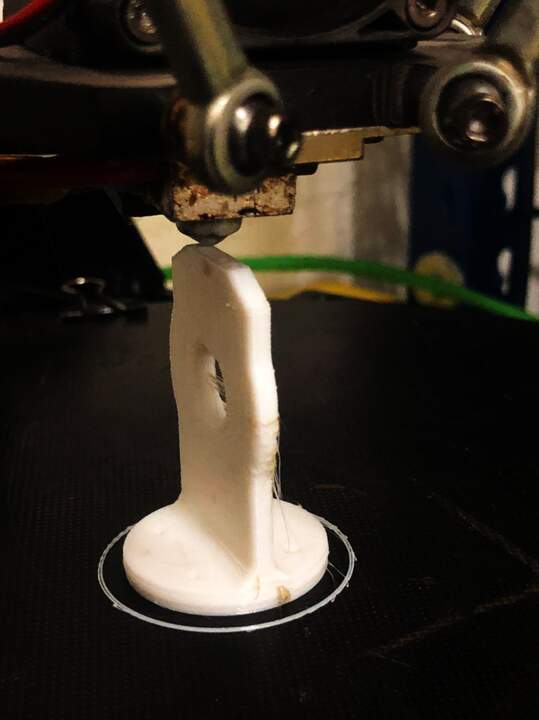
Extra axes fabrication
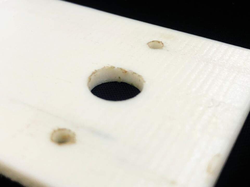
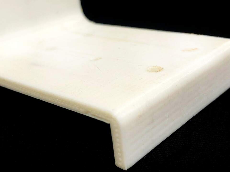
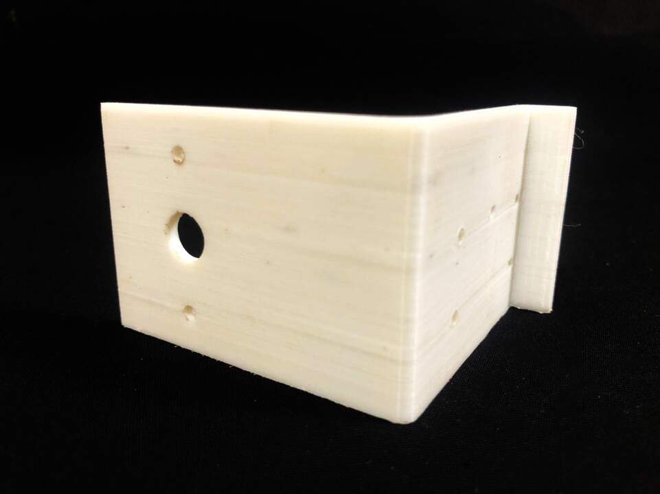
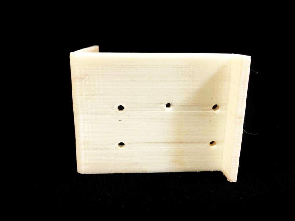
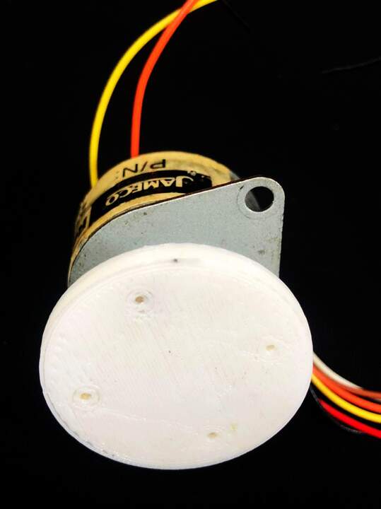
I used 3d printing technique to fabricate the extra axes. I have used FDM with PLA material. The thickness layer of the prints was 0.15 and the temperature was around 210C. It happened 2 times that the prints failed at the end. I do not have a image but seems that bed loosing temperature and the layers at the end are not getting attach to the piece. The post process for each pieces consist of hole making for screws with 2.5 and 3 mm drill bit and sanding. there is a problem that I am facing now for connector piece as shaft coupler. It is not keeping the shaft tight and the pieces start breaking. I will need to 3dprint this part with SLA printer.
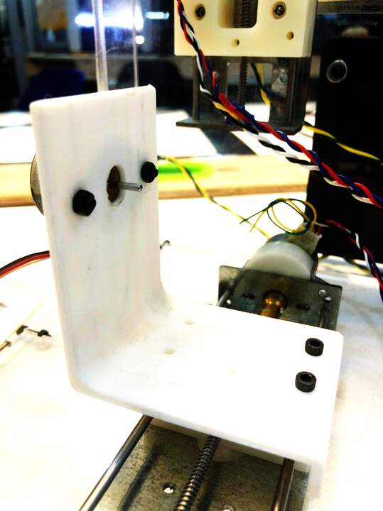
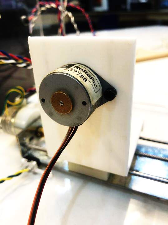
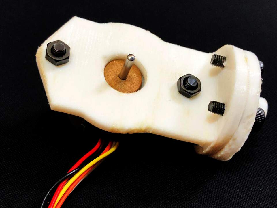

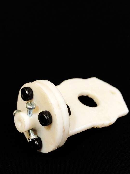
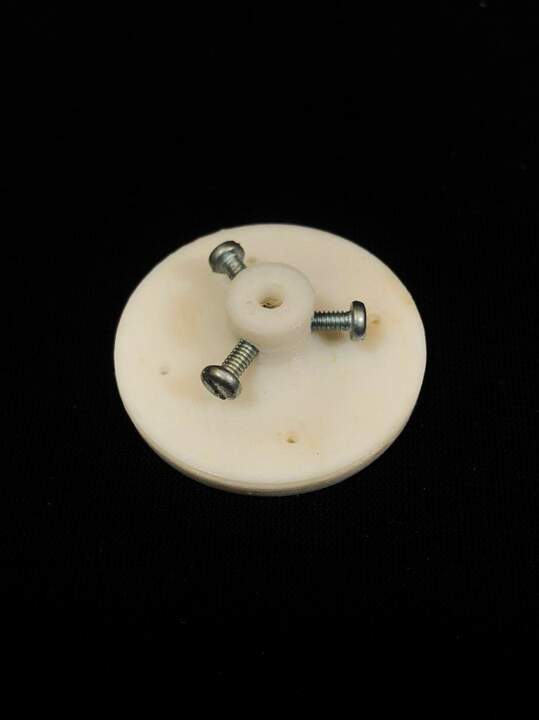
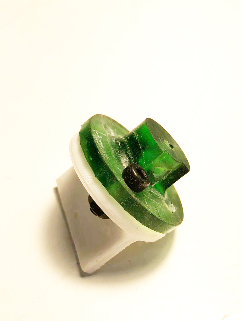
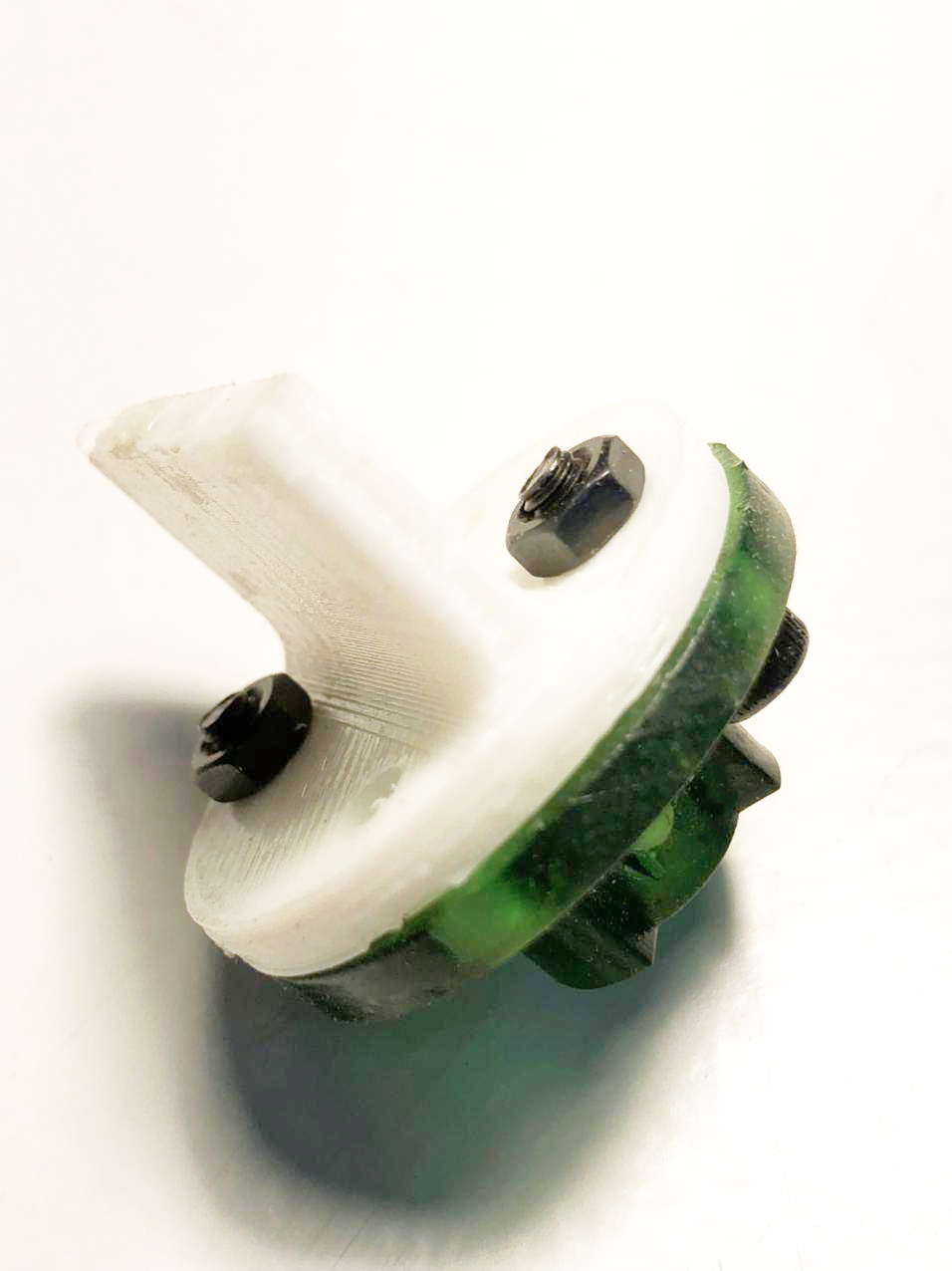
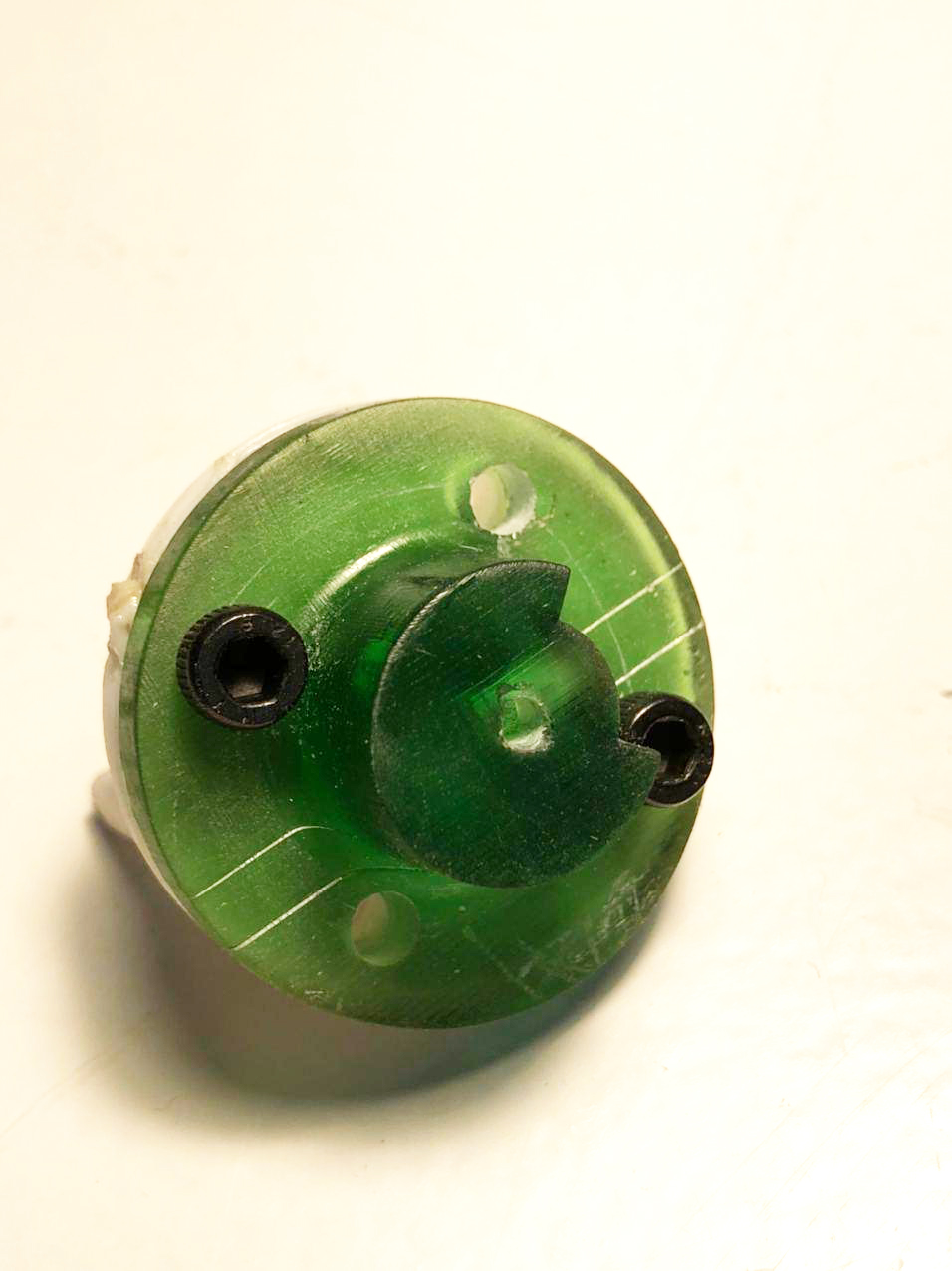
Extra axes update
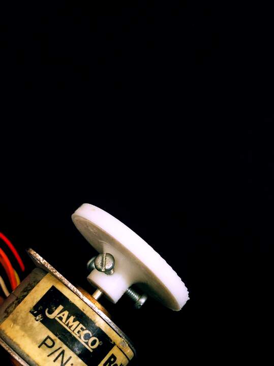
I had problem with shaft coupler so I used the SLA technique to print this particular part. Also I update the design with one screw from side. also made the holes a bit tighter.
SLA printing
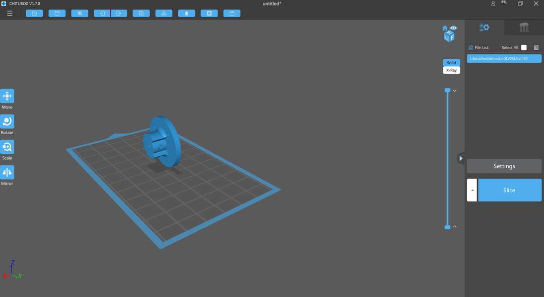
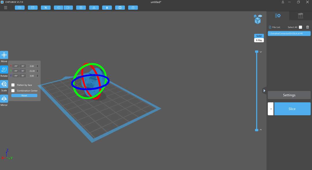
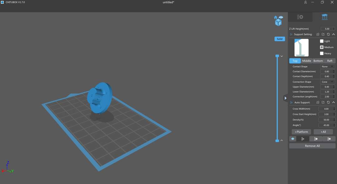
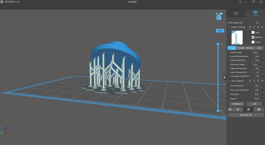
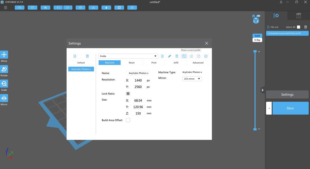
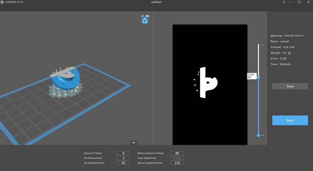
I have used Chitubox for slicing the geometry for the anyCubic Photon S. The process was very simple and fast for making the file ready. First I import the geometry. then I changed the orientation of its plane so I could add the supports. In the next step I used auto-generative support to add supports. But you can also edit them manually. Later on I set the setting of the slicer for the Photon s machine and base on the resin, select the specification for the light exposure. After slicing you can save the file in photon format and printed on the machine.
SLA Post process
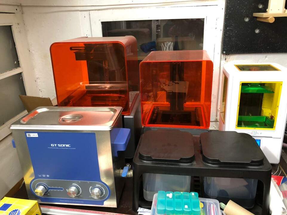
SLA Process is very easy at the beginning but it will get mess at the end! :)) Make sure during all these processes ware gloves and cover the surfaces that you make touch. So After 5hr the print finished. I removed the platform from its stand. after removing my piece form the platform I put it in a ultrasonic cleaner for about 20 min. After that I pas it through the alcohol baths. At the end I placed the piece in the UVB chamber to pas las process of curing of the resin.
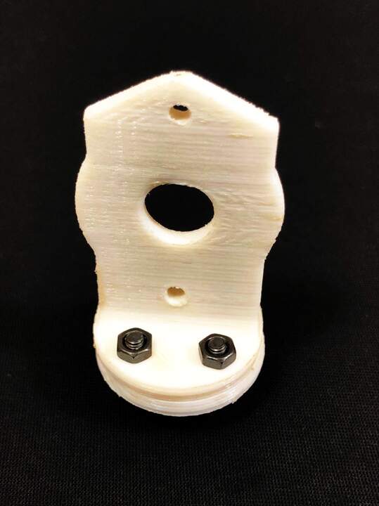
Final printed piece
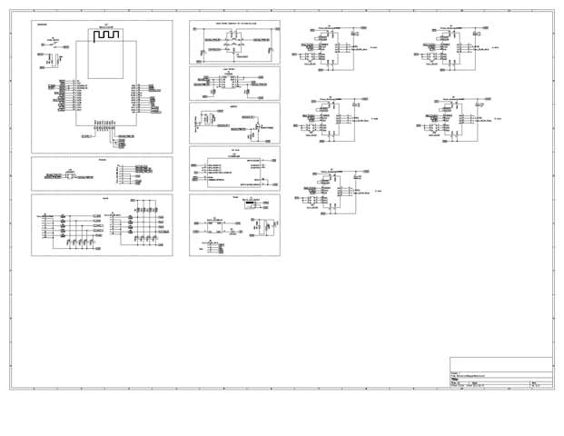
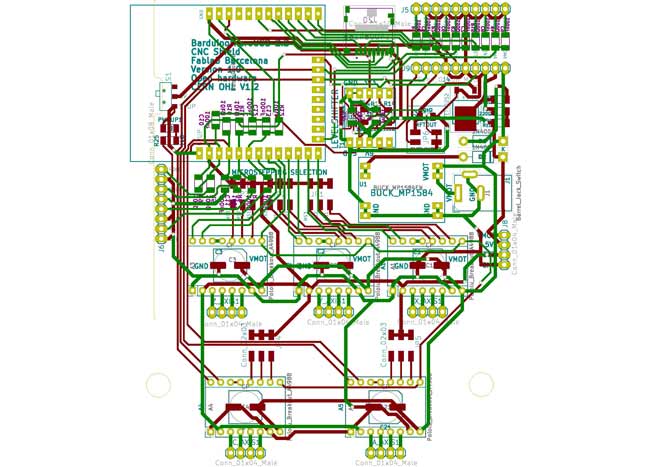
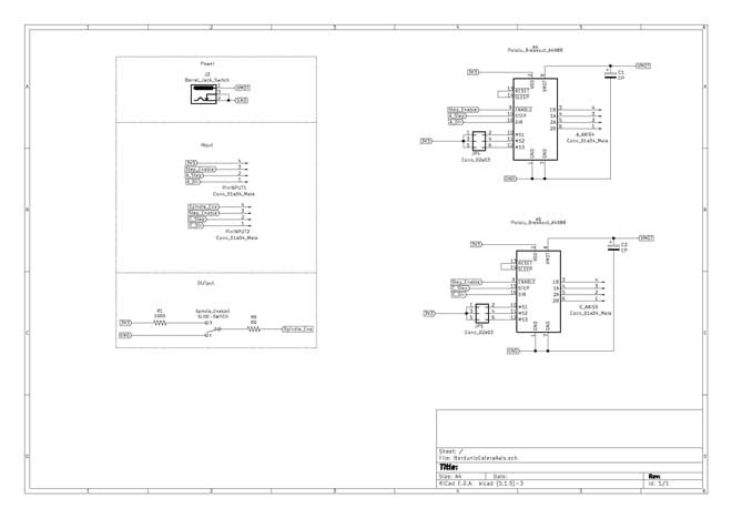
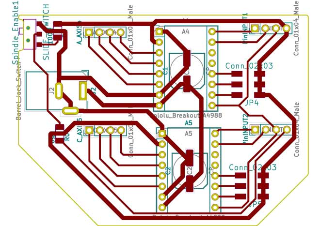
SPML5X Shield
I based my design on the main board that has developed for SPML. After going through the design of that board Which was a bit overwhelming. I start modifying the initial design to fit the extra drivers on the shield. After checking the available IO pins in ESP32 and compare it to the design that I already had, I realized that I need to remove couple of unnecessary pins in order to address the 2 extra drivers that I am adding. In total By adding this to extra axis I needed 2 pins for the driving the motors for each of them and 2 pins for checking the limitation sensors which sum up to 6 pins.
removed pins:
- Probe
- Flood
- Hold
- Door
- Mist
- Spindle_Ena
Added pins:
- A_Dir
- A_Step
- C_Step
- C_Dir
- A_limit _ C_limit
After consulting with the instructors they told me that they ordered the PCBs. So I needed to design and extension for the shield.
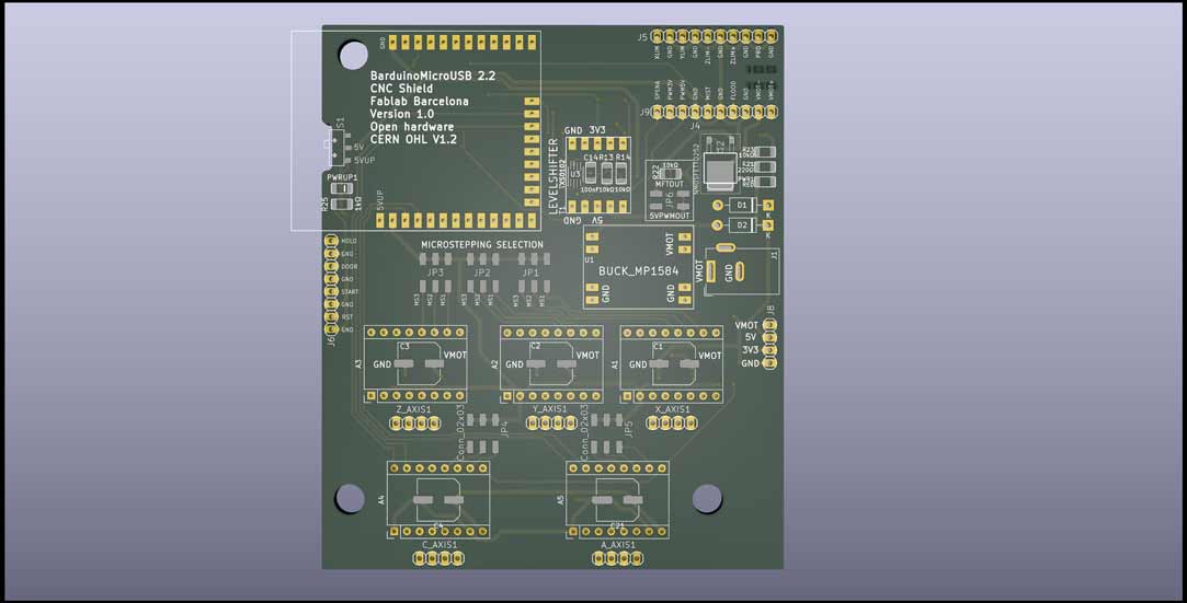
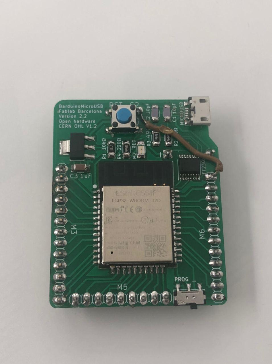
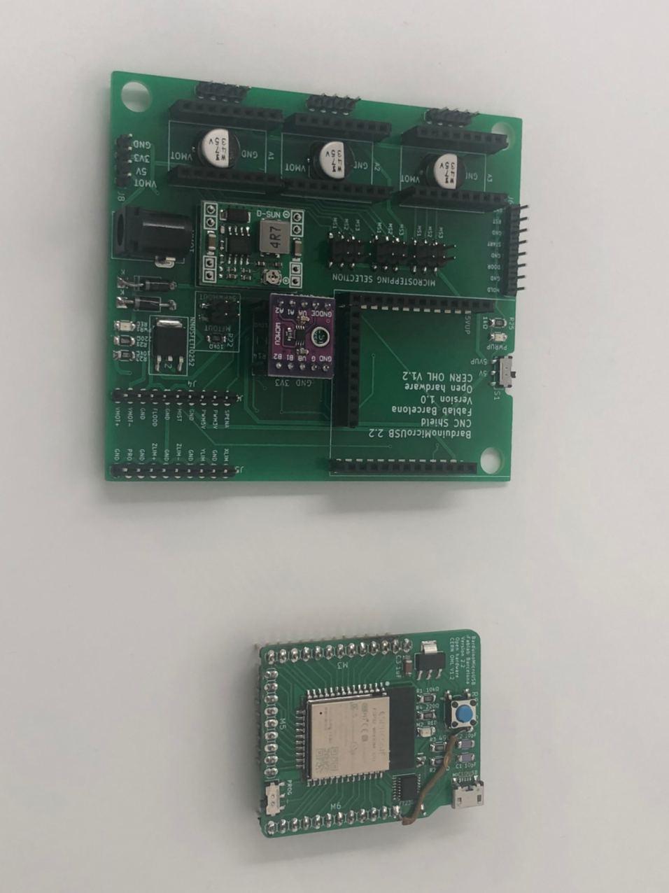
Barduino and SMPL shield
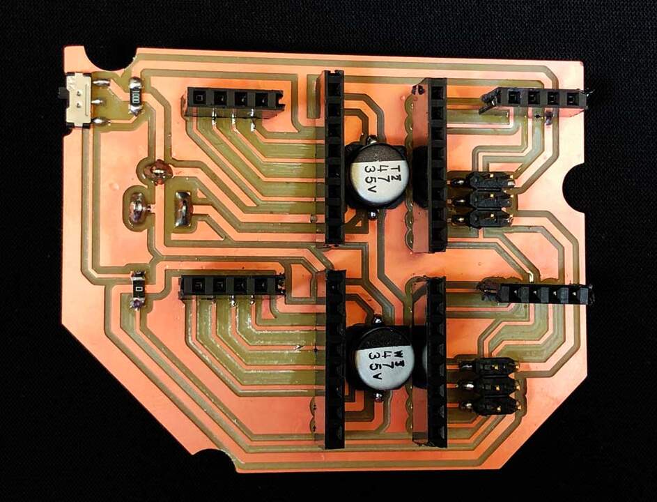
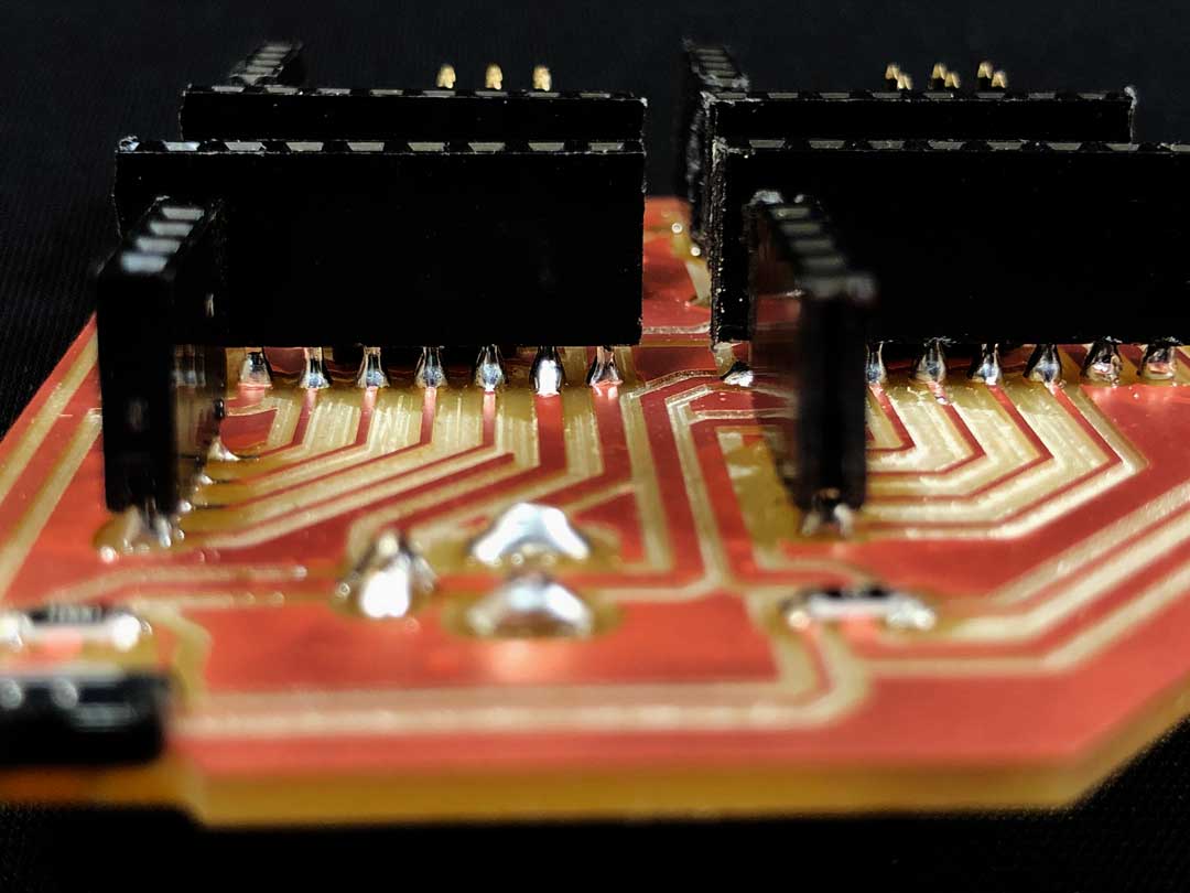
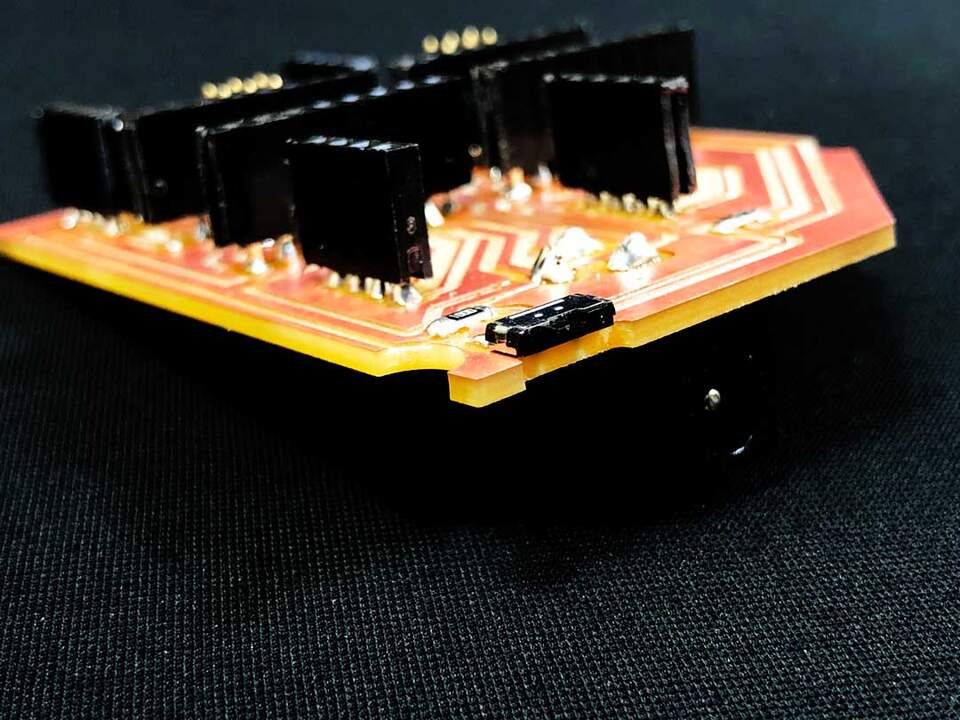
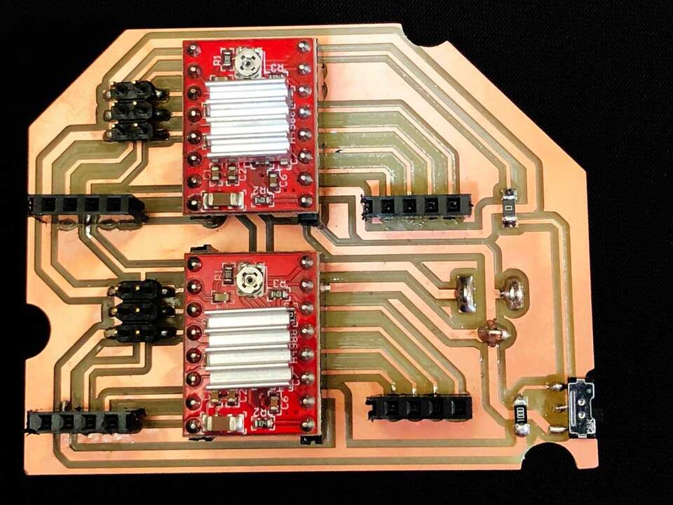
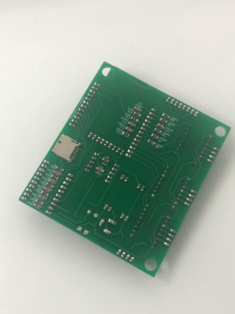
Also I needed to solder a Barduino2.0 and CNC shield that they have ordered. Was very long soldering session. After gathering all the components, I start the soldering from Barduino. As always ESP32 and Ft230xs was the hardest component to add. Mini USB also was quite challenging. After first check I found a small short between mini-usb legs. another challenging of soldering this board was making sure that the terminal legs are straight. On the shield, I start the soldering from the back since it has smaller components and it will not disturb the soldering on the other face. the other side was mostly terminals. you can check the final image of components
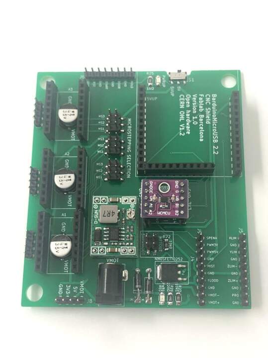

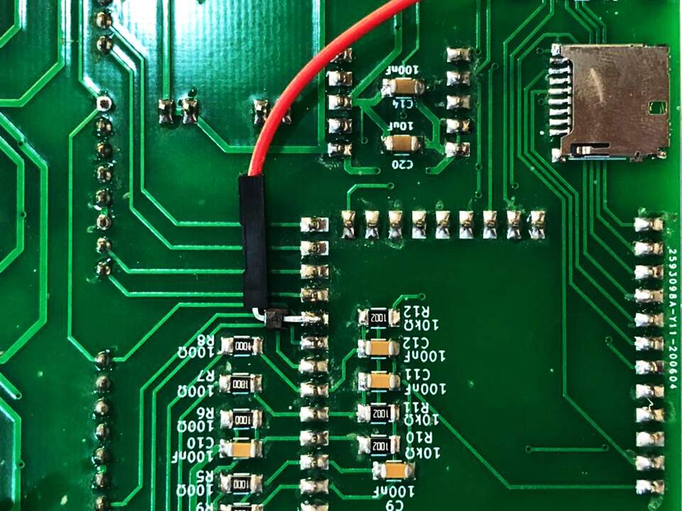
modification on CNC shield
During assemble I have realized that there is no out terminal for the step enable. well now there is! So I solder a wire directly to the board.
grbl Firmware
I start reading the codes grbl to get a better understanding for machines. It sound ridicules but it helped me a lot to realize the architecture of system. Now I know where should I modify and where I should not touch.
I am using grbl32 firmware which has been modified for the ESP32 processor.
In general grbl lib which developed for Arduino boards there is cpu_map.h
where you can modify the IO ports adjust it to your machine. However in the grbl32
there is a folder called machines where you can open a specific file for your machine and
define the pins and soft-limits.
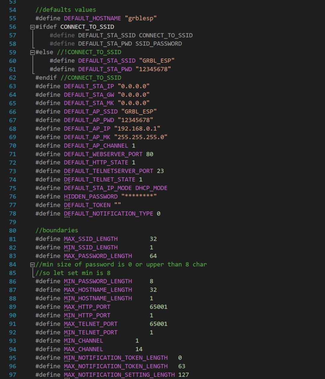
the other difference is the wifi configuration files which has been added in case of ESP32.
Also most of the file are pairs one file is the code and the other is a set of direction for compiling the code.
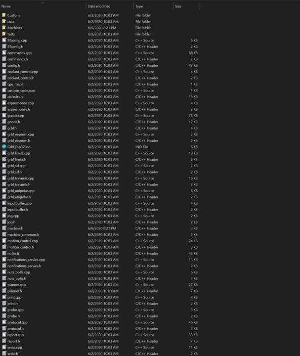
After these analysis I made a spml5x.h file in the machines directory and add the name of the machine to the machine.h file.
spml5x.h
#define MACHINE_NAME            "SixPackMachineLab5X"

#define X_STEP_PIN              GPIO_NUM_12
#define X_DIRECTION_PIN         GPIO_NUM_14
#define Y_STEP_PIN              GPIO_NUM_27
#define Y_DIRECTION_PIN         GPIO_NUM_26
#define Z_STEP_PIN              GPIO_NUM_33
#define Z_DIRECTION_PIN         GPIO_NUM_32
#define A_STEP_PIN              GPIO_NUM_8
#define A_DIRECTION_PIN         GPIO_NUM_15
#define C_STEP_PIN              GPIO_NUM_36
#define C_DIRECTION_PIN         GPIO_NUM_39

#define LIMIT_MASK              B111
#define X_LIMIT_PIN             GPIO_NUM_17
#define Y_LIMIT_PIN             GPIO_NUM_16
#define Z_LIMIT_PIN             GPIO_NUM_23
#define A_LIMIT_PIN             GPIO_NUM_22
#define C_LIMIT_PIN             GPIO_NUM_21

// OK to comment out to use pin for other features
#define STEPPERS_DISABLE_PIN    GPIO_NUM_25

#define SPINDLE_PWM_PIN         GPIO_NUM_2   // labeled SpinPWM
//#define SPINDLE_ENABLE_PIN      GPIO_NUM_22  // labeled SpinEnbl
//#define MIST_PIN                GPIO_NUM_21  // labeled Mist
//#define FLOOD_PIN               GPIO_NUM_8  // labeled Flood
//#define PROBE_PIN               GPIO_NUM_15  // labeled Probe

#define CONTROL_SAFETY_DOOR_PIN GPIO_NUM_39  // labeled Door,  needs external pullup
#define CONTROL_RESET_PIN       GPIO_NUM_35  // labeled Reset, needs external pullup
#define CONTROL_FEED_HOLD_PIN   GPIO_NUM_36  // labeled Hold,  needs external pullup
#define CONTROL_CYCLE_START_PIN GPIO_NUM_34  // labeled Start, needs external pullup


#define DEFAULT_SOFT_LIMIT_ENABLE 0 // false
#define DEFAULT_HARD_LIMIT_ENABLE 0  // false

// Softlimit

#define DEFAULT_X_MAX_TRAVEL 200.0 // mm NOTE: Must be a positive value.
#define DEFAULT_Y_MAX_TRAVEL 200.0 // mm NOTE: Must be a positive value.
#define DEFAULT_Z_MAX_TRAVEL 100.0 // mm NOTE: Must be a positive value.
#define DEFAULT_A_MAX_TRAVEL 100.0 // mm NOTE: Must be a positive value.
#define DEFAULT_C_MAX_TRAVEL 100.0 // mm NOTE: Must be a positive
here because of pin limitation I removed the accessories such as mist, flood, door, and spindle enable pin to assign them to the extra axis that has been added to spml.
ESP32-grbl Firmware Update
I recently check the ESP-GRBL repo and realized that hey published a new version with more support for up to 6 axes machines. Also there was a huge update on the file organization system. So I decided to update my firmware to the new version. As previous version the I needed to add my machine specific pin out to the machine file. The only update was that I need to define the number of the axes in here.
#define MACHINE_NAME            "spml5x"

#ifdef N_AXIS
#    undef N_AXIS
#endif
#define N_AXIS 4

#define X_STEP_PIN              GPIO_NUM_12
#define X_DIRECTION_PIN         GPIO_NUM_14
#define Y_STEP_PIN              GPIO_NUM_27
#define Y_DIRECTION_PIN         GPIO_NUM_26
#define Z_STEP_PIN              GPIO_NUM_33
#define Z_DIRECTION_PIN         GPIO_NUM_32
//#define A_STEP_PIN              GPIO_NUM_8
//#define A_DIRECTION_PIN         GPIO_NUM_21
#define C_STEP_PIN              GPIO_NUM_36
#define C_DIRECTION_PIN         GPIO_NUM_39

#define LIMIT_MASK              B111
#define X_LIMIT_PIN             GPIO_NUM_17
#define Y_LIMIT_PIN             GPIO_NUM_16
#define Z_LIMIT_PIN             GPIO_NUM_4
//#define A_LIMIT_PIN             GPIO_NUM_22
//#define C_LIMIT_PIN             GPIO_NUM_21

// OK to comment out to use pin for other features
#define STEPPERS_DISABLE_PIN    GPIO_NUM_25

#define SPINDLE_PWM_PIN         GPIO_NUM_2   // labeled SpinPWM
//#define SPINDLE_ENABLE_PIN      GPIO_NUM_22  // labeled SpinEnbl
//#define MIST_PIN                GPIO_NUM_21  // labeled Mist
//#define FLOOD_PIN               GPIO_NUM_8  // labeled Flood
//#define PROBE_PIN               GPIO_NUM_15  // labeled Probe

//#define CONTROL_SAFETY_DOOR_PIN GPIO_NUM_39  // labeled Door,  needs external pullup
#define CONTROL_RESET_PIN       GPIO_NUM_35  // labeled Reset, needs external pullup
//#define CONTROL_FEED_HOLD_PIN   GPIO_NUM_36  // labeled Hold,  needs external pullup
#define CONTROL_CYCLE_START_PIN GPIO_NUM_34  // labeled Start, needs external pullup


#define DEFAULT_SOFT_LIMIT_ENABLE 0 // false
#define DEFAULT_HARD_LIMIT_ENABLE 0  // false

// Softlimit

#define DEFAULT_X_MAX_TRAVEL 200.0 // mm NOTE: Must be a positive value.
#define DEFAULT_Y_MAX_TRAVEL 200.0 // mm NOTE: Must be a positive value.
#define DEFAULT_Z_MAX_TRAVEL 100.0 // mm NOTE: Must be a positive value.
#define DEFAULT_A_MAX_TRAVEL 100.0 // mm NOTE: Must be a positive value.
#define DEFAULT_C_MAX_TRAVEL 100.0 // mm NOTE: Must be a positive value.
As you can see in the code I had to comment out one of my axes. Apparently ESP32 has a problem to use GPIO_8 and GPIO_15. because when I had these two active the board was constantly resetting.
Video
you can find the video of working prototype here.
Conclusion and future works
It was an amazing experince to build the machien for sure there are so many aspect need to take in consideration. from mechanical point of view to electronic and programming all of this skills getting involve. For the future I think I would change the stepper for extra axes with servo motor since it is easier to operate. It does not need an extra board. Also it would be much more stronger then stepper motor in this scale.
files
All the design and fabrication file are available here.